Transcription
The surveying and data processing ofthe primary control network for CSNSDivision of Accelerator TechnologyDongguan Campus,IHEPWANG Tong2014.10.16
Contents1、Project Overview2、Introduce of the Primary Control Network3、Surveying for the Horizontal Control Network4、Data Procesing for the Horizontal Control Network5、Surveying and Data Procesing for the Vertical ControlNetwork6、 Conclusion
1、Project Overview
1.1 Brief introductionChina Spallation Neutron Source(CSNS) mainly consistsof an H- Linac and a proton rapid cycling synchrotron. It isdesigned to accelerate proton beam pulses to 1.6 GeV kineticenergy at 25 Hz repetition rate, striking a solid metal targetto produce spallation neutrons.
RCSLinacOfficeBuildingExperimentHallSpectrometer
1.2 General layout of CSNSThe length of the H- Linac isabout 197m, the circumferenceof the proton rapid cyclingsynchrotron(RCS) is about228m, the length of the Linac toRCS beam transport (LRBT) isabout 40m, and length of theRCS to target transport(RTBT)is about 144m.
1.3 The status of the civil constructionThe construction of CSNS is in progress.Up to now,We havefinished the surveying of ground control net.Since the tunnel ofLinac has already been able to meet the requirement ofsurveying, we have finished the fourth measurement of thesecondary control network in Linac. And the baseplate andequipment skirt of Target have also began installing.
2、Introduce of the primary network
2.1 Overall layout of primary networkThe control network of CSNS is classified into twogrades: the primary network and the secondary network.The primary network consists of 27 points, which aredistributed over the whole area of CSNS. It is used for thelayout of buildings and facility and to provide highaccuracy control for the secondary network .
The yellow points :permanent monumentsbased on bed rock in thetunnel, are also thecomponent of thesecondary controlnetwork.The blue points :densification monumentsbuilt on the surface ofground.
2.2 Survey scheme for the primary networkThe surveying were divided into horizontal and verticalmeasurement separately.For the high precision and flexibility, GPS was put into use inhorizontal observation. And we can get the horizontalcoordinates of the control points by projection on a referenceellipsoid of the earth.The height difference measurement was carried out by spiritleveling.
3、Surveying for the horizontal controlnetwork
3.1 The overview of horizontal surveying4 GPS receivers GS15 were applied and 15 points weremeasured in the horizontal control network.In each station,the GPS receivers are centered on every 4 monuments. FromJun. 29 to Jul.23 in 2013,20 time intervals were obtained,andeach time interval spent 8 hours.
3.2 The method of centering for the largeheight differenceThe control points P01-P08 were located in tunnel, theycan’t directly connect with the other points on the ground. Tocarry out the survey, we should project them from tunnel tothe roofs vertically. Wild NL nadir telescope was consideredfor centering and projection.The problem is that there was a large height differencebetween tunnel and roof . To verify the correctness of thecentering of NL nadir, AT401 and a tooling were used.
3.2 The method of centering for the largeheight differenceWe designed a holder that could attract a 0.875inch ballreflector ,and it could be assembled on the bottom of the Leicacarrier ,and was concentric with the carrier.This tooling could be used not only for centering ,but alsofor the height difference measurement from the tunnel to theroof.
3.2 The method of centering for the largeheight differenceFirst, centering by NL nadir on the roof ,and put the carrier designedon the tribrach; then stationed and centered AT401 on the control pointsin the tunnel. Aim the AT401 to the zenith for the advantage of verticalrotation range 145 , and we could get the center of carrier on the roof.From the results of AT401,it shows that the deviation of centering was1.5mm at the height of 26m on point P01,and 0.8mm at the height of 12mon P02, which demonstrated that centering by NL nadir was correct andfeasible.
4、Data processing for the horizontalcontrol network
4.1 Distance distortion analysis ofTransverse Mercator projectionLGO software was used for the GPS data post-processing,and a plane coordinate system was got based on a mapprojection such as Transverse Mercator, which was acylindrical projection with central meridian placed in aparticular region.Since the plane coordinate systems are developed directlyfrom geodetic values, the use of observations require thefurther reduction of the ellipsoid values to grid values. Thereduction from ground to the state plane is a simple twostage process. Reduction from ground to the ellipsoid andreduction from the ellipsoid to the plane grid.
4.1 Distance distortion of TransverseMercator projectionThe main type of distortion was distance in TM mapprojection. In order to minimize the distance distortion, weneed to choose the appropriate central meridian:The distance reduction of the ellipsoid values to grid2values was: SS ym2R2 HmRWhere:Hm—Mean geodetic elevation .ym —Mean transverse projecting coordinates of thestarting and ending points of geodesic line.R —Mean Radius of the Earth.
4.2 GPS data processing by LGOWith the formula in 4.1, we can get the distance of theoptimal central meridian from the center of the surveyingregion. For the GPS data processing of primary control netof CSNS, the projective central meridian was setting as113 41′50″ finally and the Xian’ 80 reference ellipsoid waschoosed for the map projection.The parameters were then entered to the coordinatemanagement system of Leica Geo Office.
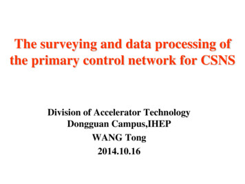
4.2 GPS data processing by LGOWe can get the horizontal coordinates of the primarycontrol network by LGO adjustment. The plane coordinatesof the control points are as follows:Contrl points randard deviation ofcoordinate/meast .75320.32529648.4780.52529721.8630.6Strandard deviation ofnorth .30.50.5
This figure showsthe absolute errorellipses and the map ofcontrol network.
4.3 Length comparison between GPSand Total stationWe also measurement several baselines by Total station tocheck the correctness of the results from LGO.The table belowshows that some deviations were large,but they are conform tothe nominal accuracy of GS15 (3mm 6TP03RP04RP05TP14TG12HP08SP02LP01LP07SDistance measurementby Total 899Distance from inverse calculationof horizontal .2-1.70.7-3.5-2.8-3.4
4.4 The stability of the control pointsin the primary control networkFrom Mar. 19 to Mar. 28,2014,we have conducted thesecond measurement of the primary control network,8 pointswere surveyed again.The best-fit comparision between the first and the second horizontal coordinatesPoints nameDeviation /m X/m 0.00020.0002G12H0.00090.00070.0012We can see that the deviation of P08S is a little large, adisplacement maybe occurred.
4.4 The stability of the control pointsin the primary control networkThe reason may be that the pillar of P08 is too long,about 22m withthe diameter of 1m,though it was built on the rock bed(P01,4m;P02,11m;P07,17m).The other reason is that Guangdong often rains hard,and the steelguard pipe will be full of water and monument was immerged after therain.Since the Target hall has not completed yet, P07 and P08 wereexposured in outdoor.
5、Surveying and data processing forvertical control network
4.1 Surveying for the vertical control networkNA 2 optical level was used for the height differencemeasurement,and every line of leveling we got the direct andreversed observing to ensure the high accuracy and to checkwith each other.And the distance between the level and the staffs would beabout the same distance in the backsight and the foresight ofevery station to eliminate the influence of i angle error.18 lines were measured.
4.2 Data processing for the vertical controlnetworkCOSA software was used for the adjustment of the verticalcontrol network,which is developed by school of geodesy andgeomatics,Wuhan university.No.12345678910111213Height adjustment L42.4267Mh(mm)Starting point0.30.510.50.520.470.390.410.50.390.30.510.48
6、Conclusion
6.1 Conclusion The GPS is convenient,and in the post-processing of thestatic observation,the distortion in the map projectionshould be considered. The accuracy of the horizontal coordinates and theelevation of the primary control net were about 2mm and0.5mm,which could meet the requirement. The point P08 was not stable enough, next we need tosubstitute another points for it.
The end, thanks!
The surveying were divided into horizontal and vertical measurement separately. For the high precision and flexibility, GPS was put into use in horizontal observation. And we can get the horizontal coordinates of the control points by projection on a reference ellipsoid of the earth. The height difference measurement was carried out by spirit