Transcription
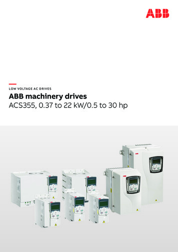
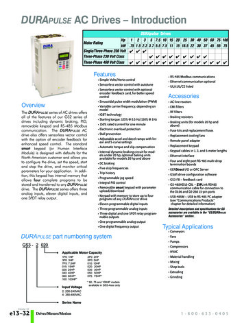
.DURApulse GS3 AC Drives – IntroductionGS3 AC DrivesHPkWMotor Rating230V Single-Phase Input / 230V Three-Phase Output230V Three-Phase Input / Output460V Three-Phase Input / OutputOverviewThe DURApulse series of AC drives offersall of the features of our GS2 series ofdrives including dynamic braking, PID,removable keypad and RS-485 Modbuscommunication. The DURApulse ACdrive also offers sensorless vector controlwith the option of encoder feedback forenhanced speed control. The standardsmart keypad (or Human Interface Module)is designed with defaults for the NorthAmerican customer and allows you toconfigure the drive, set the speed, startand stop the drive, and monitor criticalparameters for your application. Inaddition, this keypad has internal memorythat allows four complete programs to bestored and transferred to any DURApulsedrive. The DURApulse series offers threeanalog inputs, eleven digital inputs, andone SPDT relay output.10.7521.532.253.77.55.510 15 207.5 11 15444444444444444Features44 Simple Volts/Hertz control Sensorless vector control with autotune Sensorless vector control with optionalencoder feedback card, for better speedcontrol Sinusoidal pulse width modulation (PWM) Variable carrier frequency, depending onmodel IGBT technology Starting torque: 125% @ 0.5 Hz/150% @ 1Hz 150% rated current for one minute Electronic overload protection Stall prevention Adjustable accel and decel ramps withlinear and S-curve settings Automatic torque and slip compensation Internal dynamic braking circuit for modelsunder 20 hp; optional baking units availablefor models 20 hp and above DC braking Five skip frequencies Trip history Programmable jog speed Integral PID control Removable smart keypad with parameterupload/download Keypad with memory to store up to fourprograms of any DURApulse drive Eleven programmable digital inputs Three programmable analog inputs Three digital and one SPDT relayprogrammable outputs One programmable analog output One digital frequency output RS-485 Modbus communications Ethernet communication optional Two-year warranty UL/cUL/CE listed442518.54430 40 50 60 7522 30 37 45 5544444444100754Accessories AC line reactors EMI filters RF filter Braking resistors Braking units (for models 20 hp and above) Fuse kits and replacement fuses Replacement cooling fans Remote panel adapter Replacement keypad Keypad cables in 1, 3, and 5-meter lengths Ethernet interface Four and eight-port RS-485 multi-droptermination boards GSoft drive configuration software GS3-FB – feedback card GS-485HD15-CBL – ZIPLink RS485communication cable for connection tothe DL06 and D2-260 15-pin ports USB-485M – USB to RS-485 PC adapter(see “Communications Products”chapter for detailed information) Detailed descriptions and specifications for GSaccessories are available in the “GS/DURApulseAccessories” section.Typical Applications Conveyors Fans Pumps Compressors HVAC Material handling Mixing Shop tools Extruding GrindingAC DrivestGSX-57
.DURApulse GS3 AC Drives Specifications230V ClassModel Name: GS3-xxxPriceHPkWMax Motor OutputOutputRating* InputRatingRated Output Current (A)Max Output VoltageRated 11518.5172533496575Three-phase 200 to 240V (proportional to input voltage)0.1 to 400 HzThree-phase200/208/220/230/240 VAC, 50/60Hz263450Single/Three-phaseRated Voltage/FrequencyRated Input Current (A)Voltage/Frequency ToleranceWatt Loss @ 100% I (W)Weight (lb [kg])11.9 /5.715.3 /7.622 / [4.24]60Voltage: 10% Frequency: 5%30138066075013.313.314.326.5[6.031] [6.031] [6.487][12]* All 3-phase power sources must be symmetrical.Do not connect any DURApulse drives to grounded, center-tapped delta transformers (which are typically used for lighting 43077.2[35]460V Class – Three-PhaseModel Name: GS3-xxx41P042P043P045P047P54010Maximum HPMotorkWOutputRated OutputOutput Current (A)Rating put FrequencyRatingRated InputCurrent (A)Voltage/FrequencyToleranceWatt Loss @100% I (W)Weight (lb hree-phase 380 to 480V (proportional to input voltage)0.1 to 400 HzThree-phase,380/400/415/440/460/480VAC, 50/60Hz3.24.35.911.21419253239Voltage: 10% Frequency: 4]25034513.213.5[6.002] 16.8[53]116.8[53]* All 3-phase power sources must be symmetrical.Do not connect any DURApulse drives to grounded, center-tapped delta transformers (which are typically used for lighting circuits).AC DrivestGSX-58
.DURApulse GS3 AC Drives General SpecificationsGeneral SpecificationsControl SystemRated Output FrequencyOutput Frequency ResolutionOverload CapacityTorque CharacteristicsBraking TorqueDC BrakingAcceleration/Deceleration TimeVoltage/Frequency PatternStall Prevention LevelKeypadFrequencySettingExternal ternal putTerminalsDigital3 transistors1 relayDigital SquareWaveAnalogOperating FunctionsProtective or DevicesProgrammingStatus DisplayKey FunctionsEnclosure RatingAmbient TemperatureStorage TemperatureAmbient HumidityVibrationInstallation LocationControl CharacteristicsPulse Width Modulation, Carrier frequency adjustable from 1–15 kHz depending on the model.This system determines the control methods of the AC drive.00: V/Hz open loop control01: V/Hz closed loop control02: Sensorless Vector03: Sensorless Vector with external feedback0.1 to 400.0 Hz0.1 Hz150% of rated current for 1 minuteIncludes auto-torque boost, auto-slip compensation, starting torque 125% @ 0.5 Hz / 150% @ 1.0 Hz20% without braking resistor, 125% with optional braking resistor (braking circuit built-in only for units under 20 hp)Operation frequency 60–0 Hz, 0–100% rated current, Start time 0.0–5.0 seconds, Stop time 0.0–25.0 seconds0.1 to 600 seconds (linear or non-linear acceleration/deceleration), second acceleration/deceleration availableSettings available for Constant Torque - low & high starting torque, Variable Torque - low & high starting torque, anduser configured20 to 200% of rated currentOperation SpecificationsSetting by UP or DOWN buttonsPotentiometer - 3 to 5 kΩ, 0 to 10 VDC (input impedance 10 kΩ), -10 to 10 VDC, 4 to 20 mA (input impedance250Ω),0 to 20 mA; Multi-Speed Inputs 1 to 4, RS-232C/RS-485 communication interfaceSetting by RUN , STOP , JOG , FWD , REV buttonsForward/Stop, Reverse/Stop (run/stop, fwd/rev), 3-wire control, Serial Communication RS-232C & RS-485 (ModbusRTU)11 user-programmable: FWD/STOP, REV/STOP, RUN/STOP, REV/FWD, RUN momentary (N.O.), STOP momentary(N.C.), External Fault (N.O./N.C.), External Reset, Multi-Speed Bit (1-4), Manual Keyboard Control, Jog, ExternalBase Block (N.O./N.C.), Second Accel/Decel Time, Speed Hold, Increase Speed, Decrease Speed, Reset Speed toZero, PID Disable (N.O.), PID Disable (N.C.), Input Disable3 user-configurable, 0 to 10V (input impedance 10 kΩ), 0 to 20 mA, 4 to 20 mA (input impedance 250Ω), 10 bitresolution -10V to 10V, 10 bit resolution4 user-programmable: Inverter Running, Inverter Fault, At Speed, Zero Speed, Above Desired Frequency, BelowDesired Frequency, At Maximum Speed, Over Torque Detected, Above Desired Current, Below Desired Current, PIDDeviation Alarm, Heatsink Overheat Warning (OH), Soft Braking Signal, Above desired Frequency 2, Below desiredFrequency 2, Encoder LossOne digital square wave output representing drive frequency1 user-programmable, 0 to 10V, 8 bit resolution frequency, current, process variable PVAutomatic voltage regulation, voltage/frequency characteristics selection, non-linear acceleration/deceleration, upperand lower frequency limiters, 15-stage speed operation, adjustable carrier frequency (1 to 15 kHz), PID control, 5skip frequencies,analog gain & bias adjustment, jog, electronic thermal relay, automatic torque boost, trip history, software protectionElectronic Thermal, Overload Relay, Auto Restart after Fault, Momentary Power Loss, Reverse Operation Inhibit,Auto Voltage Regulation, Over-Voltage Stall Prevention, Auto Adjustable Accel/Decel, Over-Torque Detection Mode,Over-Torque Detection Level, Over-Torque Detection Time, Over-Current Stall Prevention during Acceleration, OverCurrent Stall Prevention during Operation9-key, 2 line x 16 character LCD display, 5 status LEDsParameter values for setup and review, fault codesOutput Frequency, Motor Speed, Scaled Frequency, Output Current, Motor Load, Output Voltage, DC Bus Voltage,PID Setpoint, PID Feedback, Frequency SetpointRUN, STOP/RESET, FWD/REV, PROGRAM, DISPLAY, UP , DOWN , ENTERProtected Chassis, IP20-10 C to 40 C (14 F to 104 F)-20 C to 60 C (-4 F to 140 F) – during short term transportation period20 to 90% RH (non-condensing)9.8 m/s2 (1G) less than 10 Hz; 5.9 m/s2 (0.6G) 10 to 60 HzAltitude 1000m or lower above sea level, keep from corrosive gas, liquid and dustNoise filter, input AC reactor, output AC reactor, cable for remote operator, programming software, dynamic brakingresistor, dynamic braking unit; RF filter; remote panel adapter; Ethernet interface; four and eight port RS-485 multidroptermination boards, replacement keypads, fuse kits and replacement fusesAC DrivestGSX-59
.DURApulse GS3 AC Drives Specifications –InstallationUnderstanding the installation requirementsfor your DURApulse AC drive will helpto ensure that it operates within itsenvironmental and electrical limits.Note: Never use only this catalog for installation instructions oroperation of equipment; refer to the user manual, GS3-M.Environmental SpecificationsAmbient Operating TemperatureHumidityTo 90% (no condensation)9.8 m/s2 (1g), less than 10 Hz5.9 m/s2 (0.6g),10 to 60 HzAltitude 1,000 m or less, indoors (no corrosivegases, liquids or dust)41: Protective structure is based upon EN605292: The ambient temperature must be in the range of-10 to 40 C. If the range will be up to 50 C, you will need to set the carrier frequency to 2.1 kHz orless and derate the output current to 80% or less.3: The storage temperature refers to the short-term temperature during transport.4: Conforms to the test method specified in JIS CO911 (1984)Watt-loss ChartAt full 10 to 40 C (14 F to 104 F)-20 to 60 C (-4 F to 140 F)LocationGS3-21P02Storage Temperature 3VibrationGS3 Drive ModelIP20Protective Structure 1150mm (6 inches)Air Flowor more50mm(2 inches)or more50mm(2 inches)or moreEnclosure150mm (6 inches)or moreMinimum Clearances and Air FlowWARNING: AC DRIVES GENERATE A LARGE AMOUNT OF HEAT WHICH MAY DAMAGETHE AC DRIVE. AUXILIARY COOLING METHODS ARE TYPICALLY REQUIRED IN ORDERNOT TO EXCEED MAXIMUM AMBIENT TEMPERATURES.WARNING: MAXIMUM AMBIENT TEMPERATURES MUST NOT EXCEED 50 C (122 F),OR 40 C (104 F) FOR MODELS 7.5 HP (5.5 KW) AND HIGHER!AC DrivestGSX-60
.DURApulse GS3 AC Drives Specifications —TerminalsMain Circuit TerminalsTerminalDescriptionL1, L2, L3Input PowerT1, T2, T3AC Drive OutputB1, B2Braking Resistor Connection (Under 20HP) 2, – (negative)External Dynamic Brake Unit (20HP & Over)GroundGS3-4030 shownControl Circuit TerminalsTerminal SymbolDescriptionRemarks 24VDI1DI2DI3DI4DI5DI6DI7DI8DI9DI10DI11DCM 10VAI1AI2AI3ACMDC Voltage SourceDigital Input 1Digital Input 2Digital Input 3Digital Input 4Digital Input 5Digital Input 6Digital Input 7Digital Input 8Digital Input 9Digital Input 10Digital Input 11Digital CommonInternal Power SupplyAnalog InputAnalog InputAnalog InputAnalog Common( 24V, 20mA), used only for AC drive digital inputs wired for source mode operationR1ORelay Output 1 Normally OpenR1CRelay Output 1 Normally ClosedR1Relay Output 1 CommonDO1DO2DO3DOCAOFOPhotocoupled digital outputPhotocoupled digital outputPhotocoupled digital outputDigital Output CommonAnalog OutputDigital Frequency OutputInput Voltage: Internally Supplied (see Warning below)Sink Mode: Low active, VinL Min 0V, VinL Max 15V,Iin Min 2.1mA, Iin Max 7.0mASource Mode: High active, VinH Min 8.5V, VinH Max 24V, Iin Min 2.1mA, Iin Max 7.0mAInput response: 12–15 msecAlso see “Basic Wiring Diagram” on the next pages. 10VDC (10mA maximum load)0 to 10 V input only0 to 20mA / 4 to 20mA input-10 to 10 V input onlyResistor Load:240VAC - 5A (N.O) / 3A (N.C.)24VDC - 5A (N.O.) / 3A (N.C.)Inductive Load:240VAC - 1.5A (N.O) / 0.5A (N.C)24VDC - 1.5A (N.O) / 0.5A (N.C) See P 3.01 to P 3.03Maximum 48VDC, 50mA0 to 10 V 2mA OutputSquare wave pulse train outputWarning: DO NOT CONNECT EXTERNAL VOLTAGE SOURCES TO THE DIGITAL INPUTS. PERMANENT DAMAGE MAY RESULT.Note: Use twisted-shielded, twisted-pair or shielded-lead wires for the control signal wiring. It is recommended torun all signal wiring in a separate steel conduit. The shield wire should only be connected at the AC drive. Donot connect shield wire on both ends.AC DrivestGSX-61
.DURApulse GS3 AC Drives – Basic WiringDiagramPower Wiring Diagram – drives under 20 hpNote: Users MUST connect wiring according to the circuit diagram shown below. (Refer to user manual GS3-M for additional specific wiring information.)Note: P lease refer to the following pages for explanations and information regarding feedback cards (pg.tGSX-108), line reactors (pg.tGSX-110), braking components (pg.tGSX-1), EMI filters(pg.tGSX-141), RF filters (pg.tGSX-150), and fuses (pg.tGSX-151).Braking resistor(optional)BRJUMPER Power Source200-240V -10%(50,60Hz -5%)380-480V -10%(50,60Hz -5%)Use any two of L1, L2, L3for 230V 1-phase modelsL1L2L3B1(–)B2DURAPULSEGS3-xxxxAC MotorT1IM3ØT2T3Note: Grounding terminalsare internally connected.Motor groundingterminalGrounding resistanceless than 0.1MechanicalCouplingAABBGS3-FB(optional)OC 12VFactoryDefaultOC open collectorTP totem poleMain circuit (power) terminalsVPDCMTP 5VControl circuit terminalABPG 12VGNDEncoderOutput 12VDCShielded leadsWarning: DO NOT PLUG A MODEM OR TELEPHONE INTO THE GS3/DURApulse RJ-12 SERIAL COMM PORT, OR PERMANENTDAMAGE MAY RESULT.TERMINALS 2 AND 5 SHOULD NOT BE USED AS A POWER SOURCE FOR YOUR COMMUNICATION CONNECTION.AC DrivestGSX-62
.DURApulse GS3 AC Drives – Basic WiringDiagramPower Wiring Diagram – 20 to 30 hp (230 VAC) & 20 to 60 hp (460 VAC)Note: Users MUST connect wiring according to the circuit diagram shown below. (Refer to user manual GS3-M for additional specific wiring information.)Note: P lease refer to the following pages for explanations and information regarding feedback cards (pg.tGSX-108), line reactors (pg.tGSX-110), braking components (pg.tGSX-1), EMI filters(pg.tGSX-141), RF filters (pg.tGSX-150), and fuses (pg.tGSX-151).JUMPERPower Source 3-phase200-240V -10%(50,60Hz -5%)380-480V -10%(50,60Hz -5%)BRDynamicBrake Unit(optional) L1L2L3Braking resistor(optional)– 2DURAPULSEGS3-xxxxAC MotorT1IM3ØT2T3Note: Grounding terminalsare internally connected.Motor groundingterminalGrounding resistanceless than 0.1MechanicalCouplingAABBGS3-FB(optional)OC 12VFactoryDefaultOC open collectorTP totem poleMain circuit (power) terminalsVPDCMTP 5VControl circuit terminalABPG 12VGNDEncoderOutput 12VDCShielded leadsWarning: DO NOT PLUG A MODEM OR TELEPHONE INTO THE GS3/DURApulse RJ-12 SERIAL COMM PORT, OR PERMANENTDAMAGE MAY RESULT.TERMINALS 2 AND 5 SHOULD NOT BE USED AS A POWER SOURCE FOR YOUR COMMUNICATION CONNECTION.AC DrivestGSX-63
.DURApulse GS3 AC Drives – Basic WiringDiagramPower Wiring Diagram - 40 to 50 hp (230 VAC) & 75 to 100 hp (460 VAC)Note: Users MUST connect wiring according to the circuit diagram shown below. (Refer to user manual GS3-UMP for additional specific wiring information.)Note: Please refer to the following catalog pages in the Drives section of our catalog for explanations and information regarding feedback cards (X), line reactors (X), braking units(X) and resistors (X), EMI (X) and RF (X) filters, and fuses (X).BRDynamicBrake Unit(optional)200-240V -10%(50,60Hz -5%)380-480V -10%(50,60Hz -5%)BRDynamicBrake Unit(optional)JUMPERPower Source 3-phaseBraking resistor(optional) L1L2L3Braking resistor(optional)– 2DURAPULSEGS3-xxxxAC MotorT1IM3ØT2T3Note: Grounding terminalsare internally connected.Motor groundingterminalGrounding resistanceless than 0.1MechanicalCouplingAABBGS3-FB(optional)OC 12VFactoryDefaultOC open collectorTP totem poleMain circuit (power) terminalsVPDCMTP 5VControl circuit terminalABPG 12VGNDEncoderOutput 12VDCShielded leadsWarning: D O NOT PLUG A MODEM OR TELEPHONE INTO THE GS3/DURApulse RJ-12 SERIAL COMM PORT, OR PERMANENTDAMAGE MAY RESULT.TERMINALS 2 AND 5 SHOULD NOT BE USED AS A POWER SOURCE FOR YOUR COMMUNICATION CONNECTION.AC DrivestGSX-64
.DURApulse GS3 AC Drives – Control WiringDiagram – DI Connection to Sinking OutputsControl Wiring Diagram - Digital Input Connections to Sinking Output DevicesNote: Users must connect wiring according to the circuit diagram shown below.DURAPULSEAC DriveGS3-xxxxMulti-function Digital Inputs:Multi-function Output Contact: 24V Power Source(20mA max.)Forward/StopDI1Reverse/StopExternal Fault (N.O.)Multi-Speed 1Multi-Speed 2Input Mode SettingDI2SinkDI3SourceDI4R1R1C120VAC/24VDC @5A230VAC @2.5AR1OAC Drive RunningSW1DO1SinkDI5Multi-Speed 3DI6Multi-speed 448VDC @50mA max.AC Drive FaultDO248VDC @50mA max.At SpeedDO348VDC @50mA max.Zero SpeedDI7JOGMulti-function Digital Outputs:DI8External ResetDI9Second Accel/Decel TimeDI10External Base Block (N.O.)DI11DCMDigital Signal Com.DOCDigital Output Com.FOSee PowerWiring Diag.Analog Inputs:††Potentiometer5k†††† Frequency command sourcecan be one of the three analoginputs, up/down keys on keypador via the RS-485 serial commport. See parameter settings.Digital Frequency Output:1:1, Duty 50%DCM 10V Power Source(20mA max.)Multi-function Analog Output:AI1(0 to 10V)AI2(0-20mA or 4-20mA)ACMAI3(-10 to 10V)Indicates OutputFrequency Hz. –0-10VDC @ 2mARJ-12 Serial Comm Port*Interface (See Warning)ACMAnalog Signal Common6See PowerWiring DiagramPotentiometer(3-5 k )AO1RS-4851: 15V2: GND3: SG4: SG 5: NC* Optional ZIPLink serial communication cables availablefor plug and play connectivityFactory default source of frequency command is via the keypad up/down keysto AutomationDirect PLCs.See the comm cable selectionMain circuit (power) terminalsControl circuit terminalShielded leadsmatrix (pg.tGSX-162).Warning: DO NOT PLUG A MODEM OR TELEPHONE INTO THE DURApulse RJ-12 SERIAL COMM PORT, OR PERMANENTDAMAGE MAY RESULT.Factory default settingAC DrivestGSX-65
.DURApulse GS3 AC Drives – Control Wiring Diagram – DI Connections to Sourcing OutputsControl Wiring Diagram - Digital Input Connections to Sourcing Output DevicesNote: Users MUST connect wiring according to the circuit diagram shown below.DURAPULSEAC DriveGS3-xxxxMulti-function Digital Inputs:Multi-function Output Contact: 24V Power Source(20mA max.)Forward/StopDI1Reverse/StopInput Mode SettingDI2External Fault (N.O.)SinkDI4Multi-Speed 2R1C120VAC/24VDC @5A230VAC @2.5AR1OAC Drive RunningDO148VDC @50mA max.AC Drive FaultDO248VDC @50mA max.At SpeedDO348VDC @50mA max.Zero SpeedSW1DI3Multi-Speed 1R1SourceSinkDI5Multi-Speed 3DI6Multi-speed 4DI7JOGMulti-function Digital Outputs:DI8External ResetDI9Second Accel/Decel TimeDI10External Base Block (N.O.)DI11DCMDigital Signal Com.DOCDigital Output Com.FOSee PowerWiring Diag.Analog Inputs:††Potentiometer5k†††† Frequency command sourcecan be one of the three analoginputs, up/down keys on keypador via the RS-485 serial commport. See parameter settings.Digital Frequency Output:1:1, Duty 50%DCM 10V Power Source(20mA max.)Multi-function Analog Output:AI1(0 to 10V)Potentiometer(3-5 k )AOAI2(0-20mA or 4-20mA)ACM0-10VDC @ 2mAAI3(-10 to 10V)ACMAnalog Signal Common61 –Indicates OutputFrequency Hz.RJ-12 Serial Comm Port*Interface (See Warning)See PowerWiring DiagramFactory default settingRS-4851: 15V2: GND3: SG4: SG 5: NC* Optional ZIPLink serial communication cables availablefor plug and play connectivityto AutomationDirect PLCs.See the comm cable selectionmatrix (pg.tGSX-162).Factory default source of frequency command is via the keypad up/down keysMain circuit (power) terminalsControl circuit terminalShielded leadsWARNING: DO NOT PLUG A MODEM OR TELEPHONE INTO THE DURAPULSE RJ-12 SERIAL COMM PORT, OR PERMANENTDAMAGE MAY RESULT.AC DrivestGSX-66
.DURApulse GS3 AC Drives – DimensionsGS3-21P0, GS3-22P0, GS3-41P0, GS3-42P0118.0 [4.65]160.0 [6.30]108.0 [4.25]Dia. 5.5[0.22]RUN STOP JOG FWD REVPROGRAMRUNSTOPRESETFWD/REV185.0 [7.28]JOG173.0 [6.81]ENTERDISPLAYWA RNINGDo not connect AC power to output terminals T1,T2 and T3.Risk of electrical shock. Wait 10 minutes after removing power beforeservicing.Dia. 22.0 (0.87)Dia. 28.0[1 .10](2X )]0.118.7 [0.34]5[R2.75.5[0.22]GS3-43P0118.0 [4.65]145.0 [5.71]108.0 [4.25]Dia. 5.5[0.22]RUN STOP JOG FWD REVPROGRAMRUNSTOPRESETFWD/REV185.0 [7.28]JOG173.0 [6.81]ENTERDISPLAYWA RNINGDo not connect AC power to output terminals T1,T2 and T3.Risk of electrical shock. Wait 10 minutes after removing power beforeservicing.Dia. 22.0(0.87)Dia. 28.0(1.10)(2X).11]75[ 08.7 [0.34]R2.5.5[0.22]unit: mm(in)AC DrivestGSX-67
.DURApulse GS3 AC Drives – DimensionsGS3-23P0, GS3-25P0, GS3-45P03].1R0[5.2R3150.0 [5.91]135.0 [5.32]160.2 [6.31]RUN STOP JOG FWD REVPROGRAM244.3 [9.63]260.0[10.24]ENTERDISPL AYJOGFWD/REVSTOPRESETRUNWA RNINGDo not connect AC power to output terminals T1,T2 and T3.X)(27]8[0.022DDia.28.0 [1.10](2X).6ia]260.5[11.3 [0.44]Dia.Risk of electrical shock. Wait 10 minutes after removing power beforeservicing.GS3-27P5, GS3-2010, GS3-2015, GS3-47P5, GS3-4010, GS3-4015200.0 [7.88]Dia. 7.0 (0.28)185.6 [7.31]183.2 [7.22]RUN STOP JOG FWD REVJOGRUNSTOPRESETFWD/REV323.0 [12.73]ENTERDISPLAY303.0 [11.94]PROGRAMWA RNINGDo not connect AC power to output terminals T1,T2 and T3.Risk of electrical shock. Wait 10 minutes after removing power beforeservicing.5R3Dia. 42.6(1.68)13.5 [0.53]]140.[RDia. 22.0(0.87)7.0 [0.28]unit: mm(in)AC DrivestGSX-68
.DURApulse GS3 AC Drives – DimensionsGS3-2020, GS3-2025, GS3-2030, GS3-4020, GS3-4025, GS3-4030250.0 [9.84]Dia. 10.0 [0.39]226.0 [8.90]205.4 [8.08]RUN STOP JOG FWD REVPROGRAMENTERSTOPRESETFWD/REV384.0 [15.12]JOGRUN403.8 [15.90]DISPLAYWA RNINGDo not connect AC power to output terminals T1,T2 and T3.Risk of electrical shock. Wait 10 minutes after removing power beforeservicing.Dia. 28.0 (1.1)13.0 [0.51]Dia. 42.0 (1.65)(2X)10.0 [0.39]GS3-2040, GS3-2050, GS3-4040, GS3-4050, GS3-4060Dia. 13.0 (0.51)370.0 [14.57]260.0 [10.24]335.0 [13.19]Dia. 18.0(0.71)RUN STOP JOGFWD REVPROGRAMENTERDISPLAYFWD/REV595.0 [23.43]560.0 [22.05]RUNSTOPRESET589.0 [23.19]JOG18.0 [0.71]WA RNING132.5 [5.22]Dia. 62.0(2.44)21.0[0.83]Dia. 22.0(0.87)R6.5[0.25]13.0[0.51]unit: mm(in)AC DrivestGSX-69
.DURApulse GS3 AC Drives – DimensionsGS3-4075, GS3-4100425.0 [16.73]10.51)264.0 [10.39]Dia.18.0(0.71)660.0 [25.98]a.Di631.0 [24.84]385.0 [15.16](3.018.0 [0.71]WARNING130.4 [5.13]Dia. 74.8(2.94)21.0[0.83]280.0 [11.02]Dia. 22.0(0.87)R6.5[0.25]13.0[0.51]unit: mm(in)AC DrivestGSX-70
.AC Drives Optional Accessories – OverviewDrive Accessories(not all accessories are applicable for every drive model)1From power supplyDisconnect switch A Power SupplyPlease follow the specific power supply requirements as detailed in the specific drivemanual.B FusesInput fuses protect the AC drive from excessive input current due to line surges, shortcircuits, and ground faults. They are recommended for all installations and may berequired for UL-listed installations.2C Contactor (Optional)3 o not use a contactor or disconnect switch for run/stop control of the AC drive andDmotor. This will reduce the operating life cycle of the AC drive. Cycling a power circuitswitching device while the AC drive is in run mode should be done only in emergencysituations.465L1L2D Input Line Reactor (Optional)L3See the Line Reactors section atInput line reactors protect the AC drive from transient overvoltage conditions, typicallycaused by utility capacitor switching. The input line reactor also reduces the harmonicsassociated with AC drives. Input line reactors are recommended for all installations.AC Drive7E EMI filter (Optional)See the EMI Filters section atT1T2for more information.T36for more information.Input EMI filters reduce electromagnetic interference or noise on the input side of theAC drive. They are required for CE compliance and recommended for installationsprone to or sensitive to electromagnetic interference.F RF filter (Optional)8RF filters reduce the radio frequency interference or noise on the input or output side ofthe inverter.MotorMotor groundingterminalG Braking Unit and/or Braking Resistor (Optional)Dynamic braking allows the AC drive to produce additional braking (stopping) torque.AC drives can typically produce between 15% & 20% braking torque without theaddition of any external components. The addition of optional braking may be requiredfor applications that require rapid deceleration or high inertia loads.H Output Load Reactor or Voltage Time (dV/dT)Filter (Optional)Output line reactors protect the motor insulation against AC drive short circuits andIGBT reflective wave damage, and also “smooth” the motor current waveform, allowingthe motor to run cooler. They are recommended for operating “noninverter-duty”motors and when the length of wiring between the AC drive and motor is less than100 feet.Voltage Time filters provide enhanced protection for motors with distances up to1,000 feet.Voltage Time filters provide even more protection against wave reflection and reducecommon mode noise. They are recommended when the length of wiring between theAC drive and motor is from 100 feet up to 1,000 feet.Seefor specific product offerings.AC DrivestGSX-107
.GS3 DURApulse Accessories – FeedbackCardFeedback Card for DURApulseAC DrivesPart NumberPriceDrive ModelGS3-xxxxGS3-FBThe GS3-FB feedback card is for use only with DURApulseAC drives.DescriptionThe GS3-FB card is used toadd another layer of precisioncontrol to the already precisecontrol algorithm utilized in theDURApulse drive series. Thisadded control is activated byselecting control modes V/Hzclosed loop control or sensorlessvector with external feedback.The feedback mechanism usespulses generated by an externalencoder or pulse generator. Unlikeother feedback types, the GS3FB accommodates the four mostcommon encoder signal types:output voltage, open collector, linedriver, and complimentary.PGFeedbackOutput VoltageOpen collectorVCCI Gain10.03SW1 and SW2 switches5V12VOC12VOC12VTP 5VTP 5VOC12VOC12VTP 5VTP 5VQOC12VOC12VQTP 5VTP 5VOC12VOC12VTP 5VTP 5VO/P0VO/P0VLine driverComplimentaryOutputFrequencyOutputFreq. Limit10.04P Gain10.02Types of EncodersVCCClosed Loop DiagramFrequencyCommandVCCO/P0VAC DrivestGSX-108
.GS3 DURApulse Accessories – FeedbackCardWiring DiagramsPower Source 3-phase200-240V -10%(50,60Hz -5%)380-480V -10%(50,60Hz -5%)AC MotorL1L2L3DURAPULSEGS3-xxxxT1IM3ØT2T3Motor groundingterminalNote: Grounding terminalsare internally connected.Grounding resistanceless than 0.1MechanicalCouplingOC 12VFactoryDefaultOC open collectorTP totem poleTerminalSymbolsVPDCMA, NOT AB, NOT BA/O, B/OCOMMain circuit (power) terminalsAAABBGS3-FBOpen Collector typeEncoderVP 12VGNDDCMEncoderOutput 12VDCTP 5VControl circuit terminalShielded leadsPower Source 3-phaseDescription200-240V -10%(50,60Hz -5%)Power source of GS3-FB(SW1 can be switched to 12V or 5V)Output Voltage:( 12VDC 5% 200mA) or ( 5VDC 2% 400mA)Power source (VP) and input signal(A, B) commonInput signal from Encoder. Input typeis selected by SW2; Maximum 500kp/secGS3-FB output signal for usewith RPM Meter. (Open Collector)Maximum DC24V 100mAGS3-FB output signal (A/O, B/O)common380-480V -10%(50,60Hz -5%)PulseGeneratorPGBAC MotorL1L2L3DURAPULSEGS3-xxxxT1IM3ØT2T3Motor groundingterminalNote: Grounding terminalsare internally connected.Grounding resistanceless than 0.1MechanicalCouplingAABBGS3-FBLine Driver typeEncoder with RPMMeterOC 12VEncoderOutput 5VDCAAPulseB PG GeneratorB 5VVPGNDDCMOC open collectorTP totem poleTP 5VA/OB/OCOMMain circuit (power) terminalsControl circuit terminalRPM meterShielded leadsPower Source 3-phase200-240V -10%(50,60Hz -5%)380-480V -10%(50,60Hz -5%)Control Terminals BlockDesignationsAC MotorL1L2L3DURAPULSEGS3-xxxxT1IM3ØT2T3Motor groundingterminalNote: Grounding terminalsare internally connected.Grounding resistanceless than 0.1Fj1Connect to GS3series control boardWiring TerminalsGS3-FBSW1 SW2Select the powersource and encoderoutput typeOC 12VTP 5VA/OB/OCOMVPDCMAABBMechanicalCouplingOutput Voltage orComplementary typeEncoderOC 12VAAABBGS3-FBVPBMain circuit (power) terminalsTP 5VControl circuit terminalPulseGenerator 12VGNDDCMOC open collectorTP totem polePGEncoderOutput 12VDCShielded leadsAC DrivestGSX-109
Wiring Solutions.Wiring Solutions using the ZIPLink Wiring SystemZIPLinks eliminate the normally tedious process of wiring betweendevices by utilizing prewired cables and DIN rail mount connectormodules. It’s as simple as plugging in a cable connector at eitherend or terminating wires at only one end. Prewired cables keepinstallation clean and efficient, using half the space at a fraction ofthe cost of standard termi
DURApulse GS3 AC Drives Specifications 230V Class Model Name: GS3-xxx 21P0 22P0 23P0 25P0 27P5 2010 2015 2020 2025 2030 2040 2050 Price 4.00 3.00 7.00 3.00 2.00 Output Rating Max Motor Output HP 1.0 2.0 3.0 5.0 7.5 10 15 20 25 30 40 50 kW 0.75 1.5 2.2 3.7 5.5 7.5 11 15 18.5 22 30 37 Rated Output Current (A) 5 7 11 17 25 33 49 65 75 90 120 145 Max Output Voltage Three-phase 200 to 240V .