Transcription
Prices as of April 16, 2014. Check Web site for most current prices.DURApulse AC Drives – IntroductionDURApulse DrivesMotor RatingHp1235 7.5 10 15 20 25 30 40 50 60 75 100kW.75 1.5 2.2 3.7 5.5 7.5 11 15 18.5 22 30 37 45 55 75Single/Three-Phase Input 230V 4 4 4Three-Phase 230VClass4 4 4 4 4 4 4 4 4Three-Phase 460V ClassFeaturesOverviewThe DURApulse series of AC drives offersall of the features of our GS2 series ofdrives including dynamic braking, PID,removable keypad and RS-485 Modbuscommunication. The DURApulse ACdrive also offers sensorless vector controlwith the option of encoder feedbackfor enhanced speed control. The standard smart keypad (or Human InterfaceModule) is designed with defaults for theNorth American customer and allows youto configure the drive, set the speed, startand stop the drive, and monitor criticalparameters for your application. In addition, this keypad has internal memorythat allows four complete programs to bestored and transferred to any DURApulsedrive. The DURApulse series offers threeanalog inputs, eleven digital inputs, andone SPDT relay output. Simple Volts/Hertz control Sensorless vector control with autotune Sensorless vector control with optionalencoder feedback card, for better speedcontrol Sinusoidal pulse width modulation (PWM) Variable carrier frequency, depending onmodel IGBT technology Starting torque: 125% @ 0.5 Hz/150% @ 1Hz 150% rated current for one minute Electronic overload protection Stall prevention Adjustable accel and decel ramps withlinear and S-curve settings Automatic torque and slip compensation Internal dynamic braking circuit for models under 20 hp; optional baking unitsavailable for models 20 hp and above DC braking Five skip frequencies Trip history Programmable jog speed Integral PID control Removable smart keypad with parameterupload/download Keypad with memory to store up to fourprograms of any DURApulse drive Eleven programmable digital inputs Three programmable analog inputs Three digital and one SPDT relayprogrammable outputs One programmable analog outputDURApulse part numbering systemGS3 - 2 020Applicable Motor Capacity1P0: 1HP3P0: 3HP7P5: 7.5HP015: 15HP025: 25HP040: 40HP060: 60HP*100: 100HP*Input Voltage4 4 4 4 4 4 4 4 4 4 4 4 4 4 42P0: 2HP5P0: 5HP010: 10HP020: 20HP030: 30HP050: 50HP075: 75HP** 60, 75 and 100HP modelsavailable in GS3-4xxx only One digital frequency output RS-485 Modbus communications Ethernet communication optional Two-year warranty UL/cUL/CE listedAccessories AC line reactors EMI filters RF filter Braking resistors Braking units (for models 20 hp and above) Fuse kits and replacement fuses Replacement cooling fans Remote panel adapter Replacement keypad Keypad cables in 1, 3, and 5-meter lengths Ethernet interface Four and eight-port RS-485 multi-droptermination boards KEPDirect I/O or OPC Server GSoft drive configuration software GS3-FB – feedback card GS-485HD15-CBL – ZIPLink RS485communication cable for connection tothe DL06 and D2-260 15-pin ports USB-485M – USB to RS-485 PC adapter(see “Communications Products”chapter for detailed information)Detailed descriptions and specifications for GSaccessories are available in the “GS/DURApulseAccessories” section.Typical Applications Conveyors Fans Pumps Compressors HVAC Material handling Mixing Shop tools Extruding Grinding2: 200-240VAC4: 380-480VACSeries NameBook 2 (14.1)eDR-32AC Drives1-800-633-0405
Prices as of April 16, 2014. Check Web site for most current prices.DURApulse AC Drives SpecificationsCompanyInformationDrives230V ClassModel Name: GS3-xxxPrice21P022P023P025P0Soft Starters27P52010201520202025203020402050 242.00 293.00 347.00 400.00 549.00 698.00 889.00 1,104.00 1,298.00 1,486.00 2,177.00 2,637.00Maximum Motor OutputOutput Rated Output Current (A)RatingMaximum Output 9657590120145Three-phase 200 to 240V (proportional to input voltage)Rated Frequency* Input Rated Voltage/FrequencyRatingRated Input Current (A)Sensors:ProximityThree-phase200/208/220/230/240 VAC, 50/60Hz11.9 / 5.7 15.3 / 7.6 22 / 15.520.626Voltage/Frequency Tolerance3450607590110142Voltage: 10% Frequency: 5%Watt Loss @ 100% I (W)Weight (lb 35]Model Name: GS3-xxx41P0 42P0 43P0 45P0 47P5 4010 4015Price 323.00 360.00 385.00 427.00 613.00 734.00 957.00 1,165.00 1,383.00 1,570.00 2,001.00 2,436.00 2,788.00 3,130.00 3,498.00Watt Loss @ 100% I (W)Weight (lb 960639013016070102132176250345Sensors:Flow SwitchesProcessRelays andTimersVoltage: 10% Frequency: 5%3.94.44.19.413.213.5[1.759] [1.994] [1.857] [4.24] [6.002] 00/415/440/460/480VAC, 50/60Hz5.9Sensors:TemperatureStacklights0.1 to 400 Hz4.3Sensors:Limit SwitchesPushbuttonsand LightsThree-phase 380 to 480V (proportional to input voltage)3.2Sensors:EncodersSensors:Pressure460V Class – Three-PhaseMaximum Motor HPOutputkWOutput Rated Output CurrentRating (A)Maximum OutputVoltageRated FrequencyRated Voltage/*Input FrequencyRating Rated Input Current(A)Voltage/Frequency ToleranceSensors:PhotoelectricSensors:Current*A ll 3-phase power sources must be symmetrical.Do not connect any DURApulse drives to grounded, center-tapped delta transformers (which are typically used for lighting circuits).4020Motion: Servosand SteppersMotor Controls0.1 to 400 5]77.2[35]77.2[35]116.8[53]116.8[53]*A ll 3-phase power sources must be symmetrical.Do not connect any DURApulse drives to grounded, center-tapped delta transformers (which are typically used for lighting circuits).Pneumatics:Air PrepPneumatics:Directional Pneumatics:Air FittingsAppendixBook 2Terms andConditionsBook 2 (14.1)www.automationdirect.com/drivesAC DriveseDR-33
Prices as of April 16, 2014. Check Web site for most current prices.DURApulse AC Drives General SpecificationsGeneral SpecificationsControl CharacteristicsControl SystemPulse Width Modulation, Carrier frequency adjustable from 1k–15kHz depending on the model.This system determines the control methods of the AC drive.00: V/Hz open loop control01: V/Hz closed loop control02: Sensorless Vector03: Sensorless Vector with external feedbackRated Output Frequency0.1 to 400.0 HzOutput Frequency Resolution0.1 HzOverload Capacity150% of rated current for 1 minuteTorque CharacteristicsIncludes auto-torque boost, auto-slip compensation, starting torque 125% @ 0.5 Hz / 150% @ 1.0 HzBraking Torque20% without braking resistor, 125% with optional braking resistor (braking circuit built-in only for units under 20 hp)DC BrakingOperation frequency 60–0 Hz, 0–100% rated current, Start time 0.0–5.0 seconds, Stop time 0.0–25.0 secondsAcceleration/Deceleration Time0.1 to 600 seconds (linear or non-linear acceleration/deceleration), second acceleration/deceleration availableVoltage/Frequency PatternSettings available for Constant Torque - low & high starting torque, Variable Torque - low & high starting torque, and userconfiguredStall Prevention Level20 to 200% of rated currentOperation SignalDigitalSink/SourceSelectableAnalogSetting by UP or DOWN buttonsPotentiometer - 3 to 5 kq, 0 to 10 VDC (input impedance 10 kq), -10 to 10 VDC, 4 to 20 mA (input impedance 250q),0 to 20 mA; Multi-Speed Inputs 1 to 4, RS-232C/RS-485 communication interfaceSetting by RUN , STOP , JOG , FWD , REV buttonsForward/Stop, Reverse/Stop (run/stop, fwd/rev), 3-wire control, Serial Communication RS-232C & RS-485 (Modbus RTU)11 user-programmable: FWD/STOP, REV/STOP, RUN/STOP, REV/FWD, RUN momentary (N.O.), STOP momentary (N.C.),External Fault (N.O./N.C.), External Reset, Multi-Speed Bit (1-4), Manual Keyboard Control, Jog, External Base Block (N.O./N.C.), Second Accel/Decel Time, Speed Hold, Increase Speed, Decrease Speed, Reset Speed to Zero, PID Disable (N.O.), PIDDisable (N.C.), Input Disable3 user-configurable, 0 to 10V (input impedance 10 kq),0 to 20 mA, 4 to 20 mA (input impedance 250q), 10 bit resolution-10V to 10V, 10 bit resolutionDigital4 user-programmable: Inverter Running, Inverter Fault, At Speed, Zero Speed, Above Desired Frequency, Below Desired3 transistors Frequency, At Maximum Speed, Over Torque Detected, Above Desired Current, Below Desired Current, PID Deviation Alarm,Heatsink Overheat Warning (OH), Soft Braking Signal, Above desired Frequency 2, Below desired Frequency 2, Encoder Loss1 relayOutputTerminals Digital Square One digital square wave output representing drive frequencyWave1 user-programmable, 0 to 10V, 8 bit resolution frequency, current, process variable PVAnalogOutputsOperating FunctionsAutomatic voltage regulation, voltage/frequency characteristics selection, non-linear acceleration/deceleration, upper and lowerfrequency limiters, 15-stage speed operation, adjustable carrier frequency (1 to 15 kHz), PID control, 5 skip frequencies,analog gain & bias adjustment, jog, electronic thermal relay, automatic torque boost, trip history, software protectionProtective FunctionsElectronic Thermal, Overload Relay, Auto Restart after Fault, Momentary Power Loss, Reverse Operation Inhibit, Auto VoltageRegulation, Over-Voltage Stall Prevention, Auto Adjustable Accel/Decel, Over-Torque Detection Mode, Over-Torque DetectionLevel, Over-Torque Detection Time, Over-Current Stall Prevention during Acceleration, Over-Current Stall Prevention duringOperationOperator InterfaceEnvironmentOperator Devices9-key, 2 line x 16 character LCD display, 5 status LEDsProgrammingParameter values for setup and review, fault codesStatus DisplayOutput Frequency, Motor Speed, Scaled Frequency, Output Current, Motor Load, Output Voltage, DC Bus Voltage, PIDSetpoint, PID Feedback, Frequency SetpointKey FunctionsRUN, STOP/RESET, FWD/REV, PROGRAM, DISPLAY, UP , DOWN , ENTEREnclosure RatingProtected Chassis, IP20Ambient Temperature-10 C to 40 C (14 F to 104 F)Storage Temperature-20 C to 60 C (-4 F to 140 F) – during short term transportation periodAmbient Humidity20 to 90% RH (non-condensing)Vibration9.8 m/s2 (1G) less than 10 Hz; 5.9 m/s2 (0.6G) 10 to 60 HzInstallation LocationAltitude 1000m or lower above sea level, keep from corrosive gas, liquid and dustNoise filter, input AC reactor, output AC reactor, cable for remote operator, programming software, dynamic brakingresistor, dynamic braking unit; RF filter; remote panel adapter; Ethernet interface; four and eight port RS-485 multi-droptermination boards, replacement keypads, fuse kits and replacement fusesOptionsBook 2 (14.1)eDR-34AC Drives1-800-633-0405
Prices as of April 16, 2014. Check Web site for most current prices.DURApulse Drives Specifications – InstallationUnderstanding the installation requirements foryour DURApulse AC drive will help to ensurethat it operates within its environmental andelectrical limits.Note: Never use only this catalog for installation instructionsor operation of equipment; refer to the user manual, GS3-M.DrivesSoft StartersEnvironmental SpecificationsProtective Structure 1MotorsIP20PowerTransmissionAmbient Operating Temperature 2 -10 to 40 C (14 F to 104 F) fStorage Temperature 3-20 to 60 C (-4 F to 140 F)HumidityTo 90% (no condensation)Vibration 49.8 m/s2 (1g), less than 10 Hz5.9 m/s2 (0.6g),10 to 60 HzMotor ControlsLocationAltitude 1,000 m or less, indoors (no corrosivegases, liquids or dust)Sensors:ProximityMotion: Servosand Steppers1: Protective structure is based upon EN605292: The ambient temperature must be in the range of-10 to 40 C. If the range will be up to 50 C, you will need to set the carrier frequency to 2.1 kHz or less and derate the output current to 80% or less.3: The storage temperature refers to the short-term temperature during transport.Watt-loss ChartGS3 Drive ModelAt full emperature301380150mm (6 inches)660Sensors:LevelAir Flowor more750Sensors:Flow Switches9201430Pushbuttonsand Lights50mm(2 inches)or more50mm(2 inches)or ss176Relays andTimers150mm (6 inches)250or more345Pneumatics:Air Prep445620Pneumatics:Directional s:Limit Switches4: Conforms to the test method specified in JIS CO911 sMinimum Clearances and Air FlowWarning: AC drives generate a large amount of heat which may damage the AC drive.Auxiliary cooling methods are typically required in order not to exceed maximum s:Air FittingsAppendixBook 2Warning: M aximum ambient temperatures must not exceed 50 C (122 F), or 40 C (104 F)for models 7.5 hp (5.5 kW) and higher!Book 2 (14.1)www.automationdirect.com/drivesAC DriveseDR-35Terms andConditions
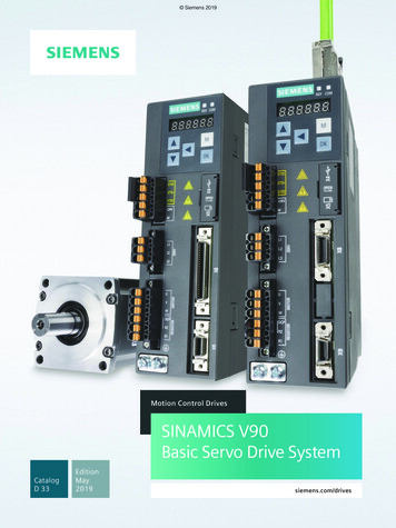
Prices as of April 16, 2014. Check Web site for most current prices.DURApulse AC Drives Specifications — TerminalsMain Circuit TerminalsTerminalL1, L2, L3T1, T2, T3B1, B2 2, – (negative)DescriptionInput PowerAC Drive OutputBraking Resistor Connection (Under 20HP)External Dynamic Brake Unit (20HP & Over)GroundGS3-4030 shownControl Circuit TerminalsTerminal Symbol 24VDI1DI2DI3DI4DI5DI6DI7DI8DI9DI10DI11DCM 10VAI1AI2AI3ACMDescriptionRemarksDC Voltage Source( 24V, 20mA), used only for AC drive digital inputs wired for source mode operationDigital Input 1Digital Input 2Digital Input 3Digital Input 4Digital Input 5Digital Input 6Digital Input 7Digital Input 8Digital Input 9Input Voltage: Internally Supplied (see Warning below)Sink Mode: Low active, VinL Min 0V, VinL Max 15V,Iin Min 2.1mA, Iin Max 7.0mASource Mode: High active, VinH Min 8.5V, VinH Max 24V, Iin Min 2.1mA, Iin Max 7.0mAInput response: 12–15 msecAlso see “Basic Wiring Diagram” on the next pages.Digital Input 10Digital Input 11Digital CommonInternal Power Supply 10VDC (10mA maximum load)Analog Input0 to 10 V input onlyAnalog Input0 to 20mA / 4 to 20mA inputAnalog Input-10 to 10 V input onlyAnalog CommonR1ORelay Output 1 Normally OpenR1CRelay Output 1 Normally ClosedR1Relay Output 1 CommonDO1DO2DO3DOCAOFOPhotocoupled digital outputPhotocoupled digital outputPhotocoupled digital outputResistor Load:240VAC - 5A (N.O) / 3A (N.C.)24VDC - 5A (N.O.) / 3A (N.C.)Inductive Load:240VAC - 1.5A (N.O) / 0.5A (N.C)24VDC - 1.5A (N.O) / 0.5A (N.C) See P 3.01 to P 3.03Maximum 48VDC, 50mADigital Output CommonAnalog Output0 to 10 V 2mA OutputDigital Frequency OutputSquare wave pulse train outputWarning: Do NOT connect external voltage sources to the digital inputs. Permanent damage may result.Note: Use twisted-shielded, twisted-pair or shielded-lead wires for the control signal wiring. It is recommended torun all signal wiring in a separate steel conduit. The shield wire should only be connected at the AC drive. Donot connect shield wire on both ends.Book 2 (14.1)eDR-36AC Drives1-800-633-0405
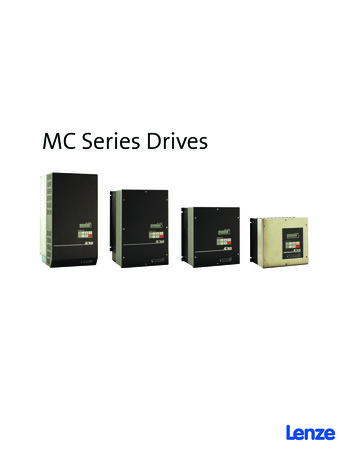
Prices as of April 16, 2014. Check Web site for most current prices.DURApulse AC Drives – Basic Wiring DiagramCompanyInformationDrivesPower Wiring Diagram - drives under 20 hpSoft StartersNote: Users MUST connect wiring according to the circuit diagram shown below. (Refer to user manual GS3-M for additional specific wiring information.)MotorsNote: Refer to the following pages for explanations and information regarding feedback cards, line reactors, braking resistors, EMI and RF filters, and fuses:DR-48, DR-50, DR-69, DR-74, DR-80, DR-81.PowerTransmissionMotion: Servosand SteppersBraking resistor(optional) Power Source200-240V -10%(50,60Hz -5%)380-480V -10%(50,60Hz -5%)Motor PULSEGS3-xxxxL3AC sSensors:Limit SwitchesT3Use any two of L1, L2, L3for 230V 1-phase modelsSensors:CurrentNote: Grounding terminalsare internally connected.Motor groundingterminalGrounding resistanceless than ratureSensors:LevelAABBGS3-FB(optional)OC 12VFactoryDefaultOC open collectorTP totem poleMain circuit (power) terminalsSensors:Flow SwitchesABPushbuttonsand LightsPGSignalDevices 12VProcessVPGNDDCMTP 5VControl circuit terminalStacklightsEncoderOutput 12VDCShielded leadsRelays andTimersPneumatics:Air PrepPneumatics:Directional ControlValvesPneumatics:CylindersWarning: D o not plug a modem or telephone into the GS3/DURApulse RJ-12 Serial Comm Port, or permanent damage may result.Terminals 2 and 5 should not be used as a power source for your communication connection.Pneumatics:TubingPneumatics:Air FittingsAppendixBook 2Terms andConditionsBook 2 (14.1)www.automationdirect.com/drivesAC DriveseDR-37
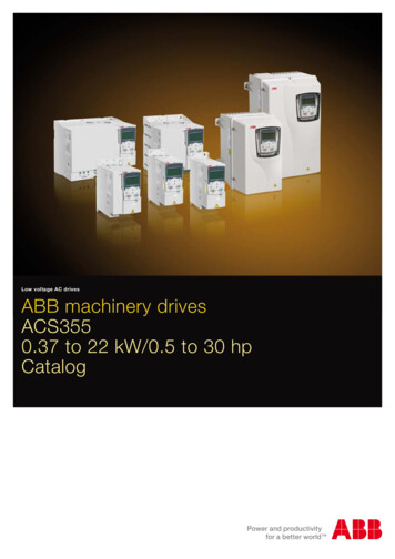
Prices as of April 16, 2014. Check Web site for most current prices.DURApulse AC Drives – Basic Wiring DiagramPower Wiring Diagram – 20 to 30 hp (230 VAC) & 20 to 60 hp (460 VAC)Note: Users MUST connect wiring according to the circuit diagram shown below. (Refer to user manual GS3-M for additional specific wiring information.)Note: Refer to the following pages for explanations and information regarding feedback cards, line reactors, braking units and resistors, EMI and RF filters, and fuses:DR-48, DR-50, DR-67, DR-69, DR-74, DR-80, DR-81.JUMPERPower Source 3-phase200-240V -10%(50,60Hz -5%)380-480V -10%(50,60Hz -5%)BRDynamicBrake Unit(optional) L1L2L3Braking resistor(optional)– 2DURAPULSEGS3-xxxxAC MotorT1IM3ØT2T3Note: Grounding terminalsare internally connected.Motor groundingterminalGrounding resistanceless than 0.1MechanicalCouplingAABBGS3-FB(optional)OC 12VFactoryDefaultOC open collectorTP totem poleMain circuit (power) terminalsVPDCMTP 5VControl circuit terminalABPG 12VGNDEncoderOutput 12VDCShielded leadsWarning: D o not plug a modem or telephone into the GS3/DURApulse RJ-12 Serial Comm Port, or permanent damage may result.Terminals 2 and 5 should not be used as a power source for your communication connection.Book 2 (14.1)eDR-38AC Drives1-800-633-0405
Prices as of April 16, 2014. Check Web site for most current prices.DURApulse AC Drives – Basic Wiring DiagramCompanyInformationDrivesPower Wiring Diagram - 40 to 50 hp (230 VAC) & 75 to 100 hp (460 VAC)Note: Users MUST connect wiring according to the circuit diagram shown below. (Refer to user manual GS3-M for additional specific wiring information.)Note: Refer to the following pages for explanations and information regarding feedback cards, line reactors, braking units and resistors, EMI and RF filters, and fuses:DR-48, DR-50, DR-67, DR-69, DR-74, DR-80, DR-81.BRDynamicBrake Unit(optional)JUMPERPower Source 3-phase200-240V -10%(50,60Hz -5%)380-480V -10%(50,60Hz -5%) L1L2L3DURAPULSEGS3-xxxxPowerTransmissionMotion: Servosand aking resistor(optional)Sensors:Encoders– 2MotorsMotor ControlsBraking resistor(optional)DynamicBrake Unit(optional)Soft StartersAC MotorT1IM3ØT2Sensors:Limit SwitchesSensors:CurrentT3Sensors:PressureNote: Grounding terminalsare internally connected.Sensors:TemperatureMotor groundingterminalGrounding resistanceless than 0.1Sensors:LevelMechanicalCouplingSensors:Flow SwitchesPushbuttonsand LightsAABBGS3-FB(optional)OC 12VFactoryDefaultOC open collectorTP totem poleMain circuit (power) terminalsVPDCMTP 5VControl circuit terminalStacklightsASignalDevicesBPGProcessRelays andTimers 12VGNDEncoderOutput 12VDCPneumatics:Air PrepPneumatics:Directional Shielded leadsPneumatics:Air FittingsWarning: D o not plug a modem or telephone into the GS3/DURApulse RJ-12 Serial Comm Port, or permanent damage may result.Terminals 2 and 5 should not be used as a power source for your communication connection.AppendixBook 2Terms andConditionsBook 2 (14.1)www.automationdirect.com/drivesAC DriveseDR-39
Prices as of April 16, 2014. Check Web site for most current prices.DURApulse AC Drives – Control WiringDiagram – DI Connection to Sinking OutputsControl Wiring Diagram - Digital Input Connections to Sinking Output DevicesNote: Users must connect wiring according to the circuit diagram shown below.DURAPULSEAC DriveGS3-xxxxMulti-function Digital Inputs:Multi-function Output Contact: 24V Power Source(20mA max.)Forward/StopDI1Reverse/StopExternal Fault (N.O.)R1R1C120VAC/24VDC @5A230VAC @2.5AR1OAC Drive RunningInput Mode SettingDI2SinkDI3SourceSW1Multi-Speed 1DI4Multi-Speed 2Multi-function Digital Outputs:SinkDO148VDC @50mA max.AC Drive FaultDO248VDC @50mA max.At SpeedDO348VDC @50mA max.Zero SpeedDI5Multi-Speed 3DI6Multi-speed 4DI7JOGDI8External ResetDI9Second Accel/Decel TimeDI10External Base Block (N.O.)DI11DCMDigital Signal Com.DOCDigital Output Com.FOSee PowerWiring Diag.Analog Inputs:††Potentiometer5k†††† Frequency command sourcecan be one of the three analoginputs, up/down keys on keypador via the RS-485 serial commport. See parameter settings.Digital Frequency Output:1:1, Duty 50%DCM 10V Power Source(20mA max.)Multi-function Analog Output:AI1(0 to 10V)Potentiometer(3-5 k )AOIndicates OutputFrequency Hz.AI2(0-20mA or 4-20mA)ACM0-10VDC @ 2mAAI3(-10 to 10V)RJ-12 Serial Comm Port*Interface (See Warning)ACMAnalog Signal Common6See PowerWiring Diagram1RS-4851: 15V2: GND3: SG4: SG 5: NCFactory default settingFactory default source of frequency command is via the keypad up/down keysMain circuit (power) terminals –Control circuit terminalShielded leads* Optional ZIPLink serial communication cables availablefor plug and play connectivityto AutomationDirect PLCs.See the comm cable selection matrix on page DR-93.Warning: Do not plug a modem or telephone into the DURApulse RJ-12 Serial Comm Port, or permanent damage may result.Book 2 (14.1)eDR-40AC Drives1-800-633-0405
Prices as of April 16, 2014. Check Web site for most current prices.DURApulse AC Drives – Control WiringDiagram – DI Connections to Sourcing OutputsCompanyInformationDrivesSoft StartersMotorsControl Wiring Diagram - Digital Input Connections to Sourcing Output DevicesNote: Users MUST connect wiring according to the circuit diagram shown below.Sensors:ProximityMulti-function Output Contact: 24V Power Source(20mA max.)Forward/StopDI1Reverse/StopSinkDI4Multi-Speed 2R1C120VAC/24VDC @5A230VAC @2.5AR1OAC Drive RunningDO1DI5Multi-Speed 3DO2DI7JOG48VDC @50mA max.AC Drive Fault48VDC @50mA max.At SpeedSensors:TemperatureDI8External ResetDO3DI9Second Accel/Decel TimeDI10External Base Block (N.O.)DI11DCMDigital Signal Com.See PowerWiring Diag.††Potentiometer5k†††† Frequency command sourcecan be one of the three analoginputs, up/down keys on keypador via the RS-485 serial commport. See parameter settings.Sensors:Level48VDC @50mA max.Zero SpeedSensors:Flow SwitchesDOCDigital Output Com.FOAnalog Inputs:Pushbuttonsand LightsDigital Frequency Output:Stacklights1:1, Duty 50%SignalDevicesDCM 10V Power Source(20mA max.)ProcessMulti-function Analog Output:AI1(0 to 10V)Potentiometer(3-5 k )AO –Indicates OutputFrequency Hz.AI2(0-20mA or 4-20mA)0-10VDC @ 2mAACMAnalog Signal Common61See PowerWiring Diagram* Optional ZIPLink serial communication cables availablefor plug and play connectivityto AutomationDirect PLCs.See the comm cable selection matrix on page DR-93.Factory default settingShielded leadsWarning: Do not plug a modem or telephone into the DURApulse RJ-12 Serial Comm Port, or permanent damage may result.Book 2 (14.1)www.automationdirect.com/drivesAC DrivesPneumatics:TubingPneumatics:Air FittingsAppendixBook 2Terms andConditionsFactory default source of frequency command is via the keypad up/down keysControl circuit terminalPneumatics:Air PrepPneumatics:CylindersRJ-12 Serial Comm Port*Interface (See Warning)RS-4851: 15V2: GND3: SG4: SG 5: NCRelays andTimersPneumatics:Directional ControlValvesACMAI3(-10 to 10V)Main circuit (power) peed 4Sensors:Limit SwitchesMulti-function Digital odersSW1DI3Multi-Speed 1R1Input Mode SettingDI2External Fault (N.O.)Motion: Servosand SteppersMotor ControlsDURAPULSEAC DriveGS3-xxxxMulti-function Digital Inputs:PowerTransmissioneDR-41
Prices as of April 16, 2014. Check Web site for most current prices.GS3-21P0GS3-22P0GS3-42P0DURApulse AC Drives — DimensionsGS3-21P0, GS3-22P0, GS3-41P0, GS3-42P0118.0 [4.65]160.0 [6.30]108.0 [4.25]Dia. 5.5[0.22]RUN STOP JOG FWD REVPROGRAMRUNSTOPRESETFWD/REV185.0 [7.28]JOG173.0 [6.81]ENTERDISPLAYWA RNINGDo not connect AC power to output terminals T1,T2 and T3.Risk of electrical shock. Wait 10 minutes after removing power beforeservicing.Dia. 22.0 (0.87)Dia. 28.0[1 .10](2X )1]5[0.18.7 [0.34]R2.75.5[0.22]GS3-43P0118.0 [4.65]145.0 [5.71]108.0 [4.25]Dia. 5.5[0.22]RUN STOP JOG FWD REVPROGRAMRUNSTOPRESETFWD/REV185.0 [7.28]JOG173.0 [6.81]ENTERDISPLAYWA RNINGDo not connect AC power to output terminals T1,T2 and T3.Risk of electrical shock. Wait 10 minutes after removing power beforeservicing.Dia. 22.0(0.87)Dia. 28.0(1.10)(2X).11]75[ 08.7 [0.34]R2.5.5[0.22]unit: mm(in)Book 2 (14.1)eDR-42AC Drives1-800-633-0405
Prices as of April 16, 2014. Check Web site for most current prices.DURApulse AC Drives — P0UNIT : mm(inch)DrivesGS3-23P0, GS3-25P0, GS3-45P0Soft Starters150.0 [5.91]135.0 [5.32].2R33].1R05[Motors160.2 [6.31]PowerTransmissionMotion: Servosand SteppersRUN STOP JOG FWD REVMotor ControlsPROGRAM244.3 [9.63]260.0[10.24]ENTERDISPL hotoelectricSensors:EncodersWA RNINGDo not connect AC power to output terminals T1,T2 and T3.Sensors:Limit SwitchesX)](287.[0.022DDia.28.0 [1.10](2X)ia. 6]260.5[Sensors:CurrentSensors:Pressure11.3 [0.44]Dia.Risk of electrical shock. Wait 10 minutes after removing power nsors:Flow SwitchesUNIT : mm(inch)Pushbuttonsand LightsGS3-27P5, GS3-2010, GS3-2015, GS3-47P5, GS3-4010, GS3-4015200.0 [7.88]Dia. 7.0 (0.28)185.6 [7.31]Stacklights183.2 [7.22]SignalDevicesProcessRelays andTimersRUN STOP JOG FWD REVJOGRUNSTOPRESETFWD/REVPneumatics:Air Prep323.0 [12.73]ENTERDISPLAY303.0 [11.94]PROGRAMPneumatics:Directional ControlValvesPneumatics:CylindersWA RNINGDo not connect AC power to output terminals T1,T2 and T3.Risk of electrical shock. Wait 10 minutes after removing power beforeservicing.Pneumatics:TubingPneumatics:Air Fittings.5R3AppendixBook 2]140.[RDia. 42.6(1.68)13.5 [0.53]Dia. 22.0(0.87)Terms andConditions7.0 [0.28]unit: mm(in)Book 2 (14.1)www.automationdirect.com/drivesAC DriveseDR-43
Prices as of April 16, 2014. Check Web site for most current prices.DURApulse AC Drives — GS3-4030UNIT : mm(inch)GS3-2020, GS3-2025, GS3-2030, GS3-4020, GS3-4025, GS3-4030250.0 [9.84]Dia. 10.0 [0.39]226.0 [8.90]205.4 [8.08]RUN STOP JOG FWD REVPROGRAMENTERFWD/REVSTOPRESET384.0 [15.12]JOGRUN403.8 [15.90]DISPLAYWA RNINGDo not connect AC power to output terminals T1,T2 and T3.Risk of electrical shock. Wait 10 minutes after removing power beforeservicing.Dia. 28.0 (1.1)13.0 [0.51]Dia. 42.0 (1.65)(2X)10.0 [0.39]GS3-2040GS3-2050GS3-2040, GS3-2050, GS3-4040, GS3-4050, GS3-4060Dia. 13.0 (0.51)370.0 [14.57]260.0 [10.24]335.0 [13.19]Dia. 18.0(0.71)RUN STOP JOGFWD REVPROGRAMENTERDISPLAYFWD/REV595.0 [23.43]560.0 [22.05]RUNSTOPRESET589.0 [23.19]JOG18.0 [0.71]WA RNING132.5 [5.22]Dia. 62.0(2.44)21.0[0.83]Dia. 22.0(0.87)R6.5[0.25]13.0[0.51]unit: mm(in)Book 2 (14.1)eDR-44AC Drives1-800-633-0405
Prices as of April 16, 2014. Check Web site for most current prices.DURApulse AC Drives — DimensionsGS3-4075, 5.0 [16.73]385.0 [15.16]Dia.130.0(.51Soft Starters)264.0 : Servosand SteppersSensors:Proximity660.0 [25.98]631.0 [24.84]Motor rs:Limit Switches18.0 [0.71]Sensors:CurrentWARNINGSensors:Pressure130.4 [5.13]Dia. 22.0(0.87)Dia. 74.8(2.94)21.0[0.83]280.0 ensors:Flow SwitchesPushbuttonsand ays andTimersPneumatics:Air PrepPneumatics:Directional Pneumatics:Air FittingsAppendixBook 2Terms andConditionsunit: mm(in)Book 2 (14.1)www.automationdirect.com/drivesAC DriveseDR-45
Prices as of April 16, 2014. Check Web site for most current prices.GS/DURApulse Accessories – OverviewAccessories – Partnumbering systemGS - 22P0 - LR - 3PHDescription Code (optional)1PH: Single phase 3PH: Three phaseENC: EnclosureBlank: For reactor, blank 3-phaseAccessory CodeBR: Braking resistor BZL: Bezel CBL: Cable DBU: Dynamic Brake UnitEDRV: Ethernet board FB: Feedback board FKIT: Fuse Kit FUSE: Replacement fuses for FKITKPD: Keypad LR: Line reactor (legacy) RS: Recommended StandardNote: With the exception of the EMI filters,RF filters, and LR series line reactors,each accessory part number begins withGS, followed by the AC Drive rating,and then the relevant accessory code.Following the accessory code, you will finda description code when applicable. Thediagram at right shows the accessory partnumbering system.Horsepower RatingExample: 2P0 2.0 hp7P5 7.5 hp010 10 hpVoltage Rating1: 115V2: 230V4: 460V5: 57
the DL06 and D2-260 15-pin ports USB-485M - USB to RS-485 PC adapter (see "Communications Products" chapter for detailed information) Detailed descriptions and specifications for GS accessories are available in the "GS/DURApulse Accessories" section. Typical Applications Conveyors Fans Pumps Compressors HVAC