Transcription
Dell PowerVault SystemsPerformance Considerationsfor Tape Drives and Librariesw w w. d e l l . c o m s u p p o r t . d e l l . c o m
Information in this document is subject to change without notice. 2005 Dell Inc. All rights reserved.Reproduction in any manner whatsoever without the written permission of Dell Inc. is strictly forbidden.Trademarks used in this text: Dell, the DELL logo, and PowerVault are trademarks of Dell Inc.; EMC and PowerPath are registered trademarksof EMC Corporation.Other trademarks and trade names may be used in this document to refer to either the entities claiming the marks and names or their products.Dell Inc. disclaims any proprietary interest in trademarks and trade names other than its own.June 2005
ContentsIntroduction. . . . . . . . . . . . . . . . . . . . . . . . . . . . . . . . . . . .General Host Backup Considerations . . . . . . . . . . . . . . . . . . . . . .Tape Drive and Data Considerations . . .Hard Drive and RAID Array Configuration. . . . . . . . . . . . . . . . . . . . . . . . . . . . . . . . . . .General Performance Considerations When Using Multiple Drivesin Tape Libraries . . . . . . . . . . . . . . . . . . . . . . . . . . . .SCSI Configurations.SAN Configurations .5556. . . . .12. . . . . . . . . . . . . . . . . . . . . . . . . . . .1213. . . . . . . . . . . . . . . . . . . . . . . . . . . .Contents3
4Contents
IntroductionWith recent improvements in tape drive transfer rates, many host-side factors, such as RAID(Redundant Array of Inexpensive [or Independent] Disks) configuration and hard-drivespecifications, must be considered when determining whether the host server and tape drive canprocess data at the same rate. General configurations and attributes that may limit throughputfrom the host server to the tape drive are discussed in "General Host Backup Considerations."As multiple drives are placed into tape libraries, greater host bandwidths are needed to keep pacewith the potential throughput of multiple tape drives. Potential fibre limitations for multidriveunits, as well as recommended cabling configurations, are discussed in "General PerformanceConsiderations When Using Multiple Drives in Tape Libraries."General Host Backup ConsiderationsThe considerations in this section apply to both SCSI and storage area network (SAN) tape backupconfigurations.Tape Drive and Data ConsiderationsThe following issues should be considered when evaluating performance:Overhead from SCSI commands. Command overhead on the SCSI bus restrict all SCSI devicesin achieving theoretical maximum transfer speeds. Tape backup software does not account for thisoverhead; instead, the software only measures the rate at which data is written to the tape. Forexample, the drive may be processing 80 MB/sec of data, but only writing 77 MB/sec of data.The latter rate is what the backup software will report.Tape block sizes. 64 Kb block sizes are optimal for most tape drives. However, some backupapplications allow the user to change block size, even though a larger size will not enhanceperformance. Using block sizes less than 64 Kb can actually hinder performance. See your backupsoftware User's Guide for information on adjusting the block size of your tape device.Backup software buffer size. For optimal backup performance, backup software buffers should beas large as possible. Some applications allow users to change the buffer size, which can helpmaintain a steady stream of data to and from the drive and significantly increase transfer rates,especially of small files. The larger the buffer, the more data it can hold and the less time the diskspends seeking the data; however, this can affect memory and CPU performance. See your tapebackup application User’s Guide for specific details.Drivers and firmware. Always ensure that the SCSI or fibre controller and tape drive have the latestdrivers and firmware installed. Visit support.dell.com to download the latest drivers and firmwarefor your Dell PowerVault tape product.Performance Considerations for Tape Drives and Libraries5
www.dell.com support.dell.comAttach tape drives and hard drives on separate controllers (internal or external) on separate hostbus adapters (HBAs). This depends somewhat on the performance capabilities of your controller,but best practice is to keep the tape drive HBA separate from the hard drive HBA to ensuremaximum throughput. Most onboard dual-mode SCSI/RAID controllers share one processor,which must share bandwidth between the RAID array and tape drive. Thus, one controller ishandling reads and writes between the hard disks and the tape drive, as well as calculating andwriting any necessary parity information to the hard drives. See "Hardware RAID ConfigurationConsiderations" for specific information on RAID arrays and parity bytes.Dirty drive heads or old media. A dirty tape drive head or old media can cause high error rates anda corresponding reduction in read/write speeds. Each time a drive attempts to rewrite or reread ablock on a tape, performance is degraded. Once a certain threshold of read/write errors is reached,the drive will usually request cleaning. It is important to clean the drive heads on regular intervals,or when requested.The chance of encountering a bad block increases as media ages or is excessively used. The typicallifecycle of a piece of LTO media is approximately 75 full tape read/writes.Speed matching. Newer LTO drives will match the speed of the data being provided to the drive,down to approximately one-half of the maximum uncompressed data transfer speed. If data isprovided to the drive at less than the lower speed matching limit, the drive must stop, wait for thebuffer to fill, rewind, and then attempt to write the buffer (this is known as "back hitching").For example, the Dell PowerVault 110T (LTO2 and LTO3) tape drive matches speed down to30 MB/sec while writing to LTO-3 media. If the host server can only provide data at 20 MB/sec, thedrive will "back hitch" while waiting for its buffers to fill. In this situation, the effective throughputwill be something less than 20 MB/sec (probably closer to 15 MB/sec).Confirming Performance of Your Tape DriveCertain tape drive manufacturers have a performance diagnostic mode built into the drive that canbe used to confirm throughput. The PowerVault 110T LTO-2 and LTO-3 (firmware 53XX or later)offer a diagnostic mode "F," which performs a quick read/write performance test on the drive andmedia. If the performance rate is not within 6 percent of the maximum specified drive speed, thetest fails with an error message. No error message is displayed if the test passes. Consult your tapedrive User’s Manual for specific details on diagnostic mode "F."NOTICE: Diagnostic mode "F" requires media that can be safely overwritten as part of the diagnostic test.Do not use media containing critical data. Any data residing on the media used in the diagnostic test willbe lost.Hard Drive and RAID Array ConfigurationSeveral hard drive and disk array (both internal and external) attributes can affect backup or restoreperformance. These attributes, as well as recommended configurations that help achievemaximum backup and restore speeds, are discussed in the following subsections. If the tape drive’ssustainable throughput exceeds that of the disk array, then the tape drive’s peak performance willnot be realized.6Performance Considerations for Tape Drives and Libraries
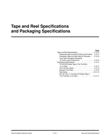
General Hard Drive Configuration ConsiderationsData/operating system (OS) on different LUNs. Backing up data on a logical unit number (LUN)separate from the OS LUN ensures that the hard drive is not splitting access and overhead betweenOS operations and backup operations. This can be accomplished by having one hard drive or diskarray contain the OS and a physically separate hard drive or disk array contain the datato be backed up.Figure 1-1. Single-Channel vs. Two-Channel BandwidthSingle Shared LUNSingle LUN withBackup dataand OSSeparate LUNsBackup DataLUNOS LUNSCSI or RAIDControllerSCSI or RAIDControllerTape DriveTape DriveHard Drive PerformanceBy design, tape drives write data sequentially and require a constant data feed to keep the driveoperating sequentially (avoiding back hitching). Conversely, hard drives are random access devices.Therefore, hard drives can sometimes struggle to provide sequential data to tape drives if that datais spread out over the drive platter. This forces the drive to continuously seek small blocks of data.Additionally, other hard drive attributes can further affect the throughput of data to the tape drive.Spindle speed. Typically measured in RPMs (revolutions per minute), the hard drive's spindlespeed determines how many times per minute the drive platter assembly can perform a fullrevolution. This has a direct effect on both random access times and sequential transfer rates.The higher the spindle speed, the faster the drive can access data.Performance Considerations for Tape Drives and Libraries7
www.dell.com support.dell.comRandom access time or seek time. Usually measured in milliseconds, seek time is the length oftime a drive's heads take to find a piece of data on the disk. The seek time of a hard disk measuresthe amount of time required for the read/write heads to move between tracks on the surface of theplatters. Because hard disks are random access devices, data can be stored on virtually any sector ofthe disk. The longer it takes to access that data, the slower the overall throughput of the drive. Thisattribute is very significant when a hard drive contains many small files. The smaller the files, themore "seeks" the drive must make to read or write the file to disk; therefore, disks tend to read orwrite very slowly when many small files are being transferred.Sequential/sustained transfer rates (STR). STR measures how fast a drive actually reads data fromand writes data to its platters. If the data being backed up is one large contiguous file, the sustainedthroughput will be close to the drive's maximum STR. However, in real-world applications, databecomes more scattered about the platter as data is deleted and written. Defragmenting a harddrive can help the drive reach its maximum STR.Buffer (cache). The buffer is the amount of memory on the drive that holds the most recentlywritten or stored data. The bigger the buffer, the more data it can hold, resulting in less timeseeking data on the disk.Hardware RAID Configuration ConsiderationsGeneral overview of RAIDThis section presents an overview of typical RAID configurations and how they affect backup andrestore rates. A RAID array is a set of hard disks that act as a single storage system or LUN. Data canbe potentially transferred through the channel of each hard drive at once, allowing for totalthroughput to be a multiple of the total number of drives in the array, minus overhead and anyredundancy as described in the following sections.In the case of a RAID configuration, the speed of the interface becomes important because thedrives share the bandwidth of the interface. For example, a single Ultra160 drive may only sustain40 MB/sec. Thus, a five-disk RAID 0 array consisting of the same drive type should be able toread/write at 200 MB/sec. However, the Ultra160 interface will limit the array to a maximum of160 MB/sec.External disk arrays, particularly in SANs, may offer significant levels of cache memory to improveI/O performance. This cache will greatly improve performance when writing to the array and maystore frequently accessed data to improve read performance. With respect to its impact on tapeperformance, the cache will mask most RAID limitations when restoring data to the array orbacking up data from the array. However, backup operations from external arrays with cache maystill feel the impact of RAID configuration limitations because the data still needs to be read fromthe disks.8Performance Considerations for Tape Drives and Libraries
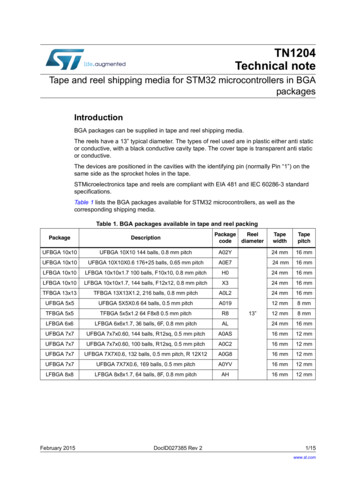
RAID 0Commonly known as striping, RAID 0 allows two or more disks to be joined to create one virtualdrive in the fashion of a single LUN. It is referred to as striping because data is written across all ofthe disks in the array, not just to one disk at a time. Thus, the throughput is spread across nchannels (n being the number of hard drives in the array) instead of a single channel for a singlehard disk. This results in excellent read/write performance, but no fault tolerance.Figure 1-2 shows four hard drives in a RAID 0 configuration. Data is striped across all four harddrives, resulting in four channels for reading and writing to the array.Figure 1-2. Example RAID 0 ConfigurationHard Drive 1 Hard Drive 2 Hard Drive 3 Hard Drive 4D Data 19D20SCSI or RAIDControllerTape DrivePerformance Considerations for Tape Drives and Libraries9
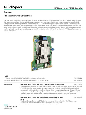
www.dell.com support.dell.comRAID 1Also known as mirroring, RAID 1 means data is written twice across two disks simultaneously. Ifone drive fails, the system switches to the other drive without losing data. During tape drivebackups, the read rate from the RAID 1 array is approximately the same as a single drive because itis reading from the primary drive. However, restore performance from the tape drive writing to theRAID 1 array can be slower due to error checking/correction (ECC) included in writing to theprimary and mirrored disks. Much of this inefficiency is due to the fact that the mirroring is oftenperformed on the CPU or RAID controller. Thus, newer RAID controllers tend to be faster due tonewer and more capable processors.Figure 1-3. Example RAID 1 ConfigurationHard Drive 1 Hard Drive 2D Data ByteM Mirrored ByteD1M1D2M2D3M3D4M4D5M5Read/WriteWrite OnlySCSI or RAIDControllerRead/WriteTape Drive10Performance Considerations for Tape Drives and Libraries
RAID 5With a RAID 5 array, data is striped across the disk array at the byte level and error correction data,or parity data, is also striped across the disk array. RAID 5 arrays tend to have very good randomread performance; this read performance generally improves as the number of disks in the arrayincreases. With the larger disk arrays, read performance can actually outperform RAID 0 arraysbecause the data is distributed over an additional drive. In additional, parity information is notrequired during normal reads.Restores from tape to a RAID 5 array tend to be nominal because it involves additional overheadfor calculating and writing the parity information.Figure 1-4. Example RAID 5 ConfigurationHard Drive 1 Hard Drive 2 Hard Drive 3 Hard Drive 4P Parity ByteD Data 6Read/WriteSCSI or RAIDControllerRead/WriteTape DrivePerformance Considerations for Tape Drives and Libraries11
www.dell.com support.dell.comIn conclusion, RAID 0 tends to be the best overall configuration for read and write performance,but does not allow for redundancy. RAID 1 is the worst performer overall, as all data written tothe array is mirrored and reads come from a single disk. RAID 5 tends to be a good read performerbut average write performer; however, RAID 5 improves if more disks are added to the array. Ifthe RAID is within an enclosure that offers significant levels of cache memory, then performancelimitations during restore operations may be abated. Backup operations will still be subject tolimitations of the RAID configuration. In addition, the characteristics of the array still dependheavily on the specific hard drive characteristics listed in "Hard Drive Performance."General Performance Considerations When Using MultipleDrives in Tape LibrariesWhen multiple tape drives are utilized simultaneously to perform data backups (such as in tapelibraries), additional aspects of the hardware configuration must be considered. By employingsimple performance-minded methods in setting up hardware and cabling configurations, additionalthroughput bottlenecks can be limited.SCSI ConfigurationsThe latest high-performance tape drives offered in tape libraries support the Ultra160 specificationof the SCSI interface standard. Therefore, to achieve maximum performance, backup serversutilizing SCSI must have an HBA installed that supports data speeds of Ultra160 or higher. A SCSIHBA that meets this requirement will allow each tape drive to communicate with the host at a rateof 160 MB/sec on the SCSI bus. The higher data rate of the SCSI bus compared to tape drivespeeds allows multiple devices to be connected to the same bus without sacrificing deviceperformance. But only to a point.The 160 MB/sec data rate of an Ultra160 bus is the maximum possible data throughput rate to alldevices connected to the bus. Therefore, a single tape drive will not consume the full bandwidth ofthe bus because it can read or write data to tape at up to 80 MB/sec (native). Multiple tape drives,however, can combine to consume the full 160 MB/sec offered by the bus if each is operating at itsmaximum native performance. Each additional drive connected to the same bus after this pointwill reduce the average performance of each drive.Therefore, to achieve maximum performance from a tape library, it is recommended to connectno more than two tape drives to each SCSI bus. See "Recommended Cabling Configurations" forspecific details and illustrations. A SCSI HBA supporting at least Ultra160 should be used, butupgrading to an Ultra320 HBA will not lead to an additional improvement in performance if thetape drive's specification is Ultra160.12Performance Considerations for Tape Drives and Libraries
SAN ConfigurationsFibre Channel (FC) offers many advantages over SCSI. First, it overcomes the distance limitationsof SCSI (12 meters for LVD SCSI versus 300 meters for a short-wave 2-Gb FC link) and allows forthe transmission of data at higher speeds. As a serial network protocol rather than a bus-basedarchitecture like SCSI, FC has also become the protocol of choice for the implementation of SANs,allowing for the consolidation of data storage resources. In addition, each FC connection is madeup of a transmit link and a receive link, allowing for full-duplex operation. This means that data canbe transmitted in two directions simultaneously. Therefore, during a backup operation across asingle FC connection, data can be read from a source and written to tape without taking turns incommunication, effectively doubling the bandwidth of a connection. See Figure 1-5.Figure 1-5. Fibre Channel Link Diagram2 Gb 200 elDevice2 Gb 200 MB/secWhen setting up tape libraries in a SAN, performance can still be affected by various factors. Thesefactors include FC link speeds, data flow between the source and tape library, and performancelimitations of external storage arrays. With an understanding of the overall setup and managementof the solution, many of these factors can be avoided.Even with the high data bandwidth offered by the FC protocol in SANs, proper considerationsmust be made for tape drives in order to avoid a situation in which the FC link may limitperformance. The data rate of a 2-gigabit (Gb) FC link is 200 MB/sec (that is, 200 MB/sec on thetransmit link and 200 MB/sec on the receive link). Therefore, attempting to operate multiple tapedrives across the same link can potentially exceed the full bandwidth of a link. If the host isoperating with a legacy 1-Gb adapter, backing up data to two drives may be sufficient to revealsignificant performance limitations.Therefore, when using three or more tape drives simultaneously on a 2-Gb link, you may need todistribute the backups across a number of connections, rather than relying on a single link. This iswhere understanding the SAN solution's topology is beneficial. Following the data path during abackup operation as it is read from the source and then written out to tape will help administratorsrecognize any potential bottlenecks. If any bottlenecks are identified, measures may be takendepending on the configuration. For example, if the backup solution requires multiple drives to bein operation at once, splitting the tape hardware across separate fabrics may improve performanceby splitting the connections. See Figure 1-6.Performance Considerations for Tape Drives and Libraries13
www.dell.com support.dell.comFigure 1-6. Single vs. Split Data Flow to Tape LibraryHOSTHOSTFibre ChannelSwitchTape LibraryFibre ChannelDisk ArrayFibre ChannelSwitchFibre ChannelSwitchTape LibraryFibre ChannelDisk ArrayAt the same time, if a bottleneck exists in the data being read from an external FC disk array, theuse of I/O management software such as EMC PowerPath with an additional fabric connectionwill automatically load-balance the data across multiple paths and increase availability throughpath failover. See Figure 1-7. The left side of the figure represents a SAN disk array in which all ofthe data is forced through a single link, creating a bottleneck that slows data flow to the tapehardware. The right side shows how load balancing doubles the I/O bandwidth coming out of thearray by allowing the data to transmit across two links.14Performance Considerations for Tape Drives and Libraries
Figure 1-7. Bottlenecked Data Flow vs. Load-Balanced Disk ArrayHOSTHOSTFibre ChannelSwitchFibre ChannelSwitchFibre ChannelSwitchFibre ChannelSwitchTape LibraryFibre ChannelDisk ArrayTape LibraryFibre ChannelDisk ArrayFinally, FC disk arrays on the SAN can also experience the same performance limiters described in"Hard Drive and RAID Array Configuration." Therefore, improving the performance characteristicsof the disk arrays will also have a direct effect on backup speed across the SAN.SAN Configurations Utilizing the Library Fibre Channel BridgeCertain tape libraries may be connected to a SAN by way of a Fibre Channel bridge module. Themodule acts as a bridge between the SCSI and FC protocols and provides additional management,security, and operational features unavailable in most native FC libraries. For details on thesefeatures, see the Fibre Channel bridge User's Guide for your tape library.In some tape library configurations, the Fibre Channel bridge module may act as a bottleneck anddecrease performance of tape drives. This is because the processing capability in the Fibre Channelbridge module required to bridge the SCSI and FC communication cannot meet the aggregatedata throughput offered by certain multidrive configurations. Despite this, most data backupsolutions will not experience the Fibre Channel bridge module as the primary limiting factor intape performance. Dedicated backup servers will frequently encounter a situation where thelimitations at the host will be compounded by the exertion of feeding data to multiple tape drives.This results in average drive performance below the level where the Fibre Channel bridge modulebecomes a factor.Performance Considerations for Tape Drives and Libraries15
www.dell.com support.dell.comRecommended Cabling ConfigurationsSCSI Cabling to the HostTape Library With up to Six Tape DrivesWhen the tape library is SCSI-attached to a host, ensure that no more than two drives are on asingle bus. Additional SCSI controllers are required for libraries with five or six tape drives toensure that no SCSI bus becomes a barrier to maximizing throughput.Figure 1-8. SCSI Cabling for Library With up to Six Tape Driveslibrary-to-hostSCSI cableterminatorterminatorlibrary-to-hostSCSI cabledrive-to-librarycontroller SCSIcableTape Library With up to Two Tape DrivesThe drives in a fully configured two-drive tape library can be cabled to a host on the same SCSI buswithout encountering significant limitations to backup performance. The backup rates for twodrives on a single SCSI bus will match the backup rates for two drives on separate buses. However,customers who enable the verify feature in backup applications may wish to improve the verifyperformance by splitting two drives onto two SCSI buses. By doing so, verify performance mayimprove by up to 25 percent.16Performance Considerations for Tape Drives and Libraries
Figure 1-9. SCSI Cabling for Library With up to Two Tape DrivesterminatorCabling Drives to the Fibre Channel BridgeFigures 1-10 through 1-17 illustrate how a tape library with up to six drives should be configuredwith a Fibre Channel bridge module in order to optimize tape performance over FC.Performance Considerations for Tape Drives and Libraries17
www.dell.com support.dell.comFigure 1-10. Fibre Channel Bridge Cabling With One Tape Drivelibrary SCSIinterfaceterminatordrive 1SCSI 118Performance Considerations for Tape Drives and Libraries
Figure 1-11.Fibre Channel Bridge Cabling With Two Tape Driveslibrary SCSIinterfaceterminatordrive 2terminatordrive 1SCSI 1SCSI 2Performance Considerations for Tape Drives and Libraries19
www.dell.com support.dell.comFigure 1-12. Fibre Channel Bridge Cabling With Three Tape Driveslibrary SCSIinterfaceterminatordrive 3drive 2SCSI 1SCSI 220Performance Considerations for Tape Drives and Librariesterminatordrive 1
Figure 1-13.Fibre Channel Bridge Cabling With Four Tape Drivesterminatorlibrary SCSIinterfacedrive 4drive 3terminatordrive 2SCSI 1drive 1SCSI 2Figure 1-14.Channel Zoning Settings for Tape Library With One to Four DrivesPerformance Considerations for Tape Drives and Libraries21
www.dell.com support.dell.comFigure 1-15. Fibre Channel Bridge Cabling With Five Tape Drivesterminatorlibrary SCSIinterfacedrive 5drive 4SCSI 3terminatordrive 3SCSI 4SCSI 1drive 2terminatordrive 1SCSI 222Performance Considerations for Tape Drives and Libraries
Figure 1-16.Fibre Channel Bridge Cabling With Six Tape Drivesterminatordrive 6terminatorlibrary SCSIinterfacedrive 5drive 4SCSI 3terminatorSCSI 4drive 3drive 2SCSI 1terminatordrive 1SCSI 2Figure 1-17.Channel Zoning Settings for Tape Library With Five or Six DrivesPerformance Considerations for Tape Drives and Libraries23
www.dell.com support.dell.comFigure 1-18 and Figure 1-19 illustrate how a tape library with up to two tape drives should beconfigured with a Fibre Channel bridge module in order to optimize tape performance over FC.Figure 1-18. Tape Library With One DriveterminatorFigure 1-19. Tape Library With Two Drivesterminator24terminatorPerformance Considerations for Tape Drives and Libraries
Dell PowerVault �事项w w w. d e l l . c o m s u p p o r t . d e l l . c o m
�知。 2005 Dell Inc. 版权所有,翻印必究。未经 Dell Inc. �本文中使用的商标:Dell、DELL 徽标和 PowerVault 是 Dell Inc. 的商标; EMC 和 PowerPath 是 EMC Corporation ��公司或其制造的产品。Dell Inc. 005 年 6 月
目录简介. . . . . . . . . . . . . . . . . . . . . . . . . . . . . . . . . . . . . . .主机备份一般注意事项. . . . . . . . . . . . . . . . . . . . . . . . . . . .磁带驱动器和数据注意事项 .硬盘驱动器和 RAID 阵列配置. . . . . . . . . . . . . . . . . . . . . . . . . . . . . . . . . . . . . . . . . . ��般性能注意事项SCSI 配置 .SAN 配置 . . . . . . . . . . . . . . . . . . . . . . . . . . . . . . . . . . . . . . . . . . . . . . . . . . . . . . . . . . . . . . . . . . . . . . . . .29292930363636目录27
28目录
许多主机方面的因素,如 RAID(廉价 [ 或独立 ] ��注意事项同时适用于 SCSI 和存储区域网络 (SAN) CSI 命令所带来的额外开销。SCSI �所有 SCSI 率。例如,驱动器可能以 80 MB/ �度仅为 77 MB/ ��驱动器,64 KB 块大小低于 64 间就越少;但这样可能会影响内存和 CPU ��。始终确保 SCSI �的驱动程序和固件。请访问 support.dell.com,为您的 Dell PowerVault �在各个主机总线适配器 (HBA) 方法是保持磁带驱动器 HBA 与硬盘驱动器 HBA �板载双模式 SCSI/RAID �须在 RAID �息。有关 RAID �阅“硬件 RAID �储库性能注意事项29
www.dell.com �块损坏的机率就会增加。一片 LTO 介质的典型寿命大约为75 �的 LTO 过程称为“后系留”)。例如,Dell PowerVault 110T (LTO2 和 LTO3)磁带驱动器在向 LTO-3 介质写入数据时,将速率匹配为最低 30 MB /秒。如果主机服务器仅以 20 MB ��在这种情况下,有效的吞吐量将低于 20 MB /秒(可能接近 15 MB t 110TLTO-2 和 LTO-3(固件 53XX 或更高版本)提供了一个诊断模式 ��断测试的一部分,诊断模式 "F" 驱动器和 RAID ��不同 LUN 上的数据/操作系统 (OS)。在与操作系统 LUN 不同的逻辑设备号 (LUN) 库性能注意事项
图 1-1. 单信道与双信道带宽单个共享的 LUN单一 LUN 用于备份数据和操作系统独立的 LUN操作系统 LUNSCSI 或 RAID控制器SCSI 或 ��据 �器的数据吞吐量。转速。通常以 �头在磁盘上查找数据所用
for your Dell PowerVault tape product. 6 Performance Considerations for Tape Drives and Libraries www.dell.com support.dell.com Attach tape drives and hard drives on separate controllers (internal or external) on separate host bus adapters (HBAs). This depends somewhat on the performance capabilities of your controller,