Transcription
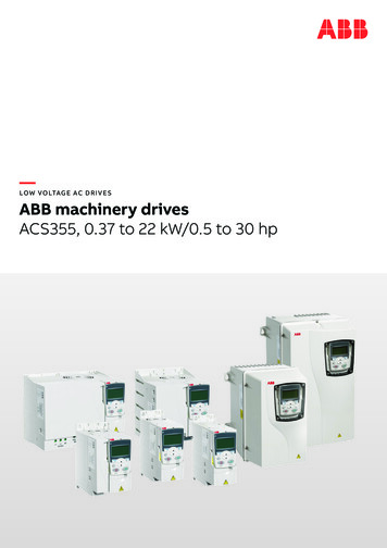
—LOW VO LTAG E AC D R I V E SABB machinery drivesACS355, 0.37 to 22 kW/0.5 to 30 hp
2A B B M A C H I N E R Y D R I V E S , A C S 3 5 5 , C ATA LO G—All your machine building needsin one drive. ACS355 drives.
3—Table of contents04 – 05 Introduction to ACS35506 – 07 Little big drives without limiting your business08 Typical applications09 How to select a drive10 Ratings and types11 Technical data12 – 13 Dimensions and weights14 Cooling and fuses15 Control connections16 – 17 Control program example18 – 19 Control program variants20 – 21 Product variants22 – 30 Options31 Compact PLC and AC drive starter kit32 – 33 ABB automation products34 – 37 Drives service
4A B B M A C H I N E R Y D R I V E S , A C S 3 5 5 , C ATA LO G—Introduction to ACS355ABB machinery drivesThe ABB machinery drives are designed to befast drives to install, parameter-set andcommission. Thus saving hours of engineeringwork. They are highly compact and cost-effective.Equipped with cutting-edge intelligence andsafety capability the drives are designedspecifically to meet the production andperformance needs of system integrators,original equipment manufacturers (OEMs) andpanel builders, as well as the requirements ofend users in a broad range of applications.In the ABB machinery drives portfolio, ACS355represents the micro drive range; meetingrequirements like compact size, being optimizedfor a lower power range, cost-effectiveness,and ease of use. By choosing an ABB machinerydrive, machine builders not only get all the cleverthings inside the drive, but also everythingoutside it: the entire global ABB. This means afull range of products and services designedto support their business.ApplicationsABB machinery drives are designed to meetthe requirements of an extensive range ofmachinery applications. The drives are idealfor food and beverage, material handling, lifting,textile, printing, rubber and plastics, andwoodworking applications.Highlights Exceptionally compact drives anduniform design Quick commissioning with application macrosand panel assistants Safe torque off function (SIL3) as standard Sensorless vector control for induction motorsand permanent magnet motors up to 599 Hz Built-in braking chopper IP66 product variant for harsh environmentsand solar pump drive variant available
I N T R O D U C T I O N TO A C S 3 5 55
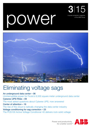
6A B B M A C H I N E R Y D R I V E S , A C S 3 5 5 , C ATA LO G—Little big drives without limitingyour businessACS355 drives are designed to maximize your machine’s availabilitywith drives that are easy to install and setup.The drive is highly modular and supports avariety of fieldbus protocols thus providingflexible connectivity. In addition to a broadrange of built-in options such as differentI/O and communications, a wide selectionof external accessories is also available.Wherever your machine is located, thelocal ABB will be there to support youand your clients.Flexible performanceReduce the need for external PLCcomponents with built-in sequenceprogramming providing simpledrive control logic. Improve productionflow and increase cost savings withbuilt-in features, such as speedcompensated stop enabling precisionstopping, and patented smooth start forpermanent magnet motors.Quick and easy commissioningPredefined I/O configurations for applicationmacros and built-in assistants speed upcommissioning of the drive, allowing you toconcentrate on your business.Compact and uniform designCompact size, the broadest power range inits class from 0.37 to 22 kW and side-by-sidemounting ensure optimized cabinet installationin a wide range of machinery applications,resulting in space and cost savings.Supported motor typesSame drive can be used for sensorlessinduction and permanent magnet motorcontrol without a feedback device.
L I T T L E B I G D R I V E S W I T H O U T L I M I T I N G YO U R B U S I N E S SApplication-specific product variantsEnsure long life time of equipment and reliableenergy supply with a drive for solar pumpsincluding embedded pump-specific featuresprotecting the pump. The high speed variant forspindle applications provides speed controllertuning without use of encoder.Protection against harsh environmentsIncrease time and cost savings with NSF certifiedproduct variant for IP66/67/69K, UL Type 4Xprotection classes with no need to design specialenclosures for applications that require a highingress protection against dirt, dust andmoisture.Communication withmajor automation networksOptional fieldbus adapters enableconnectivity with major industrialautomation networks.SafetyIntegrated safe torque off (STO) function up toSIL 3 is a cost-effective and certified solution forsafe machine maintenance by fulfilling IEC 61508,EN 62061 and EN ISO 13849-1 standards. Thesafety function can also be used to implementEmergency Stop without contactors.Remote monitoringWith a built-in web server and stand alonedatalogger, available remote monitoring optionsenables worldwide and secure access to drives.7
8A B B M A C H I N E R Y D R I V E S , A C S 3 5 5 , C ATA LO G—Typical applicationsMixerIn mixing applications the drive provides a highstarting torque. The silent operation modeadjusts the switching frequency of the drive to ahigher level after the high-torque start, resultingin lower audible noise. The FlashDrop toolprovides a quick and safe way to configuremultiple drives for identical mixer applications.ConveyorProduction lines often have multiple stages,including conveyors, which need to be efficientlylinked with each other to provide high productionoutput. A drive provides smooth start and stop ofthe conveyor, thereby reducing mechanicalstress and lowering maintenance costs.Packaging machinePackaging machines often require a drive toprovide a high degree of repeatability andaccuracy during the packing operation. As such,the ACS355 is well suited for packaging dutiesand also provides good dynamic and static speedcontrol accuracy. Sequence programming enablesthe drive to perform sequences of tasks, reducingthe need for a PLC. Software features includetimer, counter, brake control and jogging – all ofwhich can be used in a packaging machine.Bottling lineWhen filling the bottles with liquid, bottling linesrequire a drive which offers high accuracy. TheACS355 is perfect for this purpose, with its gooddynamic and static speed control. When dealingwith liquids, the ACS355 with a high protectionclass (IP66) would also be a good choice.WindersThe ACS355 offers high static speed accuracy.When dealing with thin strings like in stringwinders, it is essential to control the winderspeed accurately in order to prevent the stringsfrom snapping. Surface winders, on the otherhand, require high static speed accuracy to keepcontrol of the material thickness or tension.
9—How to select a driveThe right drive is extremely easy to select. The following instructionsshow you how to order the right drive for your application.Start by identifying the required drive variant andyour supply voltage and select the related ratingtable. Or use ABB’s DriveSize dimensioning tool.A B B M A C H I N E R Y D R I V E S , A C S 3 5 5 , C ATA LO G101—Ratings and typesRatings IP20/UL Opentype/ NEMA 1 optionPN(kW)Select your drive’s order code (drive type) fromthe rating table based on the load current, or, if itis unknown, select the drive based on yourmotor’s power and current ratings.PN(hp)Type designationFramesizeIP20ACS355-01X-02A4-2R0-R1-I 2N(A)FramesizeIP661-phase AC supply, 200 to 240 V0.3720.50.751.02.44.76.7 R2-3-phase AC supply, 200 to 240 V 3X-01A2-4R0ACS355-03X-01A9-4R0R1R1R1-R1R13-phase AC supply, 380 to 480 ACS355-03X-03A3-41.52.0A B B M A C H I N E R Y D R I V E S , A C S 3 5 5 , C ATA LO -03X-08A8-4R1R17.512.55.5—Ratings and types .020.031.0ACS355-03X-31A0-4R4-7.5Type designationThis is the unique reference number (shown incolumn 4, right) that clearly identifies your driveby current rating and frame size. Once the drive’stype designation has been selected, the framesize (column 5) can be used to determine thedrive dimensions, shown on page 355-03X-44A0-4R4-VoltagesACS355 is available in two voltage ranges:2 200 to 240 V4 380 to 480 VInsert either “2” or “4”, depending on your chosenconstruction, current rating, voltage, and optionand variant codes into the type designation.Current ratingCurrent rating represents the rated continuousdrive output current inside the drivespecification. Motor power stated in the tablebelow states the typical motor power.Variant codeThis code states the factory installed SW variantsto the drive. See pages 16 - 19 for details.Construction“01E” within the type designation variesdepending on the drive phase and EMC filtering.Choose below the one you need.01 1-phase03 3-phaseE EMC filter connected, 50 Hz frequencyU EMC filter disconnected, 60 Hz frequency(In case the fi lter is required it can easilybe connected)X within the type designation stands for E or U.P N for kW Typical motor power in 400 V at normal useP N for hp Typical motor power in 460 V at normal useI 2N for A Continuous rms current. 50% overload is allowed forone minute in ten minutes.Ratings IP20/UL Opentype/ NEMA 1 optionPN(kW)PN(hp)Type designationI 2N(A)FramesizeIP201-phase AC supply, 200 to 240 V0.370.50.751.02.44.76.7FramesizeIP66 09.8ACS355-01X-09A8-2R2R13-phase AC supply, 200 to 240 V X-31A0-2R4-11.015.046.2ACS355-03X-46A2-2R43-phase AC supply, 380 to 480 V0.370.50.550.751.2 -05A6-4R1R12.25.55.6Type designationThis is the unique reference number (shown incolumn 4, right) that clearly identifies your driveby current rating and frame size. Once the drive’stype designation has been selected, the framesize (column 5) can be used to determine thedrive dimensions, shown on page 4R4-VoltagesACS355 is available in two voltage ranges:2 200 to 240 V4 380 to 480 VInsert either “2” or “4”, depending on your chosenconstruction, current rating, voltage, and optionand variant codes into the type designation.Current ratingCurrent rating represents the rated continuousdrive output current inside the drivespecification. Motor power stated in the tablebelow states the typical motor power.A B B M A C H I N E R Y D R I V E S , A C S 3 5 5 , C ATA LO G22—OptionsVariant codeThis code states the factory installed SW variantsto the drive. See pages 16 - 19 for details.Construction“01E” within the type designation variesdepending on the drive phase and EMC filtering.Choose below the one you need.01 1-phase03 3-phaseE EMC filter connected, 50 Hz frequencyU EMC filter disconnected, 60 Hz frequency(In case the fi lter is required it can easilybe connected)Selecting optionsThe options shown in the table are availablewithin the ACS355 range. The ordering code,which is shown in the second column,X within the type designation stands for E or U.P N for kW Typical motor power in 400 V at normal useP N for hp Typical motor power in 460 V at normal useI 2N for A Continuous rms current. 50% overload is allowed forone minute in ten minutes.OptionsOrderingcodeDescription*)Protection classControl panel(choose one option only)MUL1-R4B063IP66/IP67/UL type 4X enclosureJ400Assistant control panelJ404Basic control panelACS-CP-C–*)Panel mounting kitACS/H-CP-EXT–*)Panel holder mounting NetTMFDNA-01K452LonWorks FLON-01K454PROFIBUS DPFPBA-01K457CANopen FCAN-01Extension modules(choose one option only)Modbus RTUFMBA-01K462ControlNetTMFCNA-01K4661 port EtherNet/IP TM, Modbus TCP,PROFINET IOFENA-01K469EtherCAT FECA-01*)RS-485/ModbusFRSA-00K470POWERLINKK4731 port EtherNet/IP TM, Modbus TCP,PROFINET IO2 port EtherNet/IP TM, Modbus TCP,PROFINET IOFENA-21*)20 pack PROFIBUS DP for machinery drivesFPBA-01-M*)20 pack CANopen for machinery drivesFCAN-01-ML502Speed encoder moduleRelay output moduleMREL-01Auxiliary power extension moduleMPOW-01*)Remote monitoring adapterSREA-013AUA0000094517Remote monitoring adapterNETA-21Cable gland kit (IP66/IP67/UL Type 4X)–F278Input switch kit (factory installed variant)–C169Pressure compensation valve*)MFDT-01DriveWindow LightDriveWindow LightPLC and AC drive starter kit*)Input chokesProduct seriesTypes and constructionRatingVoltageOptionsX XXXX Option, external– Not available1)EMC filters1)Braking resistors*)––FlashDrop tool*)P924 **)*)0XAX––H376*)– 0XX ––MTAC-01L511G406External options Standard Product (choose one option only)Pressure compensationDrive type:––ACS-CP-APotentiometerHigh protection class options3IP66/67driveMUL1-R3NEMA 1/UL type 1 (R4)Remote monitoring2AvailabilityIP20driveMUL1-R1NEMA 1/UL type 1 (R3)K4583ModelNEMA 1/UL type 1 (R0, R1, R2)*)*)Panel mounting kitChoose your options and add the option codesto the drive’s order code. Remember to use a “ ”mark before each option code.replaces the XXXX in the type designation.You can order as many options asrequired, simply by extending the codeas necessary.1)Output chokes* To be ordered as a separate item.**) Available in selected countries.)1)1)External options not available inIP66/IP67/UL Type 4X protection class.
A B B M A C H I N E R Y D R I V E S , A C S 3 5 5 , C ATA LO G10—Ratings and typesRatings IP20/UL Opentype/ NEMA 1 optionPN(kW)PN(hp)Type designationI 2N(A)FramesizeIP201-phase AC supply, 200 to 240 VFramesizeIP66 -3-phase AC supply, 200 to 240 V 03X-01A2-4R03-phase AC supply, 380 to 480 V ACS355-03X-44A0-4R4-X within the type designation stands for E or U.P N for kW Typical motor power in 400 V at normal useP N for hp Typical motor power in 460 V at normal useI 2N for A Continuous rms current. 50% overload is allowed forone minute in ten minutes.Type designationThis is the unique reference number (shown incolumn 4, right) that clearly identifies your driveby current rating and frame size. Once the drive’stype designation has been selected, the framesize (column 5) can be used to determine thedrive dimensions, shown on page 12.VoltagesACS355 is available in two voltage ranges:2 200 to 240 V4 380 to 480 VInsert either “2” or “4”, depending on your chosenconstruction, current rating, voltage, and optionand variant codes into the type designation.Current ratingCurrent rating represents the rated continuousdrive output current inside the drivespecification. Motor power stated in the tablebelow states the typical motor power.Variant codeThis code states the factory installed SW variantsto the drive. See pages 16 - 19 for details.Construction“01E” within the type designation variesdepending on the drive phase and EMC filtering.Choose below the one you need.01 1-phase03 3-phaseE EMC filter connected, 50 Hz frequencyU EMC filter disconnected, 60 Hz frequency(In case the fi lter is required it can easilybe connected)
11—Technical dataProduct complianceMains connectionVoltage andpower rangeFrequency1-phase, 200 to 240 V 10%0.37 to 2.2 kW (0.5 to 3 hp)3-phase, 200 to 240 V 10%0.37 to 11 kW (0.5 to 15 hp)3-phase, 380 to 480 V 10%0.37 to 22 kW (0.5 to 30 hp)48 to 63 HzProgrammable control connectionsCommon DC connectionVoltage andpower rangeLow Voltage Directive 2006/95/ECMachinery Directive 2006/42/ECEMC Directive 2004/108/ECQuality assurance system ISO 9001Environmental system ISO 14001UL, cUL, CE, C-Tick and GOST R approvalsRoHS compliant230 V drives, 325 V 15%400/480 V drives, 540 15% (commonDC manual)Pmax Pn of the driveMotor connectionVoltage3-phase, from 0 to U SUPPLYFrequency0 to 599 HzContinuous loadingcapability(constant torque at a max.ambient temperature of 40 C)Rated output current I 2NOverload capacity1.5 x I 2N for 1 minute every 10 minutes(at a max. ambient temperature At start 1.8 x I 2N for 2 sof 40 C)Switching frequencySelectableDefault 4 kHz4 to 16 kHz with 4 kHz stepsAcceleration time0.1 to 1800 sDeceleration time0.1 to 1800 sBrakingBuilt-in brake chopper as standardSpeed controlStatic accuracyDynamic accuracy20% of motor nominal slip 1% s with 100% torque stepTorque controlTorque step rise timeNon-linearity 10 ms with nominal torque 5% with nominal torqueEnvironmental limitsTwo analog inputsVoltage signalUnipolarBipolarCurrent signalUnipolarBipolarPotentiometer reference valueResolutionAccuracy0 (4) to 20 mA, R in 100 Ω-20 to 20 mA, R in 100 Ω10 V 1% max. 10 mA, R 10 kΩ0.1% 2%One analog output0 (4) to 20 mA, load 500 ΩAuxiliary voltage24 V DC 10%, max. 200 mAFive digital inputsInput impedance12 to 24 V, PNP and NPN, programmableDI5 0 to 16 kHz pulse train2.4 kΩOne relay outputTypeMaximum switching voltageMaximum switching currentMaximum continuous currentNO NC250 V AC/30 V DC0.5 A/30 V DC; 5 A/230 V AC2 A rmsOne digital outputTypeMaximum switching voltageMaximum switching currentFrequencyResolutionAccuracyTransistor output30 V DC100 mA/30 V DC, short circuit protected10 Hz to 16 kHz1 Hz0.2%0 (2) to 10 V, R in 312 kΩ-10 to 10 V, R in 312 kΩSerial and Ethernet communicationAmbient temperature-10 to 40 C (14 to 104 F), no frostallowed50 C (122 F) with 10% deratingFieldbusesRefresh ratePlug-in type 10 ms (between drive andfieldbus module)AltitudeRated current available at 0 to 1000 m.In altitudes from 1000 to 2000 m(3300 to 13,200 ft) above sea level, thederating is 1% for every 100 m (330 ft).If the installation site is higher than2000 m (6600 ft) above sea level,please contact your local ABBdistributor or office for furtherinformation.DeviceNetTM5-pin screw type connector,up to 500 kbit/s baud ratePROFIBUS DP9-pin D-connector, up to 12 Mbit/sbaud ratePOWERLINK2 pcs RJ-45 connector, 100 Mbit/sbaud rateControlNetTM2 pcs 8P8C modular jacksCANopen 9-pin D-connector, up to 1 Mbit/sModbus RTU4-pin screw type connector,up to 115 kbit/s baud rateEtherNet/IPTM, ModbusTCP, PROFINET IO1 RJ45 connector (FENA-01 and -11) or2 RJ45 connectors (FENA-21).10/100Mbit/s baud rateLonWorks 3-pin screw type connector,up to 78 kbit/s baud rateEtherCAT 2 pcs RJ-45 connectors,100 Mbit/s baud rateRelative humidityLower than 95% (withoutcondensation)Degree of protectionIP20/optional NEMA 1/UL type 1enclosureIP66/IP67/UL Type 4X as an option upto7.5 kW, IP69K available for IP66/IP67variant with compatible cable glandsEnclosure colourNCS 1502-Y, RAL 9002, PMS 420 CContamination levelsIEC721-3-3No conductive dust allowedClass 1C2 (chemical gases)Class 1S2 (solid particles)Class 2C2 (chemical gases)Class 2S2 (solid particles)Class 3C2 (chemical gases)Class 3S2 (solid particles)TransportationStorageOperationChokesAC input chokesExternal option. For reducing THD inpartial loads and to comply withEN/IEC 61000-3-12.AC output chokesExternal option. To achieve 2x longermotor cables
A B B M A C H I N E R Y D R I V E S , A C S 3 5 5 , C ATA LO G12—Dimensions and weightsCabinet-mounted drives (IP20/UL Open)FramesizeIP20/UL OpenH1(mm)H2(mm)H3(mm)W(mm)D1(mm)D2 52.5R41812022442601691954.4H1H2H3H1 Height without fastenings and clamping plateH2 Height with fastenings but without clamping plateH3 Height with fastenings and clamping plateW WidthD1 Standard depthD2 Depth with MREL, MPOW or MTAC optionD1D2WWall-mounted drives (NEMA 1/UL Type 1)FramesizeNEMA 1/UL Type 2602991691771953.1R42703202601771955.0H4H5H4 Height with fastenings and NEMA 1 connection boxH5 Height with fastenings, NEMA 1 connection box and hoodW WidthD1 Standard depthD2 Depth with MREL, MPOW or MTAC optionD1D2WWall-mounted drives (IP66/IP67/UL Type 4X)Frame sizeIP66/IP67/UL Type 627713H HeightW WidthD1 Standard depthHD1W
DIMENSIONS AND WEIGHTS13
A B B M A C H I N E R Y D R I V E S , A C S 3 5 5 , C ATA LO G14—Cooling and fusesCoolingACS355 is fitted with cooling fans as standard. The coolingair must be free from corrosive substances and must not beabove the maximum ambient temperature of 40 C (50 Cwith derating). Heat dissipation from IP66/IP67/UL Type 4Xdrive equals to the IP20 UL Open values. For more specificlimits see the Technical specification – Environmental limitsin this catalog.FusesStandard fuses can be used with ABB machinery drives.For input fuse connections see table below. Also ManualMotor Protectors can be used to protect the installation.See user’s manual for details.Cooling air flowSelection tableType designationFramesizeHeat dissipationAir flow(W)BTU/hr1)3Type designationIEC fuses3m /h ft /minUL fuses(A)Fuse)type*(A)Fuse)type*1-phase AC supply, 200 to 240 V1-phase AC supply, 200 to 240 V2)ACS355-01X-02A4-2R010gG10 UL class T2414ACS355-01X-04A7-2R116gG20 UL class T3332414ACS355-01X-06A7-2R116/201)gG25 UL class T1013432112ACS355-01X-07A5-2R220/251)gG30 UL class T1244222112ACS355-01X-09A8-2R225/351)gG35 UL class T10 UL class 1X-09A8-2R22)–3-phase AC supply, 200 to 240 V3-phase AC supply, 200 to 240 -03X-02A4-2R010gG2)–2)ACS355-03X-03A5-2R010gG10 UL class T14ACS355-03X-04A7-2R110gG15 UL class 116gG15 UL class gG15 UL class 6gG20 UL class 5gG30 UL class 5gG35 UL class 3gG60 UL class 80gG80 UL class 100gG100 UL class T10 UL class T3-phase AC supply, 380 to 480 V3-phase AC supply, 380 to 480 3X-01A9-4R010gG10 UL class G10 UL class G10 UL class G15 UL class gG15 UL class 6gG20 UL class 0gG25 UL class 5gG30 UL class 5gG35 UL class 50gG50 UL class 80gG80 UL class 100gG100 UL class 100gG100 UL class TX within the type designation stands for E or U.1)BTU/hr British Thermal Unit per hour. BTU/hr isapproximately 0.293 Watts.2)Frame size R0 with free convection cooling.X within the type designation stands for E or U.*) According to IEC-60269 standard.1)If 50% overload capacity is needed, use the bigger fuse alternative.Free space requirementsEnclosure typeSpace above(mm)Space below(mm)Space on left/right(mm)All frame sizes75750IP66/67 enclosure757520
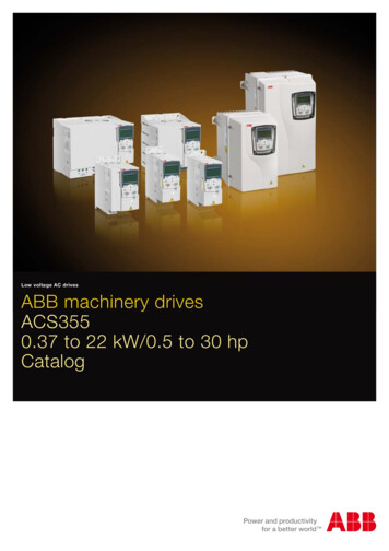
15—Control connectionsControl panel (RJ-45)Modbus RTU (RS-232)ScreenSCRmax 500 ohmAI11 - 10 kohmAnalog input circuit commonGNDReference voltage 10 V DC, max 10 mA 10 VROCOMRONCAnalog input circuit commonGNDAux. voltage output 24 V DC, max. 200 mA 24 VDigital input commonDCOMPROGRAMMABLEDIGITALINPUTS (ABB Standardmacro defaults shown)DI1Stop/StartForward/ReverseDI2Constant speed selectionDI3Constant speed selectionDI4Acceler. anddeceler. selection 1)DI51) DI5 can also be usedas a frequency input.3-phase power supplyRONOPROGRAMMABLE RELAYAND DIGITAL OUTPUTSRelay output250 V AC / 30 V DC /2 ArmsDOSRCGNDAux. voltage output commonOutput frequency 0-20 mAAnalog output circuit commonGNDmAVAI2Not in use by defaultAOAI1AI2Output frequency/speedreference, 0 - 10 VDOOUTDOGNDDigital output, PNP transistor type30 V DC, max. 100 mAABB machinery drives haveeight application macros: ABB standard macro Torque control macro 3-wire macro Alternate macro AC500 Modbus macro Motor potentiometermacro Hand/auto macro PID control macroSafety SwitchX1C:STOOUT1OUT2IN1IN2EMCEMC filter grounding screwVARVaristor grounding screwU2L1U1L2V1 Brake chopper V2L3W1BRK BRK-AC motorW2Optional brake resistor or DC power connection—Sinking DI configuration (NPN connected)ConstSpeed 1Fwd /RevStart /StopIn addition to the standardmacros the user can createthreeuser macros. The usermacro allows the user tosave the parameter settingsfor later use.—Sourcing DI configuration (PNP connected) with external power supplyACS355: X1Ramppair selApplication macrosApplication macros arepreprogrammed parametersets. While starting up thedrive, the user typicallyselects one of the macrosthat is best suited for theapplication. The diagrambelow gives an overview ofACS355 control connectionsand shows the default I/Oconnections for the ABBstandard macro. 24 VConstSpeed 1 24 VGNDACS355: X1Fwd /RevStart /Stop 24 VGNDDCOMDCOMDI1DI1DI2DI2DI3DI3DI4DI50VDI4DI5
16A B B M A C H I N E R Y D R I V E S , A C S 3 5 5 , C ATA LO G—Control program exampleThe ACS355 drives have many solutions forcommon challenges. The following exampleexplains how the COUNTER STOP functionoperates within a conveyor unloading routine.The function stops the conveyor after apredefined number of boxes have passed thesensor.The operator starts the conveyor by activatingthe drive using switch, S. The switch is connectedto digital input 1 (DI1). The drive accelerates to aconstant speed of 30 Hz with a 1 second ramptime.Meanwhile a sensor, or proximity switch, P, isconnected to digital input 5 (DI5). This sensorgenerates one pulse, every time a box on theconveyor passes by. When the required number ofboxes – in this case 20 – have passed the sensor,the drive stops with a 1 second ramp time.Parameter settingsStartup dataThe correct motor parameters are set withinparameter group 99. However, if the current andvoltage settings of the motor and drive match,this is not necessary. The ACS355 also featuresvector control, which can be used by setting therelevant parameters and undertaking an ID run.Start/Stop/Direction logicParameter 1001 EXT1 COMMANDS is set toCOUNTER STOP [24]. Under certain conditionsthe counter output will modify the start/stopsignal for stopping.Constant speed selectionParameter 1201 CONST SPEED SEL is set to DI1 [1].Parameter 1202 CONST SPEED 1 acts as a speedreference source when digital input 1 is active.Parameter 1202 CONST SPEED 1 is set to 30 Hz.Start/Stop functionsParameter 2101 START FUNCTION is set toAUTO [1], which is also the default value. If hightorque is required for the conveyor to start,settings DC MAGN [2] can be used.Parameter 2102 STOP FUNCTION is set toRAMP [2]. Thus the drive ramps down to 0 at astop ET1908RESET nVALUE0166Counter parametrizationParameter 1904 COUNTER ENABLE is set toDI1 [1]. Counter is enabled now by digital input 1.When digital input 1 is low, the counter is notcounting.Parameter 1905 COUNTER LIMIT is set to 20.In this example the loading station can only hold20 boxes.Parameter 1906 COUNTER INPUT is set toPLS IN (DI5) [1] which is also the default value.Pulse counter P is wired to digital input (DI5).This digital input can also handle high fr
Little big drives without limiting your business ACS355 drives are designed to maximize your machine's availability with drives that are easy to install and setup. The drive is highly modular and supports a variety of fieldbus protocols thus providing flexible connectivity. In addition to a broad range of built-in options such as different