Transcription
1ICAP: Designing Inrush Current Aware PowerGating Switch for GPGPUHadi Zamani‡ , Devashree Tripathy‡ , Ali Jahanshahi‡ , Daniel Wong‡ ‡ University of California, Riverside, CA, USA{hzama001, dtrip003, ajaha004, danwong}@ucr.eduAbstract—The leakage energy of GPGPU can be reduced bypower gating the idle logic or undervolting the storage structures;however, the performance and reliability of the system degradesdue to large wake up time and inrush current at time of activation.In this paper, we thoroughly analyze the realistic Break-Even Time(BET) and inrush current for various components in GPGPUarchitecture considering the recent design of multi-modal PowerGating Switch (PGS). Then, we introduce a new PGS which coversthe current PGS drawbacks. Our redesigned PGS is carefullytailored to minimize the inrush current and BET. GPGPUSim simulation results for various applications, show that, withincorporating the proposed PGS into GPGPU-Sim, we can saveleakage energy up to 82%, 38%, and 60% for register files, integerunits, and floating units respectively.and Polybench are 44%, 47%, and 15% respectively [11]. Whenthe circuit is in idle state, there is a dramatic rise in the leakagecurrent due to the exponential nature of the leakage current inthe sub-threshold region of the transistor, leading to increasedstatic power [12]. These components can be power gated duringidle periods [13], [14].I. I NTRODUCTIONPrevious GPU power gating works assume constant BET of14 cycles for different GPU components [15], [16]. However,they are based on simulation of a simple circuit and do notreflect the complex components in the GPU pipeline. As amajor contribution, using HSpice, we determine the realisticBET of GPU components and measure the energy saving opportunity with the realistic BET. Then using GPGPU-Sim, wecompare the energy saving results with other works consideringsimplistic BET of 14 cycle for every component.A large body of research has been conducted on reducingstatic power for different types of hardware accelerators including FPGAs, GPGPUs, and AISCs designed for variouscomputation-intensive, latency-sensitive applications such as artificial intelligence algorithms [1], machine learning [2], bioinformatics [3], and automata processing [4]. General PurposeGraphics Processing Units (GPGPUs) with Single-InstructionMultiple-Thread (SIMT) execution model, in particular, arewidely used for massively parallel applications [5]. Recentyears have witnessed an increasing trend in the computationalcapabilities and core count in the GPGPUs which comes at thecost of the increased power consumption [6]. Different components like execution units, register files and caches consumesignificant portion of the GPU static power [7]. However, due tointer-kernel data dependency [5], inefficient [8] or imbalancedworkload distribution [9], branch divergence, irregular memoryaccess patterns and cache contention [10], average utilizationof the GPU pipeline components such as register file, SpecialFunction Units (SFU) and Streaming processors (SP) for various GPGPU applications from Rodinia, ISPASS, Cuda SDKBesides the large wake up time of power gating technique,inrush current is the main drawback of power gating. Anyinter-kernel or intra-kernel activity can cause voltage noise inthe power delivery network. If the pipeline suddenly becomesactive after a stall, it results in an inrush current [17]. Inrushcurrent is more serious in GPGPUs, compared to CPUs,due to large number of threads which are waiting at thebarriers to continue their execution. As soon as all threadswithin the thread block finish their execution, all threads startto continue their execution which incur large amount of inrushcurrent. Inrush current also causes voltage fluctuations in thepower-delivery network(PDN) and must be dealt with carefullyso as to avoid huge voltage droop in the power network.Otherwise, the functionality and the state of the other activeunits in the PDN (other active cores in the GPU) could becorrupted when the power-gated unit goes through a sequenceof deep sleep/active states. Also, the other key challenge inPGS design is managing the inrush current at time of wakeup. Unless the PGS can withstand this high inrush current, thecircuit will burn and the target component will be disconnectedIndex Terms—Break-Even Time (BET), Power Gating Switch(PGS), Inrush Current978-1-7281-7744-1/21/ 31.00 2021 IEEE
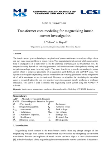
2[18]. Various circuit level techniques have employed PG toturnoff the idle circuits by creating a high impedance path toground [19] [20]–[22]. However, not much research has beendone to design a reliable PGS for GPGPUs considering theunique inrush current and voltage noise challenges. PGS canbe employed for memory units, such as register files and caches,but the contents will be lost due to power gating the storagestructure. They must be stored safely in an active memory andtransferred back to the registers and caches, which involvessignificant overheads. To avoid this, the voltage level of thesememory elements are simply lowered to drowsy states to savepower and retain states which is explained in section IV.Due to large performance overhead of memory/storage,where the contents of the state-retentive memory structures islost when power-gated [23], it is under-volted to a low leakagestate-retentive drowsy voltage [20]–[22]. In drowsy mode, theinformation in the SRAM cells are preserved but it is nonfunctional for read and write accesses.The prior works assume that the transition time between supply voltage and drowsy voltage is negligible (1-2 cc) [20], [22].According to our results from simulation of the shared memoryand register file, we observe that these voltage transition timesare non-negligible and they indeed affect the BET adverselysimilar to the power gating [24].There has been some prior works in the PGS design [19],[25], [26], however, our work is the first one to consider theeffect of inrush current on the PG switch design in GPUs to thebest of our knowledge. An always powered-on buffer is usedto generate the sleep signal, thereby incurring large leakagecurrent in drowsy state [25]. Multiple sleep modes are enabledusing multiple reference voltages at the source of the sleeptransistor in [26], which is power consuming. To reduce theleakage power, multiple sleep modes with low-leakage switchare used in [19].This work makes three major contributions: (1) we analyzethe realistic BET of the GPU components through Hspice simulation. We show that these times vary considerably dependingon the size, complexity and technology of the components.(2) We explore the design of PG switch considering theBET and inrush current for GPGPUs. (3) We select optimumundervolting level for storage structures, taking into accountthe voltage transition time, switching energy and static powerat each level of voltage, as well as idleness length of storagestructure during application execution. We redesign a multimodal PGS considering the tolerable inrush current as well asreasonable BET.The rest of the paper is organized a follows. In section II, wemodel BET and inrush current from other circuit parameters. Insection III, we analyze the effect of BET and inrush current onPGS switch design. In section IV, we estimate the optimumunder-volting level considering idleness length for storagestructures. We evaluate our design in GPGPU-Sim for leakagepower-savings in Register file, SP-Int and SP-Float units inSection V. And finally, conclusion and remarks are provided insection VI.II. P OWER G ATING A NALYSISFirst, we explore opportunities of reducing the leakage/staticpower in each and every stage of the pipeline. Static powerconsumption of the GPU components are extracted usingGPUWattch for GPU GTX 480 [27]. The Static power breakdown is shown in Table I. Execution units (including FPU andSFU) and the storage structures (like Register Files and SharedMemory) consume 21% and 46% of the total Streaming Multiprocessor (SM) static power respectively.As shown in the Fig. 1, PG switch is placed betweenpower supply and the target circuit. Note that transition timesencountered during the switch off and on operations, determinewhether or not, energy is saved during the PG operation. So,BET, which is defined as the minimum time that the PG switchmust be disabled to save energy, is the key point which isdiscussed in the following.A. Break-Even Time Estimation MethodBET is defined as the minimum time period which the targetcircuit should sleep in-order to save energy. The BET of theGPU components is estimated using Hspice simulation of thelumped RC model of the target component as shown in Fig. 1.In Fig. 1(a), CCKT and RCKT represent equivalent capacitanceand resistance of the GPU components respectively. Thesevalues are extracted by reverse engineering the GPUWattch.As shown in Fig. 1, when the PG switch is ON, the capacitorCCKT charges up through the PG switch that is representedby RP G (Fig. 1b). The current through PG switch, RCKT andCCKT are i1 , i2 and i3 respectively and can be represented bythe following equations:TABLE I: Static power breakdown of different components [27]GPU Pipeline UnitsStatic Power (%)Floating Point Unit17Cache3Special Function Unit4Shared Memory14Register File32 Instruction Decoder 9Instruction Fetch Unit 5Other16
TIInRushVDDPMax(VDD)PGSVirtualVDDEswitchingRCKT0 t1 t2(a) Lumped RC modelof a component withPG switch(b) ComponentWake-upOFF- ON(c) ComponentSleepON- OFFt4t3t5Fig. 2: Circuit block state transition during power gatingintervalFig. 1: Lumped RC model of a GPGPU componentthe impact of redesigned PGS for different application. βtRP G RCKTVDDi2 (t) (1 e CCKT ), β (1)RP G RCKTRP G RCKTVDD C βti3 (t) (e CKT )RP G(2)The time constant (τcharging ) for charging the capacitor is. Where β is measured according to Eq. 1As shown in Fig. 1(c), when the circuit block is idle, a”sleep” signal is applied to the PGS input signal so that thevirtual VDD is set to ’Zero’; and subsequently the target circuitis turned off (sleep mode). When the PG switch is OFF, thetarget component is put to sleep mode by discharging the CCKTthrough RCKT . The time constant for discharging the capacitoris τdischarging CCKT RCKT . Alternatively, while wakingup the target circuit, virtual VDD is set to VDD . Waking up thepower gated component, incurs the energy overhead during thetransition time from sleep to active mode.Fig. 2 shows the energy consumption of the circuit blockduring the PG interval. At tbreakeven , Esaved Eoverhead ; andthe values of Esaved and Eoverhead are obtained from equations3 and 4 respectively, where Pmax is the static power of targetcircuit at the supply voltage. Moreover, tdetect t1 is the timetaken by the control circuit to make a decision to power gatethe target circuit; Finally, tf all t3 t2 is the transition timeto turn-off and trise t5 t4 is the transition time to wake-upthe target circuit [28]. Eswitching is a function of Pmax , tdetect ,tf all and trise .CCKTβEsaved Pmax tbreakevenEoverhead Eswitching f (Pmax , tdetect , tf all , trise )tbreakevenEswitching PmaxB. Inrush CurrentInrush current is the high instantaneous current drawn bythe electrical circuit when powered on. When the circuit isswitched on from the power gated state, the capacitor acts as aVDDshort circuit, i1 i3 Rand i2 0 as shown in Fig. 1(b).PGAs of now, we define the power gated and active componentsas downstream and upstream components. The PGS switchensures to wake up the downstream component without disrupting the components functioning on the upstream domain.When the power gated component is abruptly waked-up, currentdraws from the upstream side to the downstream side. If alow-resistance power gate switch is used between the upstreamand downstream components, charge sharing occurs in lessthan 1 nsec and there is not sufficient time to charge thedownstream side from the external PDN [18]. This is because,the package inductance is high impedance and it blocks thecurrent from the outside for a short period of time. And thecharge in the components which share the same power isimmediately shared with downstream components. Assuminghalf of the SP units within the SM are active and half ofthem are power gated. when the power gated components wakeup, the equivalent capacitance of upstream and downstreamis same; Cactive Cpg . So, the voltage drops in the activecomponents in upstream domain. According to equations 7,the upstream domain voltage abruptly cut is half.(4)Vdda (5)Using Hspice, switching energy, wake-up time, fall time,and static power of the GPU components at a given voltage ismeasured using 45nm technology which is discussed in SectionIII. We use 45nm technology because GPGPU-Sim simulatorwhich is based on 45nm technology, will be used to estimate(6)Q Cup Vdd(3)QCup Cdown Cup VddbCup Cdown Vddb CupCup Cdown Vddb2(7)As illustrated in Equation 8, Iinrush is the amount of inrushcurrent due to the capacitance Cload and dV is the changein voltage during ramp up and dt is the rise time of theinput voltage signal during ramp up. If the inrush currentis not addressed, then it might lead to damages to circuitcomponents. As the current exceeds current handling capacity
4of the components, causes voltage drops and the circuit willfall out of regulation resulting in the system entering a faultystate. Hence, PG switch must be designed to withstand the highinrush current and control the voltage noise on the adjacentcircuit blocks which share the same power lane.Iinrush Cload dV /dT(8)Inrush current is inversely proportional to the wake-up timeof the component. So, in order to reduce the inrush current,the wake-up time of the power gated component/s need to beincreased which degrades the performance. So, there is a tradeoff between amount of inrush current and BET. We addressboth BET and inrush current in redesigning the PG switch inSection III.III. GPGPU P OWER G ATING S WITCH D ESIGNAs discussed earlier, we power gate the logics and undervoltthe storage structures. Several researches have designed PGSor voltage regulator without considering their impact on theBET and inrush current [29], [30]. Inrush current plays animportant role in GPUs because of higher number of corewhich can be power gated or activated at the same time due tobarrier synchronization. We simulate the impact of widely usedPGS on switching energy, wake-up time, and inrush currentconsidering the GPGPU components [19]. Then we relax itsdrawbacks by addressing these issues with redesigning the PGSwith considering the GPGPU limitations.The designed PGS can power gate the logics or make thestorage subsystems drowsy based on the input control signals.It can operates in active, sleep, and drowsy modes. Differentlevels of voltages can be generated and applied at the targetcircuit. If we use PGS, as footer cell, we should use NMOStransistor between circuit block and ground. NMOS has higherleakage current in comparison to PMOS. So, the sleep modecan not be maintained while we are using the PGS as the footercell. So, we use PMOS transistor in PGS as the header cell.As shown in Fig. 3, if SLEEP 0, regardless of the valueof the DROWSY signal, the MS1 and MS transistors are ONwhich generates Vdd at virtual VDD and the logic circuit willbe in active mode. When SLEEP 1, and DROWSY 0, thecircuit block starts to discharge through ground since it’s notconnected to VDD. Finally, when SLEEP 1, and DROWSY 1, the output of the sleep inverter will be drowsy voltage.There will be a negative feedback loop which generates virtualVDD at VVDD. The amount virtual VDD is depending on thetransistor width of MD1 and MS2.Fig. 3: Power Gating Switch Design [29]Correct sizing of different transistors in the PGS has directimpacts including logic gate switching speeds in the activemode, leakage currents in sleep, and drowsy modes, wake uplatency, and area overhead. For instance, as shown in Fig. 3,larger MS size results in higher active mode switching speedsbut also increases sleep and drowsy leakage currents in activemode. In previous researches, they have not investigated therelation of PGS and BET.We redesign the PGS to consider the inrush current as well asBET of the GPGPU components. By modeling the target circuitwith lumped RC model of the circuit, we find the rise/fall times,switching energy and as a result, the BET of the target circuit.To extract these parameters for the GPU main components,the equivalent resistance and capacitance of target componentssuch as register file bank, integer unit, floating point units, andetc, are measured according to Section III-A. Then, as shownin Fig. 1, we construct the PDN model of each component andestimate the rise/fall times, switching energy and inrush currentof the GPU components.A. Equivalent Capacitance and ResistanceThe PDN model of each component is created using capacitance (C) and resistance (R) of the component obtainedusing McPAT simulator, as in Eq. 9 and 11 respectively, wherePswitching is the dynamic switching power. Vdd is the supplyvoltage which is 1V, and f is the frequency considered 750MHz in GTX 480. Ishort circuit is the short-circuit currentand occurs when PMOS and NMOS devices become on simultaneously ON and Ipeak is the maximum value of the shortcircuit current. In Eq. 11, Ipeak is derived asPswitching /Vdd when the activity factor (α) is 1. Short-circuitpower ( Pshort circuit Vdd * Ishort circuit ) is modelled inEq. 10 and is the power consumed when both pull-up and pulldown devices are partially on for a small finite amount of time[31].
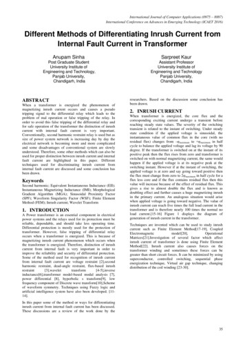
5Pswitching α CL Vdd Vdd fPshort circuit Vdd Ipeak rise f all f2Ishort circuit 5 Ipeak R Csc f(9)432101234Time (X) in Log nano secFig. 4: The impedance of sleep transistor during the wake-uptime using two different widthswell as the wake-up time that are key factors in the BET asillustrated in equation 5.(11)C. Optimizing the BETPrior researches assumed a BET of 14 cycles irrespective ofthe underlying circuit [28] [16]. The rise/fall times of differentcomponents are extracted using 45 nm technology. In our simulation, channel width and length of the transistor are assumed3 uM and 1.5 uM respectively according to [19]. The rise/falltimes for floating point, integer, and instruction fetch units areextracted according to lumped RC model while the rise and falltime of Register File, and Shared Memory are extracted usingHspice simulations. According to the simulation results whichare discussed in the following section, rise time of the circuitblocks does not follow the analytical model anymore and showsan aggressive increment. There is a huge difference betweenanalytical and measurement results with and without using thePGS. Previous researches have not considered the effect of PGSon the BET of the component. For simple components withlower capacitance and resistance, the performance overheadof switch is negligible. But with increasing the capacitanceand resistance of the component, the switch transistor playsan important role in BET of the component.Using Hspice, we also find the peak power (Ppeak ) andswitching energy(Eswitch ) which is shown in Table II. Theswitching energy divided by the peak power adds tens of cyclesto the BET of the GPU components as per equation 5. Weaim to optimize the impact of PGS on the switching energy asTABLE II: Peak Power and Switching Energy With and Without optimizing the PG switchNo OptimizationPpeak (uW)Eswitch 2.1414.55Cumulative Width 3000uM(10)B. Break-Even Time AnalysisGPU ComponentReg File BankShared MemFPUInteger UnitInstruction FetchImpedance of Sleep Transistor (log 10 Ohm)Width 3uMBy solving the mentioned equations, we extract the R andC values for the GPU pipeline components including registerfile bank, shared memory, floating point unit, integer unit, andinstruction fetch unit. C and R values corresponded for storagestructures are extracted at each bank level. This is because eachbank can be power gated separately since they do not share thepower lines and we can have fine granularity power gating forregister file.Optimized PGSPpeak (uW) Eswitch (pJ)150.01120.01180.06120.02140.003As illustrated in Table III, with current PGS design with theoriginal transistor widths, the BET is a very large number. Thisis because, PG switch uses a transistor with small channel widthwhich is considered as high resistive transistor and it adds tothe equivalent resistance of charging path that results in lesscurrent or higher wake-up time.The equivalent impedance of the PG switch varies during thedifferent operational modes of the transistor [32]. The operationof a MOSFET can be separated into three different modes,depending on the voltages at the terminals (Vgate , Vsource andVdrain ). There are three operational modes: cutoff, triode, andsaturation mode. [32] simplifies the transistor as an impedancewhich varies at different operational modes. As shown in Fig.3, during the wake-up time or charging period, MS1 and MStransistors experience different impedance at saturation andtriode mode.1) Impedance Analysis of the Sleep Transistor Switch: UsingHspice, we measure impedance of the sleep transistor duringthe wake-up time. To measure this value, we model the GPUcomponent with a lumped RC model as illustrated in Fig. 1. Fig.4 shows the impedance of MS transistor during the wake-uptime. Fig. 4 shows the results in logarithmic scale. It’s obviousthat, the impedance of the transistor decreases aggressively withincreasing the channel width of MS transistor. To simplify thePG sleep transistor and extract the main factors that affectthe impedance, PG switch is modeled as a resistor with animpedance that is given in Eq. 12 [32]. Where kn and WL arethe process-trans-conductance and width to length ratio of thesleep transistor, respectively. According to Eq. 12, changing thetransistor width changes the impedance of the switch transistor.R 1kn ( WL)(VGS Vthn )(12)
6FPUALUIFLog10 (Inrush Current ( A))432100.481.482.483.48Log10 (Switch TransistorWidth ( M))Fig. 5: Inrush current in presence of different switch transistorwidthsTo reduce the wake-up time and as a result BET, sleeptransistor width is increased according to Eq. 12. Using Hspice,first, we measure the effect of width on the BET. By increasingwidth of the switch transistor channel, the impedance of thethe switch transistor is reduced in different operational modeswhich leads to less impedance during the charging period andas a result lower BET. In this case, we need to use a switchtransistor with a large width that is not practical.Instead of using one transistor with large width, we areusing several switch transistors which are activated sequentially.When these transistors activate, they have the lowest equivalentresistance and draw maximum amount of current. So, we usefew number of transistors with small channel widths which giveus the same BET equal to the estimated larger transistor. Withoptimizing the channel width of transistors, we also decreasedthe switching energy of each component. Table II shows theswitching energy and peak power of the GPU components.Previously, with the default transistor width, the switchingenergy was playing an important factor in the BET of thecomponents [28]. But, as shown in Table II, the switchingenergy is decreased sensibly and as a result it’s contributionin the BET is not sensible anymore.Table III shows the rise and fall time of the GPU pipelinemain components with none optimized PGS that uses thedefault transistor width and optimized PGS which employsenough number of small transistors to drive the sufficientFig. 6: Modifying the PGS to relax the inrush current withoutchanging the BETcurrent into the circuit blocks in a reasonable time. As shownin the table, the rise and fall time of the circuit blocks aresensibly decreased so that power gating and undervolting canbe applied now.D. Relaxing The Inrush CurrentFig. 5 shows the inrush current for GPU components suchas Floating Point, Instruction Fetch (IF), and Integer Unit. Theamount of inrush current increases sensibly with employingthe cumulative larger transistor widths. As shown in Fig. 6, weaddress this problem by adding a transistor ”MI” with smallwidth in parallel with sleep transistor. At time of wake-up, MItransistor wakes up earlier than MS1/MS2 transistor since thesleep signal is directly connected to the MI transistor but takesmore time to change the GS signal to 0 volt, because, first,transistors inside the sleep inverter should be activated whichincurs a delay to change of input signal of MS1/MS2. So, therewould be a delay between activation of MS1/MS2 transistorand MI transistor. MI transistor has small width and as a resultlarger impedance according to Eq. 12. MI transistor leads to lessinrush current, because, by the time MS transistor is activated,the circuit block charge is not 0V anymore and hence theequivalent capacitor of the component does not perform as shortcircuit.The amount of inrush current depends on the transistor widthof MI transistor. Smaller width leads to lesser inrush current.With default transistor width, the inrush current does not changedue to resizing the original design.IV. U NDERVOLTING THE S TORAGE S TRUCTURESTABLE III: Rise and fall time of the GPU components inpresence of none optimized PGS and optimized PGSGPU ComponentRegister File bankShared MemoryFloating Point UnitInteger UnitInstruction Fetch UnitNone OptimizedRise Fall time (ns)6948457.49825OptimizedRise Fall time (ns)151218124The optimum level of undervolting is decided by considering the static power at each level, transition latency andswitching energy between different power modes which isextracted through Hspice simulation. Table IV, shows staticpower (Pstatic ), switching energy (Eswitching ), transition latency (Twake up ) from each voltage level till the nominalvoltage (1 V) and BET. BET time corresponding to each voltage
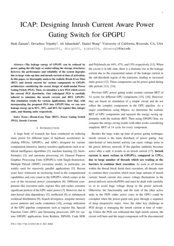
7806040200(a) Register Energy Saving(b) Integer Energy SavingWarped Merge SortThreadfenceRedBtreeBack propHeartWallHotspotPath finderMatrix mul40ICAPFP Static Energy Saving (%)60Warped GatesAverageInteger Static Energy Saving (%)10080BFSVectorAddMerge SortThreadfenceRedBtreeBack propHeartWallHotspotPath finderMatrix mulReg Static Energy Saving (%)ICAPBFSVectorAddMerge SortThreadfenceRedBtreeBack propHeartWallHotspotPath finderMatrix mulWarped Register File100(c) Floating Point Energy SavingFig. 7: Leakage energy savings for registers, integer and floating point unit with oracle knowledgeis calculated using Equation 5. Based on the idleness length ofthe register file bank, the optimum level of voltage is selected.According to our observations and for simplicity of the PGSdesign, it is sufficient to use only 3 voltages called ”shallowsleep 0.7 V”, ”deep sleep 0.3 V”, and ”active state 1 V”.Hence, storage structures are switched to a state-retentive lowpower mode to have maximum energy savings without compromising the performance. In our approach, GPGPU pipelinestorage structures are connected to the supply voltage (Vdd ) railvia the multi-modal power gating switch in Figure 6.The multi-modal PGS shown in Figure 6 is used to generatedifferent levels of voltage across the memory subsystem. Asshown in Fig. 6, PGS employs two inverters, which, onlyone of them is active at a time. They have different channelwidths, so that they can generate two levels of voltage atvirtual VDD . The channel widths are extracted through Hspicesimulations. Finding the optimum level of voltage depends onthe performance overhead of transition between different lowpower states. In low power mode, storage structure should bestate-retentive, such that during the low power mode, memorycontents are preserved. The conservative data-retention voltageused is 0.3V for the register file file bank [20]. PGS illustratedin Figure 6 is able to generate Vdd , ’0’, ’shallow sleep 0.7’, and ’deep sleep 0.3’. We can generate more number ofTABLE IV: Determining optimum undervolting level for register fileVoltage0.30.40.50.60.70.80.9Pstatic (uW )1.772.022.42.753.23.63.97Eswitch (nJ)27.828.3329.8731.0131.3428.6125.93Twake up (ns)12.8311.6110.399.177.926.543.78BET (nS)15.7814.0512.4511.39.727.926.54voltage levels with adding MS transistor with different channelwidth.V. E VALUATIONWe have implemented Inrush Current Aware Power GatingSwitch (ICAP) in GPGPU-Sim v3.2.1 [11], based on an NvidiaFermi-like GPU configuration with 15 SMs. Each SM has a128 KB register file organized into four banks, and 2 SPs.We enabled PTXPlus for all of our evaluations. Each SM alsohas two warp schedulers configured to use a two-level warpscheduler. In all experiments, we use 10 benchmarks selectedfrom Rodinia, Nvidia Cuda-SDK, ISPASS, and Polybenchbenchmark suites. The benchmarks cover a range of behaviorsand instruction mixes (load store/integer/floating point). TheStreaming Processor(SP) comprises of the integer and floatingpoint pipeline which do not support concurrent execution.So, one unit is likely to remain idle when the other unit isactive. Each Integer and Floating point unit is connected to amulti-modal switch to switch between different voltage levelsdepending on the predicted idle period length.Fig. 7, shows the comparison of maximum Leakage energysavings of the Inrush Current Aware Power Gating Switch(ICAP) with the state-of-art leakage energy saving techniquesfor GPU register file, integer, and FP unit [20].Since the average register reuse distance is in order of 100clock cycles, the increased wake-up latency from drowsy toON state results in marginal differences in the leakage energysavings. However, in case of the SP unit, frequency of theshorted idle period (less th
portunity with the realistic BET. Then using GPGPU-Sim, we compare the energy saving results with other works considering simplistic BET of 14 cycle for every component. Besides the large wake up time of power gating technique, inrush current is the main drawback of power gating. Any inter-kernel or intra-kernel activity can cause voltage noise in