Transcription
STORMWATER BEST MANAGEMENTPRACTICE SIMPLIFIED SIZING TOOLKitsap CountyPrepared forKitsap CountyPublic Works Department614 Division Street, MS-26Port Orchard, Washington 98366-4699Prepared byHerrera Environmental Consultants2200 Sixth Avenue, Suite 1100Seattle, Washington 98121Telephone: 206.441.9080March 10, 2010
Note:Some pages in this document have been purposefully skipped or blank pages inserted so that thisdocument will copy correctly when duplexed.
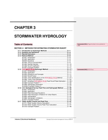
ContentsIntroduction . 1Pre-designed Stormwater BMPs . 1Low Impact Development BMPs . 1Bioretention . 4Permeable Pavement . 5Trees . 7Partial Dispersion . 8Vegetated Roofs . 9Traditional Infiltration BMPs . 9Rock Trench . 9Gravelless Chamber . 9Detention BMPs. 10Infiltration Rates . 10Stormwater Management Standards . 11Modeling Methods . 12Sizing Factors for Infiltration Facilities . 12Sizing Equations for Detention Pipe . 14BMP Flow Control Credits . 20Retained and New Trees . 20Downspout or Sheet Flow Dispersion . 21Vegetated Roof . 21Permeable Pavement Surfaces (2 percent or less subgrade slope) . 22Permeable Pavement Surfaces (2 to 5 percent subgrade slope) . 23County-Wide BMP Sizing Tool. 23Sizing Equations . 23Flow Control Credits . 27Conclusions . 31References . 33Attachment AAttachment BAttachment CAttachment DAttachment ESeattle Public Utilities Draft Bioretention Soil Specification (January 2010)Rock Trench DesignGravelless Chamber DesignBMP Modeling Methods, Assumptions and Inputs TableBMP Sizing Plots by Precipitation Depthjr 09-04247-000 stormwater bmp simplified sizing tool.doci
TablesTable 1.BMPs included in the simplified sizing tool. . 3Table 2.Infiltration rates recommended by the Department of Ecology. 11Table 3.BMP sizing factors by mean annual precipitation. . 15Table 4.Sizing equations for detention pipe (42-inch diameter) by mean annualprecipitation. . 20Table 5.Flow control credits for retained trees. . 21Table 6.BMP flow control performance by mean annual precipitation. . 22Table 7.Permeable pavement surface aggregate storage reservoir depth by meanannual precipitation (for installations up to 2 percent slope). 23Table 8.Regression factors for BMP sizing in Kitsap County. . 28Table 9.Flow control credits for BMPs in Kitsap County. . 29Table 10. Permeable pavement surface aggregate storage reservoir depth for KitsapCounty. . 29FiguresFigure 1. Average annual precipitation depths in Kitsap County (courtesy of KitsapPublic Utility District). 2Figure 2. Bioretention facility (bottom area) sized for flow control as a function ofcontributing impervious area (mean annual precipitation of 52 inches). 13Figure 3. Permeable pavement facility sized for flow control as a function ofcontributing impervious area (mean annual precipitation of 52 inches). 13Figure 4. Detention pipe sized for flow control as a function of contributing imperviousarea (mean annual precipitation of 52, 44, 36, and 32 inches). . 19Figure 5. Bioretention flow control sizing factors for Kitsap County as a function ofmean annual precipitation. . 24Figure 6. Bioretention water quality sizing factors for Kitsap County as a function ofmean annual precipitation. . 24Figure 7. Permeable pavement facility flow control sizing factors for Kitsap County as afunction of mean annual precipitation. . 25Figure 8. Rock trench flow control sizing factors for Kitsap County as a function ofmean annual precipitation. . 26jr 09-04247-000 stormwater bmp simplified sizing tool.docii
Figure 9. Gravelless chamber flow control sizing factors for Kitsap County as afunction of mean annual precipitation. . 26Figure 10. Permeable pavement surface aggregate depth sizing factors for Kitsap Countyas a function of mean annual precipitation. . 30Figure 11. Kitsap County BMP Sizing Calculator. . 32jr 09-04247-000 stormwater bmp simplified sizing tool.dociii
Stormwater Best Management Practice Simplified Sizing Tool—Kitsap CountyIntroductionHerrera Environmental Consultants was retained by the Kitsap County Public Works Departmentand the Kitsap Home Builders Foundation to develop a simplified sizing tool for low impactdevelopment (LID), infiltration, and detention best management practice (BMP) design in KitsapCounty (County). Precipitation depths and rainfall patterns vary widely across the County withmean annual precipitation ranging from 26 inches in the north to 68 inches in the southwesterncorner (Figure 1). The goal of this study was to develop simple mathematical relationships toallow sizing of pre-designed BMPs as a function of contributing impervious area, site infiltrationrates, and mean annual precipitation. To develop the simplified sizing tool, benefits for selectedBMPs were quantified either as flow control credits (runoff reduction credits) or sizing equations(relating the facility size to the impervious area mitigated). This tool allows the designer to sizeBMPs without extensive calculations or continuous modeling, and can streamline agency reviewof design submittals by providing “rule of thumb” sizing equations. By providing pre-designedand pre-sized LID BMPs, this tool helps reduce barriers to LID implementation across KitsapCounty.This report presents a description of the stormwater BMPs included, the infiltration ratesevaluated, the stormwater management standards used, the modeling and regression analysismethods employed, and the resulting County-wide BMP sizing equations.Pre-designed Stormwater BMPsThe sizing tool was developed for selected LID, infiltration, and detention BMPs (Table 1). Touse the sizing tool, the BMPs must be designed per the design requirements listed in this section.Additional requirements (including infiltration rate testing methods, infiltration rate correctionfactors, setbacks, and vertical separation from the bottom of the facility to the underlying watertable) are presented in the Washington State Department of Ecology (Ecology) StormwaterManagement Manual for Western Washington (Ecology 2005), the Kitsap County StormwaterManagement Design Manual (Kitsap County 1997), and the Kitsap County Low ImpactDevelopment (LID) Guidance Manual (Kitsap Home Builders Foundation 2009). Supplementaldesign resources for LID BMPs (e.g., recommended construction specifications) are available inthe City of Seattle Stormwater Flow Control and Water Quality Treatment TechnicalRequirements Manual (Seattle 2009). Additional state-of-the-practice design guidance for LIDBMPs will be forthcoming in 2011 in the updated LID design manual being prepared byWashington State University Cooperative Extension for the Puget Sound Partnership.Low Impact Development BMPsSizing factors or flow control credits were developed for a suite of LID BMPs: bioretention,permeable pavement, trees, partial dispersion, and vegetated roofs. BMP descriptions and designrequirements are presented below.jr/09-04247-000 stormwater bmp simplified sizing tool.docMarch 10, 20101Herrera Environmental Consultants
Stormwater Best Management Practice Simplified Sizing Tool—Kitsap CountyFigure 1. Average annual precipitation depths in Kitsap County (courtesy of KitsapPublic Utility District).jrHerrera Environmental Consultants2/09-04247-000 stormwater bmp simplified sizing tool.docMarch 10, 2010
Stormwater Best Management Practice Simplified Sizing Tool—Kitsap CountyTable 1.BMPs included in the simplified sizing tool.Design Infiltration Rate(inch per hour)BMP Sizing ToolBMPDesign ConfigurationFlow ControlTreatment0.130.250.51.02.0XLID Runoff Reduction MethodsRetaining TreeEvergreen & DeciduousFlow CreditNAPlanting New TreeEvergreen & DeciduousFlow CreditNAPartial DispersionDownspout & Sheet FlowFlow CreditNAVegetated Roof4- and 8-inch Growth Media DepthFlow CreditNAPermeable Pavement Surface2-5% SlopeCredit & Factor—XXPermeable Pavement Surface 2% SlopeCredit & Factor—XXLID FacilitiesBioretention2-, 6- & 10-inch Ponding DepthSizing FactorSizing FactorXXXPermeable Pavement Facility6-inch Storage Reservoir DepthSizing Factor—XXXRock TrenchSizing Factor—XXXXGravelless ChamberSizing Factor—XXXXSizing EquationNATraditional Infiltration FacilitiesDetention FacilitiesDetention PipeX—NA%jr42-inch Pipe, 0.5-inch Orificeevaluated as part of this studynot evaluated as part of this studynot applicablepercent/09-04247-000 stormwater bmp simplified sizing tool.docMarch 10, 20103Herrera Environmental Consultants
Stormwater Best Management Practice Simplified Sizing Tool—Kitsap CountyBioretentionBioretention facilities, also known as rain gardens, are shallow depressions with a designed soilmix and plants adapted to the local climate and soil moisture conditions. The healthy soilstructure and vegetation promote infiltration, water storage, and slow release of stormwater flowsto more closely mimic natural conditions. When used for flow control, bioretention facilitiesmust not have an underdrain to intercept infiltrated runoff or an impermeable liner impedinginfiltration to underlying soil. Three design variations were evaluated: a 2-inch, 6-inch, and10-inch ponding depth.In order for the pre-sizing results presented in this report to be applicable, the followingbioretention facility design requirements must be met: The drainage area contributing runoff to an individual bioretention facilityshall be no larger than 5,000 square feet of pollution generatingimpervious surface, 10,000 square feet of impervious surface, or 3/4 acreof lawn and landscape 1 . Bioretention bottom area shall be sized using the sizing tool. Top area (total facility footprint) will be larger than the bottom area andcan be calculated as a function of the bottom area, the side slopes, and thetotal facility depth (e.g., ponding and freeboard depth). Bottom area shall be flat (0 percent slope). Side slopes within the ponded area shall be no steeper than 3H(horizontal):1V (vertical). Imported bioretention soil per City of Seattle specifications shall be used.This draft specification is included as Attachment A. Future updates to thisspecification will be posted on the SPU green stormwater infrastructurewebsite (http://www.seattle.gov/util/greeninfrastructure). This soil mixmeets the Washington State Department of Ecology (Ecology) treatmentsoil requirements, has a design infiltration rate of 3.0 inches per hour 2 , andhas 40 percent porosity. Because imported bioretention soil is used, the design infiltration rate ofthe underlying native soil does not require a correction factor (i.e., thedesign, or “long-term” infiltration rate is the same as the “initial”infiltration rate).1The area limitation is to ensure that bioretention facilities are small-scale and distributed. Also, the assumedinfiltration rate correction factor applied to City of Seattle standard bioretention soil mixes is based on a contributingarea that does not exceed 5,000 square feet of impervious surface.2Modeling was performed using a 2.5 inch per hour design infiltration rate for the bioretention soil mix. Therefore,the sizing equations will result in conservative facility sizes.jr /09-04247-000 stormwater bmp simplified sizing tool.docHerrera Environmental Consultants4March 10, 2010
Stormwater Best Management Practice Simplified Sizing Tool—Kitsap County Bioretention soil depth shall be a minimum of 12 inches for flow control,and minimum of 18 inches for water quality treatment. No underdrain or impermeable layer shall be used if designed for flowcontrol. Minimum ponding depth shall be as specified (2, 6, or 10 inches).In addition to the requirements listed above, a maximum surface pool drawdown time of24 hours is recommended, and often required. Allowing the soil to dry out periodically isnecessary to restore hydraulic capacity of the system for subsequent storms, maintain infiltrationrates, maintain adequate soil oxygen levels for healthy soil biota and vegetation, and provideproper soil conditions for treatment. While bioretention facilities with 10 inches of ponding andan infiltration rate of 0.25 inch per hour were sized as part of this study, the surface pooldrawdown time exceeds 24 hours, so this design configuration may not be permitted.Permeable PavementPermeable pavement is a paving system that allows rainfall to percolate into an underlyingaggregate storage reservoir, where stormwater is stored and infiltrated to underlying soil. Apermeable pavement system consists of a pervious wearing course (e.g., porous asphalt concrete,porous cement concrete, paver blocks, or open-celled paving grids) and an aggregate subbasecourse installed over native soil. Two categories of permeable pavement systems were includedin this study: permeable pavement surfaces and permeable pavement facilities.A permeable pavement surface is designed to manage only the water that falls upon it and is notintended to take significant stormwater run-on from other areas.A permeable pavement facility typically has a thicker aggregate storage reservoir than a surfaceand may be designed to receive stormwater run-on from other areas. For slopes greater than2 percent, the subbase must be designed to create subsurface ponding to detain subsurface flowand increase infiltration. Ponding may be accommodated using design features such as terracingberms (check dams) or intermittent infiltration trenches. When the subsurface soil slope is lessthan 2 percent, at least one low permeability check dam should be installed at the downslope endof the aggregate storage reservoir to contain water in the facility. Additional design features maybe required, including an overflow to keep the top section of the pavement dewatered (to addressfreeze/thaw concerns).In order for the pre-sizing results presented in this report to be applicable, the followingpermeable pavement facility design requirements must be met:jr Pervious pavement area shall be sized using the sizing tool. The infiltration rate used to determine the sizing equation shall be thedesign, or “long-term”, rate and must be calculated using correctionfactors (safety factors) per the Ecology Stormwater Management Manual/09-04247-000 stormwater bmp simplified sizing tool.docMarch 10, 20105Herrera Environmental Consultants
Stormwater Best Management Practice Simplified Sizing Tool—Kitsap Countyfor Western Washington (Ecology Manual). Based on conversationsbetween Kitsap County and Ecology staff, the following minimumcorrection factors are recommended:Facility not receiving stormwater run-on: correction factor of 2Facility receiving stormwater run-on from an area less than twicethat of the facility: correction factor of 2Facility receiving stormwater run-on from an area larger than twicethat of the facility: correction factor of 4 Average subsurface ponding depth within the aggregate storage reservoirshall be a minimum of 6 inches. For areas where the subgrade has a slope of 2 percent or more, the averagesubsurface ponding depth shall be controlled to achieve the 6 inchminimum ponding depth. Ponding may be accommodated using designfeatures such as terracing berms (e.g., check dams). For areas where the subgrade has a slope of less than 2 percent, at leastone low permeability check dam should be installed at the downslope endof the aggregate storage reservoir to contain water in the facility. Aggregate shall have a minimum void volume of 20 percent Slope of the subgrade underlying the pervious pavement shall be less than5 percent. No underdrain or impermeable layer shall be used. The sizing relationship is not applicable for an infiltration rate of0.25 inches per hour when the mean annual precipitation exceeds37 inches.In order for the pre-sizing results presented in this report to be applicable, the followingpermeable pavement surface design requirements must be met: Aggregate depth shall be sized using the sizing tool. For subgrade slopes greater than 2 percent the flow control standard is notachieved and the mitigated area shall be calculated using the flow controlcredit. The pavement surface shall not receive stormwater run-on from otherareas. Aggregate shall have a minimum void volume of 20 percent.jr /09-04247-000 stormwater bmp simplified sizing tool.docHerrera Environmental Consultants6March 10, 2010
Stormwater Best Management Practice Simplified Sizing Tool—Kitsap County Slope of the subgrade underlying the permeable pavement surface shall beless than 5 percent. No underdrain or impermeable layer shall be used.TreesTrees provide flow control via interception, transpiration, and increased infiltration. Additionalenvironmental benefits include improved air quality, carbon sequestration, reduced heat islandeffect, pollutant removal, and habitat preservation or formation. When implemented inaccordance with the criteria outlined below, retained and newly planted trees can viably becredited toward meeting flow control requirements. The degree of flow control provided by atree depends on the tree type (i.e., evergreen or deciduous), canopy area, and whether or not thetree canopy overhangs impervious surfaces.In order for the flow control credits presented in this report to be applicable, the followingrequirements must be met for both retained and newly planted trees: Trees shall be retained, maintained and protected on the site afterconstruction and for the life of the development or until any approvedredevelopment occurs in the future. Trees that are removed or die shall bereplaced with like species during the next planting season (typically infall). Trees shall be pruned according to industry standards. Tree credits are not applicable to trees in native vegetation areas used forflow dispersion or other flow control credit. Trees must be on the development site and within 20 feet of new and/orreplaced ground level impervious surfaces (e.g., driveway, patio, orparking lot). Distance from impervious surfaces is measured from the edgeof the surface to the center of the tree at ground level. Trees planted in planter boxes are not eligible for flow control credit. The total tree credit for retained and newly planted trees shall not exceed25 percent of impervious surface area requiring mitigation.Retained tree requirements include the following:jr Trees must be viable for long-term retention on the site (i.e., in goodhealth and compatible with proposed construction). Retained trees shall have a minimum 6 inches diameter at breast height(DBH). DBH is defined as the outside bark diameter at 4.5 feet above theground on the uphill side of a tree. For existing trees smaller than this, thenewly planted tree credit may be applied./09-04247-000 stormwater bmp simplified sizing tool.docMarch 10, 20107Herrera Environmental Consultants
Stormwater Best Management Practice Simplified Sizing Tool—Kitsap County The retained tree canopy area shall be measured at the time of permitapplication as the area within the tree drip line. A drip line is the lineencircling the base of a tree, which is delineated by a vertical lineextending from the outer limit of a tree's branch tips down to the ground.If trees are clustered, overlapping canopies are not double counted. The existing tree roots, trunk, and canopy shall be fenced and protectedduring construction activities to avoid damage to the tree.Newly planted tree requirements include the following: New deciduous trees shall be at least 1.5 inches in diameter measured6 inches above the ground. New evergreen trees shall be at least 4 feet tall. Approved tree species are listed in the City of Seattle Tree List availablevia link from the SPU GSI web re). Mature tree height, size, and rooting depth must be considered to ensurethat the tree location is appropriate given adjacent and above- and belowground infrastructure. To help ensure tree survival and canopy coverage, the minimum treespacing for newly planted trees shall accommodate mature tree spread (seeCity of Seattle Tree List). In no circumstance shall flow control credit begiven for new tree density exceeding 10 feet on center spacing. Provisions shall be made for supplemental irrigation during the first threegrowing seasons after installation to help ensure tree survival.Partial DispersionPartial dispersion of stormwater runoff attenuates peak flows by slowing entry of the runoff intothe conveyance system, allows for some infiltration, and provides some water quality benefits.Sheet flow dispersion is a simple BMP comprised of an impermeable surface that drains to astrip of vegetation in a non-concentrated form. Downspout dispersion BMPs are splashblocks orgravel-filled trenches that serve to spread concentrated flows over vegetated pervious areas.These partial dispersion techniques differ from Ecology’s full dispersion BMP which requirespreservation of at least 65 percent of the site in a forest of native condition and achieves full flowcontrol credit.To use the flow control credits for sheet flow or downspout dispersion presented in this report,the BMPs must be designed per the requirements (e.g., minimum vegetated flow paths) presentedin the Ecology Manual.jr /09-04247-000 stormwater bmp simplified sizing tool.docHerrera Environmental Consultants8March 10, 2010
Stormwater Best Management Practice Simplified Sizing Tool—Kitsap CountyVegetated RoofsVegetated roofs are areas of living vegetation installed on top of buildings to provide stormwaterflow control via attenuation, soil storage, and losses to interception, evaporation, andtranspiration. Vegetated roofs are also known as ecoroofs, green roofs, and roof gardens.A vegetated roof consists of a system in which several materials are layered to achieve thedesired vegetative cover and drainage characteristics. Design components vary depending on thevegetated roof type and site constraints, but typically include a waterproofing material, a rootbarrier, a drainage layer, a separation fabric, a growth medium (soil), and vegetation. Flowcontrol credits were developed for 4- and 8-inches of growth media depth. Establishing detaileddesign requirements for vegetated roofs is outside of the scope of this report.Traditional Infiltration BMPsSizing factors were developed for two traditional infiltration BMPs: rock trenches and gravellesschambers. BMP descriptions and design requirements are presented below.Rock TrenchThe rock trench BMP is based on guidance for downspout infiltration trench designs, presentedin the Ecology Manual (Ecology 2005). A typical trench design is shown in Attachment B. ThisBMP consists of an aggregate-filled trench where collected stormwater is temporarily stored andthen infiltrated into the underlying soil. The trench cross section is 24 inches wide and 18 incheshigh before overflow and the trench length was sized to meet Ecology’s flow controlrequirements (outlined in detail below).In order for the pre-sizing results presented in this report to be applicable, the following rocktrench facility design requirements must be met: Rock trench length shall be determined using the sizing tool. The infiltration rate used to determine the sizing equation shall be thedesign, or “long-term,” rate and must be calculated using correctionfactors per the Ecology Manual. Trench cross section shall be 24 inches wide by 18 inches high beforeoverflow. Trench aggregate shall have a minimum void volume of 30 percent.Gravelless ChamberThe gravelless chamber BMP is based on guidance presented in the Kitsap County StormwaterManagement Design Manual (Kitsap County 1997). A typical chamber design is shown injr/09-04247-000 stormwater bmp simplified sizing tool.docMarch 10, 20109Herrera Environmental Consultants
Stormwater Best Management Practice Simplified Sizing Tool—Kitsap CountyAttachment C. This BMP consists of a buried chamber where collected stormwater istemporarily stored and then infiltrated into underlying soil. Gravelless chambers create anunderground cavity that can provide a greater void volume than rock trenches and often require asmaller footprint. Per County requirements, the chamber must have a minimum void volume of2.6 cubic feet per linear foot and a minimum infiltrative surface of 2.8 square feet per linear foot.In order for the pre-sizing results presented in this report to be applicable, the followinggravelless chamber facility design requirements must be met: Chamber length shall be determined using the sizing tool. The infiltration rate used to determine the sizing equation shall be thedesign, or “long-term,” rate and must be calculated using correctionfactors per the Ecology Manual. Void (storage) volume provided by the chamber shall be at least 2.6 cubicfeet per linear foot. Infiltrative surface under chamber footprint shall be at least 2.8 square feetper linear foot.Detention BMPsSizing equations were developed for a 42-inch diameter detention pipe designed per Ecologyrequirements (Ecology 2005). In order for the pre-sizing results presented in this report to beapplicable, the following additional detention pipe design requirements must be met: Pipe length shall be determined using the sizing tool. Detention pipe shall be a minimum of 42-inches in diameter. The low flow orifice diameter shall be 0.5 inches with its invert elevationset at 6 inches above the bottom of the pipe. The overflow invert elevation shall be set no lower than 3 feet above theinvert of the low flow orifice (i.e., at the crown of the 42-inch diameterpipe).Infiltration RatesBMPs that infiltrate stormwater to underlying soil were sized for up to five design infiltrationrates: 0.13, 0.25, 0.5, 1.0 and/or 2.0 inches per hour. The rates used vary by BMP and arepresented in Table 1.The Department of Ecology offers the USDA Soil Textural Classification approach as onemethod to determine long-term infiltration rates for a given project. Tab
STORMWATER BEST MANAGEMENT PRACTICE SIMPLIFIED SIZING TOOL Kitsap County Prepared for Kitsap County Public Works Department 614 Division Street, MS-26 Port Orchard, Washington 98366-4699 Prepared by Herrera Environmental Consultants 2200 Sixth Avenue, Suite 1100 Seattle, Washington 98121 Telephone: 206.441.9080 March 10, 2010
