Transcription
rbulletin 99 — september 1999Concurrent Engineering Applied to SpaceMission Assessment and DesignM. Bandecchi & B. MeltonMission Control Systems Division, ESA Directorate for Technical and OperationalSupport, ESTEC, Noordwijk, The NetherlandsF. OngaroGeneral Studies Programme, ESA Directorate for Strategy, ParisIntroductionWithin the framework of its General StudiesProgramme (GSP), ESA performs a number ofpre-Phase-A assessment studies each year.The purpose of these studies is to assess thefeasibility of a new space mission from thetechnical, programmatic and economic pointsof view. This is normally achieved by producinga preliminary conceptual design of the missionand space system. The resulting study report isused as an input to the industrial Phase-Adesign studies.ESA performs pre-Phase-A assessment studies as part of thedefinition of future space missions. To evaluate the benefits of the‘concurrent engineering’ approach to these studies, an experimentaldesign facility was created in ESTEC and used to perform anassessment of the Italian Space Agency’s CESAR (Central EuropeanSatellite for Advance Research) mission. This article describes theapproach adopted and the experience gained during the study, anddraws preliminary conclusions on this new approach to spacemission assessment and design.Pre-Phase-A studies are normally performedin-house at ESTEC, by technical-supportspecialists using a classical approach, in whicheach specialist prepares a subsystem designrelatively independently from the others, usingstand-alone tools. Design iterations at systemlevel take place in meetings at intervals of a fewweeks. This method, which is still the one mostfrequently used, has obvious advantages, suchas the flexibility in the use of manpowerresources and the fact that it is a well-tried androutine process. On the other hand, it hasdrawbacks in that it favours a certain‘segregation’ in the subsystem preliminarydesign, reducing the opportunity to findinterdisciplinary solutions and to create systemawareness in the specialists. Furthermore, thetime required for performing studies using theclassical approach (6–9 months) may beincompatible with today’s drive towards ashorter time-span from mission concept tospacecraft flight (e.g. the SMART and Fleximissions).An alternative to the classical approach isoffered by ‘concurrent engineering’, whichprovides a more performant design method bytaking full advantage of modern informationtechnology. There are many definitions of themeaning of this term, but the following one bestdescribes the thinking behind the experimentdescribed in this article:‘Concurrent engineering is a systematicapproach to integrated product developmentthat emphasises the response to customerexpectations. It embodies team values of cooperation, trust and sharing in such a mannerthat decision making is by consensus, involvingall perspectives in parallel, from the beginningof the product life-cycle.’The concept is not new; in fact, it is alreadypractised in many industrial sectors throughoutthe product development cycle. There are alsoexamples in the space domain, such as thewell-known NASA/JPL Project Design Center,used for conceptual mission design. In ESA,the method has been studied and even alreadypartially applied in two mission-assessmentstudies (Euromoon and Venus Sample Return).These examples were not concerned with thesuitability of the method itself, being focussedmore on the actual mission under definitionrather than a re-usable infrastructure.The objectives of the current experiment were to:– create an experimental mission designenvironment (hereafter referred to as theConcurrent Design Facility, or CDF) in whichthe conceptual design of space missionscould be addressed in a more effective way
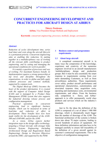
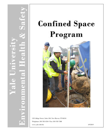
concurrent engineering– apply the practice of concurrent engineeringto a number of test cases to identify thepotential of such an approach in the variousphases of space-mission development– gather the information needed to evaluatethe resources required to create a permanentfacility available to all programmes.A first case study was provided by the CESARmission assessment, performed from Januaryto March 1999, which ESA had undertakenjointly with the Italian Space Agency (ASI), onbehalf of the Central European Initiative (CEI).The approachThe means to create the facility on anexperimental basis was simply to organise theexisting tools and human resources alreadyemployed for space-mission assessmentstudies in a more effective (i.e. concurrent) way.The concurrent-engineering approach is basedon five key elements:– a process– a multidisciplinary team– an integrated design model– a facility, and– a software infrastructure.The processThe conceptual model of the design process isshown in Figure 1, which highlights the fact thata space system has many interdependenciesbetween components. This implies that thedefinition and evolution of each component hasan impact on other components and that anychange will propagate through the system. Theearly assessment of the impact of changes isessential to ensure that the design processconverges on an optimised solution. Theconcurrent-engineering approach is intendedto provide the means to achieve this.The process starts with a few meetingsinvolving a restricted number of specialists(customer, team leader, system engineer) torefine and formalise the mission requirements,to define the constraints, to establish designdrivers, and to estimate the resources neededto achieve the study objectives.The design process is conducted in a numberof sessions in which all specialists mustparticipate. It is an iterative process thataddresses all aspects of the system design in aquick and complete fashion. The simultaneousparticipation of all of the specialists reducesFigure 1. Conceptual modelof the mission andspacecraft design process
rbulletin 99 — september 1999 bullthe risk of incorrect or conflicting designassumptions, as each major decision isdebated and agreed collectively. In this way thedesign progresses in parallel and allows thosedisciplines that were traditionally involved at alater stage of the process the opportunity toparticipate from the beginning, to correcttrends that might later invalidate the design.The customer is invited to participate in allsessions along with other specialists of his/herchoice (e.g. study scientist, project controller),so that they can contribute to the formulation ofthe study assumptions, answer questions fromthe team, and follow the evolution of thedesign. This includes the possibility to discussand correct in real time any orientation of thedesign not in line with their expectations.The first design session starts with thecustomer presenting the mission requirementsand constraints to the team. In subsequentsessions, each specialist presents theproposed option or solutions for his/her domain,highlighting/discussing the implications for theother domains. Out of this debate, a baseline isretained and the related values recorded in ashared database.One key factor is the ability to conduct aprocess that is not dependent on the pathfollowed. At any step, it must be possible totake advantage of alternative paths or use‘professional estimates’ to ensure that theprocess is not blocked by lack of data or lackof decisions.The teamA group of engineering specialists workingtogether in one room, using sophisticatedtools, are all essential elements but they are notsufficient to create a collaborative environment.On the contrary, it might become the placewhere conflicts are amplified. Above all else,the group of specialists must work as a team.A fundamental part of the concurrentengineering approach is to create a highlymotivated, multidisciplinary team that performsthe design work in real time. Human resourcesare by far the most important element!To work effectively, the team members mustaccept to:– adopt a new method of working– co-operate– perform design work and provide answers inreal-time– contribute to the team spirit.This is more difficult than it might first appear,because it puts more pressure on theengineers, who are required to participate inevery session and to:– prepare the designs of their subsystemsusing the facility’s computerised tools– follow the main-stream presentation/discussion to identify possible influences ofother domains on their own domain– be ready at all times to answer questionsrelating to their domain– adapt the model of their subsystem to changesin the mission baseline– record design drivers, assumptions andnotes, which will form the basis for thepreparation of the final report.The technical disciplines selected for theCESAR study are listed in Table 1.For each discipline, a ‘position’ is createdwithin the facility and assigned to an expert inthat particular technical domain. Each positionis equipped with the necessary tools for designmodelling, calculations and data exchange (asdescribed below).The choice of disciplines involved depends onthe level of detail required and on thespecialisation of the available expertise. On theother hand, the number of disciplines has to belimited, especially in the first experimentalstudy, to avoid extended debate and to allowfast turn-around of design iterations.The modelThe design process is ‘model-driven’ usinginformation derived from the collection andintegration of the tools used by each specialistfor his/her domain.Table 1. The technical disciplines in theESTEC CDFPOSITIONSystemsInstrumentsMission AnalysisPropulsionAttitude and Orbit hnicsThermalPowerCommand and Data HandlingCommunicationsGround Systems and OperationsSimulationCost AnalysisRisk AssessmentProgrammatics
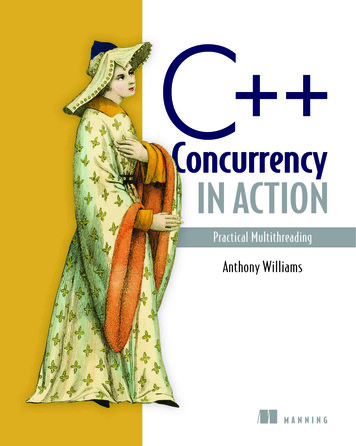
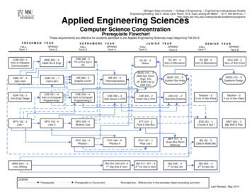
concurrent engineeringWhy a model? A parametric-model-basedapproach allows generic models of variousmission/technological scenarios to becharacterised for the study being performed.A parametric approach supports fastmodification and analysis of new scenarios,which is essential for the real-time process. Itacts as a means to establish and fix the groundrules of the design and to formalise theresponsibility boundaries of each domain.Once a specific model is established, it is usedto refine the design and to introduce furtherlevels of detail.support office space. The equipment andlayout of the CDF is designed to facilitate thedesign process, the interaction, the cooperation and the involvement of thespecialists. In particular, the disciplines with themost frequent interaction or other affinities (e.g.data/model sharing) are located close to eachother. The central table is dedicated to thecustomer, support specialists and consultants.In front, large projection screens can show thedisplay of each workstation, so that thespecialists can present design options orproposals and highlight any implicationsimposed on, or by, other domains. Videoconferencing equipment is installed to allowteam members to participate in sessions fromremote sites.A first activity in the modelling process is toacquire or establish the model suited to themission scenario before it can be parameterised to perform the iterative designprocess. Each model consists of an input,output, calculation and results area. The inputand output areas are used to exchangeparameters with the rest of the system (i.e.other internal and external tools and models).The calculation area contains equations andspecification data for different technologies inorder to perform the actual modelling process.The results area contains a summary of thenumeric results of the specific design to beused for presentation during the designprocess and as part of the report at the end ofthe study.The software infrastructureAn infrastructure to implement the ConcurrentDesign Facility outlined above requires:– tools for the generation of the model– integration of the domain models with ameans to propagate data between modelsin real time– a means to incorporate domain-specifictools for modelling and/or complex calculations– a documentation-support system– a storage and archiving capability.The infrastructure must allow its users to:– work remotely from the Facility both withinESTEC and in other centres especiallyESOC and ESA Headquarters– exchange information easily between thenormal office working environment and theFacility environment.The facilityThe team of specialists meets in theConcurrent Design Facility (CDF) to conductdesign sessions. The accommodationcomprises a design room, as illustrated inFigure 2, plus a meeting room and project-CADRISKSYSTEMPOWERCOMMSCOSTOPS &GROUNDSYSTEMSCONFIGURATION& ISSIMULATION&VISUALISATIONPROPULSIONFigure 2. Constitution andlayout of the ESTECConcurrent Design Facility
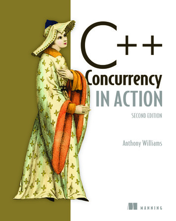
rbulletin 99 — september 1999 bullIn creating such an infrastructure to support theconcurrent-design process, a number ofimportant issues had to be considered.Due to the experimental nature of the exercise,it was decided to use existing equipment andtools to build up the facility. The architecture ofthe system required workstations for thedevelopment of the project model and asupporting documentation system. Thesolution adopted was to base the infrastructureon the products already available either withinthe office-automation domain or within thetechnical domain of the participating engineers.As a result, no additional licences were requiredfor the major software products to beemployed. Low-power personal computers (75to 133 MHz) were used to host the officeautomation products.Only two months were available to prepare aworking system, leaving no time for the trainingof users. Use of existing tools with which thestaff were already familiar was the only solutionto this problem.Table 2 identifies the general tools chosen asbasic infrastructure items used by all teammembers, while Table 3 identifies the domainspecific tools used by the domain experts.Although driven by the constraints identifiedabove, the choice of tools has, in fact, provento be satisfactory when looking to the future.Table 2. General toolsFunctionTools UsedDocumentation storage & archivingElectronic communication within the teamStorage area for all data filesSystem modellingProject documentationRemote audio/visual communicationLotus Notes databaseLotus Notes mailNT file serverExcel spreadsheetsMS-WordVideo conferencing & MS-NetmeetingTable 3. Domain-specific toolsDomainTools usedStructural design, configuration & accommodationThermalAOCSMission analysisMission simulation & visualisationProgrammaticsCost modelling and estimationCATIAESATAN & ESARADMatrix XIMATEUROSIMMS-ProjectECOM cost/technical database& small-satellite cost modelUsing tools that are already part of theAgency’s infrastructure brings many benefits.For the system model, the choice of MicrosoftExcel spreadsheets was driven not only by itsavailability and the existing skills of the team,but by the fact that relevant work had alreadybeen performed under an ESA contract* in1996. A fundamental decision was taken tosplit the system model into components thatmirrored the domains of expertise of the teammembers, allowing work to be performed onthe modelling independently and in parallel andwithout the reliance on a single modellingexpert. This raised the need for a mechanism toexchange relevant data between domains in acontrolled manner. This was solved bypreparing a shared workbook to integrate thedata to be exchanged, with macros to handlethe propagation of new data in a controlledway.Figure 3 shows the architecture of the model.A significant output of any pre-Phase-A study isthe Study Report. The use of Microsoft Word allowed each engineer to prepare their sectionof the report as a sub-document that was thenincorporated into the master document,prepared in accordance with the ESA standarddocument template.The use of Lotus Notes as the mail anddocument repository tool gave ESA-wideaccess to the project information, providing(subject to access control) a facility to browse,access or contribute to the studydocumentation.The domain-specific tools brought by eachexpert had to be integrated into theinfrastructure of the facility. For the purposes ofthe initial study, data exchanges between thetools and the Excel model were kept to aminimum, to avoid cost and the delay incurredby software development. In cases where toolswere also implemented as spreadsheets, theinterfacing was simple and even automated. Inother cases, input received by a domain modelhad to be transferred manually to applicationsrunning on separate workstations, with theresults transferred again by hand into the Excelmodel for further processing or propagation toother domains.* Spacecraft Modelling: A Spacecraft IntegratedDesign Model - System Requirements Documentand User Manual, Matra Marconi Space (UK),December 1996.
concurrent engineeringFigure 3. Architecture of thesoftware modelEach domain workbook is comprised, as a minimum, of an input, output, model and resultsworksheet. In practice, multiple sheets are used for the modelling to give clarity to the majorparts of the model and to ease display of the model during design sessions. The input andoutput sheets implement the data exchange with other domains as well as external tools. Figure3 shows the conceptual architecture.During a design session, discussion will lead to the necessity to perform an update to the modelto reflect decisions or test hypotheses (e.g. to demonstrate the impact of changing the type ofsolar cells). Key parameters controlling the selection of the technology would be updated in theappropriate domain model. This will result in a new set of output parameters that must initiallybe restricted to the generating domain and not propagated to the rest of the system. If adecision is taken to propagate the data, then the locally held values are saved in the domainoutput sheet. The next step is to update the shared data area by propagating the domain outputsheet. At this stage, the data is available to other domains should they decide to use it (i.e. otherdomain models are not triggered). The last step is to trigger the affected domains to read thenew input data and to execute the model.This process must be repeated until the impact of the change has been propagated to the pointwhere iterations no longer have a significant effect. Clearly, the possibility for several, if notendless, iterations arises since two or more domains may be affected by each other’s output!This aspect of the infrastructure is a candidatefor improvement in the longer term and willenhance the concurrency of the designprocess. An example of such an improvementwould be the export of geometrical 3-Dspacecraft-configuration data to the simulationsystem, which uses geometric models for thespacecraft visualisation.ConclusionsAs often happen, the adaptation of a processto take full advantage of a new method is notstraightforward. For a time the process goeson as before, taking partial advantage of thenew method, but suffering from resistance tochange. Adopting a new method often needsa change in the mentality of the peopleinvolved, and only when these actors areconvinced can the method itself be fullyexploited. Furthermore, the use of the methodmay well result in the need for organisationalchanges external to the facility, in order toobtain maximum benefit.
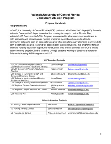
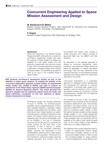
rbulletin 99 — september 1999 bullFigure 4. The study team,gathered in the ESTECConcurrent Design FacilityThe iterative approach to the mission designallows the depth of the final product to becontrolled. It is possible to study a mission at avery high level in a very short time, or to goto detailed design over a longer period.Furthermore, capturing the design in a modelallows breaks in the programme of work forreflection, without the loss of informationduring the inactive period.The experiment has shown the benefits ofcentralising system-engineering tools as partof an integrated facility. This approach can givefocus to developments that in the past havebeen mostly independent. The approach alsolends itself to activities other than pre-Phase-Amission assessments. The same principlescould be applied to individual module/subsystem/instrument design and extended tocover other phases of the mission developmentlife-cycle, in line with the goals of concurrentengineering in general. Use of the facility tosupport training, reviewing and proposalevaluation could also be investigated.The case study has indicated that aconceptual design could be performed in amuch shorter time and at a lower cost thanwith traditional methods. Clearly, furtherresources would be needed to implement apermanent facility, with fully trained users andpopulated databases, before such gains canbe fully exploited.The success of the first study output wasconfirmed by a thorough review conducted byan ESA Board using the procedures normallyfollowed in the Agency, but taking advantageof the model and the facility, for bothpresentation and explanation of the chosendesign. The study results were judged by thereview team to be more detailed and internallyconsistent that those produced via theclassical approach.The CESAR study alone is, of course, notsufficient for a complete validation of themethod. More studies, preferably in differentmission domains, should allow a betterassessment of the consequences of adoptingthe method in general, plus identification of theadvantages and disadvantages of theapproach. A second study is now in progressin the ESTEC CDF for an ESA solar-orbitingscience mission, and others are currently beingproposed.Finally, a decision to set up a permanent facilityshould be addressed, once sufficientexperience with the method has beenobtained.AcknowledgementsThe authors wish to thank:– the team of specialists who enthusiasticallysupported the first study– the participants from the Italian SpaceAgency (ASI) for their support and fruitful cooperation.Fruitful discussions with and inputs from theAerospace Corporation’s Concept DesignCenter and NASA/JPL’s Team X are alsogratefully acknowledged.r
studies in a more effective (i.e. concurrent) way. The concurrent-engineering approach is based on five key elements: - a process - a multidisciplinary team - an integrated design model - a facility, and - a software infrastructure. The process The conceptual model of the design process is shown in Figure 1, which highlights the fact .