Transcription
UNIT 4 FUNDAMENTALS OF PARTPROGRAMMINGFundamentals ofPart 3Types of Part Programming4.2.1Manual Part Programming4.2.2Computer Aided Part ProgrammingFundamental Elements for Developing Manual Programming4.3.1Type of Dimensioning System4.3.2Axes Designation4.3.3NC Words4.3.4Standard G and M Codes4.3.5Tape Programming Format4.3.6Machine Tool Zero Point Setting4.3.7Coordinate Word4.3.8Parameter for Circular Interpolation4.3.9Spindle Function4.3.10 Feed Function4.3.11 Tool Function4.3.12 Work Settings and Offsets4.3.13 Rapid Positioning4.3.14 Linear Interpolation4.3.15 Circular Interpolation4.3.16 Circular Interpolation4.4Symbols Used4.5Part Program for Lathe Operation4.6Part Program for Machining Centres (Milling)4.7Fixed Cycle/Canned Cycle4.8Do-Loops4.9Subroutine4.10 Summary4.11 Answers to SAQs4.1 INTRODUCTIONTypes of part programming, Computer aided part programming, Part programmingmanual, Part programme using sub routines, do loops and fixed cycles are described inthis Unit.ObjectivesAfter studying this unit, you should be able to understand , , , and .31
CNC Machines4.2 TYPES OF PART PROGRAMMINGThe part program is a sequence of instructions, which describe the work, which has to bedone on a part, in the form required by a computer under the control of a numericalcontrol computer program. It is the task of preparing a program sheet from a drawingsheet. All data is fed into the numerical control system using a standardized format.Programming is where all the machining data are compiled and where the data aretranslated into a language which can be understood by the control system of the machinetool. The machining data is as follows :(a)Machining sequence classification of process, tool start up point, cuttingdepth, tool path, etc.(b)Cutting conditions, spindle speed, feed rate, coolant, etc.(c)Selection of cutting tools.While preparing a part program, need to perform the following steps :(a)Determine the startup procedure, which includes the extraction ofdimensional data from part drawings and data regarding surface qualityrequirements on the machined component.(b)Select the tool and determine the tool offset.(c)Set up the zero position for the workpiece.(d)Select the speed and rotation of the spindle.(e)Set up the tool motions according to the profile required.(f)Return the cutting tool to the reference point after completion of work.(g)End the program by stopping the spindle and coolant.The part programming contains the list of coordinate values along the X, Y and Zdirections of the entire tool path to finish the component. The program should alsocontain information, such as feed and speed. Each of the necessary instructions for aparticular operation given in the part program is known as an NC word. A group of suchNC words constitutes a complete NC instruction, known as block. The commonly usedwords are N, G, F, S, T, and M. The same is explained later on through examples.Hence the methods of part programming can be of two types depending upon the twotechniques as below :(a)Manual part programming, and(b)Computer aided part programming.4.2.1 Manual Part ProgrammingThe programmer first prepares the program manuscript in a standard format.Manuscripts are typed with a device known as flexo writer, which is also used to typethe program instructions. After the program is typed, the punched tape is prepared on theflexo writer. Complex shaped components require tedious calculations. This type ofprogramming is carried out for simple machining parts produced on point-to-pointmachine tool.To be able to create a part program manually, need the following information :32(a)Knowledge about various manufacturing processes and machines.(b)Sequence of operations to be performed for a given component.(c)Knowledge of the selection of cutting parameters.(d)Editing the part program according to the design changes.(e)Knowledge about the codes and functions used in part programs.
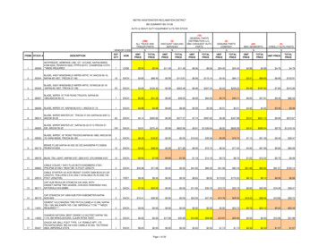
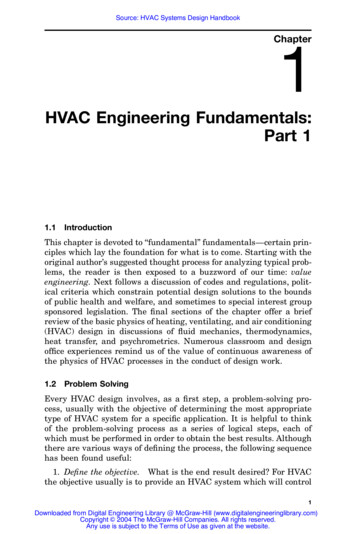
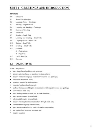
4.2.2 Computer Aided Part ProgrammingFundamentals ofPart ProgrammingIf the complex-shaped component requires calculations to produce the component aredone by the programming software contained in the computer. The programmercommunicates with this system through the system language, which is based on words.There are various programming languages developed in the recent past, such as APT(Automatically Programmed Tools), ADAPT, AUTOSPOT, COMPAT-II, 2CL,ROMANCE, SPLIT is used for writing a computer programme, which has English likestatements. A translator known as compiler program is used to translate it in a formacceptable to MCU.The programmer has to do only following things :(a)Define the work part geometry.(b)Defining the repetition work.(c)Specifying the operation sequence.Over the past years, lot of effort is devoted to automate the part programme generation.With the development of the CAD (Computer Aided Design)/CAM (Computer AidedManufacturing) system, interactive graphic system is integrated with the NC partprogramming. Graphic based software using menu driven technique improves the userfriendliness. The part programmer can create the geometrical model in the CAM packageor directly extract the geometrical model from the CAD/CAM database. Built in toolmotion commands can assist the part programmer to calculate the tool pathsautomatically. The programmer can verify the tool paths through the graphic displayusing the animation function of the CAM system. It greatly enhances the speed andaccuracy in tool path generation.Figure 4.1 : Interactive Graphic System in Computer Aided Part Programming4.3 FUNDAMENTAL ELEMENTS FORDEVELOPING MANUAL PART PROGRAMMEThe programmer to consider some fundamental elements before the actual programmingsteps of a part takes place. The elements to be considered are as follows :4.3.1 Type of Dimensioning SystemWe determine what type of dimensioning system the machine uses, whether an absoluteor incremental dimensional system which has been explained in Unit 2.33
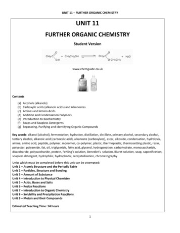
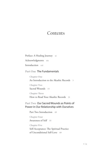
CNC Machines4.3.2 Axis DesignationThe programmer also determines how many axes are availed on machine tool. Whethermachine tool has a continuous path and point-to-point control system that has beenexplained in Unit 2.4.3.3 NC WordsThe NC word is a unit of information, such as a dimension or feed rate and so on. Ablock is a collection of complete group of NC words representing a single NCinstruction. An end of block symbol is used to separate the blocks. NC word is where allthe machining data are compiled and where the data are translated in to a language,which can be understood, by the control system of the machine tool.Block of InformationNC information is generally programmed in blocks of words. Each word conformsto the EIA standards and they are written on a horizontal line. If five completewords are not included in each block, the machine control unit (MCU) will notrecognize the information; therefore the control unit will not be activated. Itconsists of a character N followed by a three digit number raising from 0 to 999.Figure 4.2 : A Block of InformationUsing the example shown in Figure 4.2. The words are as follows :N001 – represents the sequence number of the operation.G01 – represents linear interpolation.X12345 – will move the table in a positive direction along the X-axis.Y06789 – will move the table along the Y-axis.M03 – Spindle on CW and; – End of block.4.3.4 Standard G and M CodesThe most common codes used when programming NC machines tools are G-codes(preparatory functions), and M codes (miscellaneous functions). Other codes such as F,S, D, and T are used for machine functions such as feed, speed, cutter diameter offset,tool number, etc. G-codes are sometimes called cycle codes because they refer to someaction occurring on the X, Y, and/or Z-axis of a machine tool. The G-codes are groupedinto categories such as Group 01, containing codes G00, G01, G02, G03, which causesome movement of the machine table or head. Group 03 includes either absolute orincremental programming. A G00 code rapidly positions the cutting tool while it isabove the workpiece from one point to another point on a job. During the rapid traversemovement, either the X or Y-axis can be moved individually or both axes can be movedat the same time. The rate of rapid travel varies from machine to machine.34
The total numbers of these codes are 100, out of which some of important codes aregiven as under with their functions :Fundamentals ofPart ProgrammingG-Codes (Preparatory Functions)CodeFunctionG00Rapid positioningG01Linear interpolationG02Circular interpolation clockwise (CW)G03Circular interpolation counterclockwise (CCW)G20Inch input (in.)G21Metric input (mm)G24Radius programmingG28Return to reference pointG29Return from reference pointG32Thread cuttingG40Cutter compensation cancelG41Cutter compensation leftG42Cutter compensation rightG43Tool length compensation positive ( ) directionG44Tool length compensation minus (-) directionG49Tool length compensation cancelsG 53Zero offset or M/c referenceG54Settable zero offsetG84canned turn cycleG90Absolute programmingG91Incremental programmingNote : On some machines and controls, some may be differ.M-Codes (Miscellaneous Functions)M or miscellaneous codes are used to either turn ON or OFF different functions,which control certain machine tool operations. M-codes are not grouped intocategories, although several codes may control the same type of operations such asM03, M04, and M05, which control the machine tool spindle. Some of importantcodes are given as under with their function s:CodeFunctionM00Program stopM02End of programM03Spindle start (forward CW)M04Spindle start (reverse CCW)M05Spindle stopM06Tool changeM08Coolant onM09Coolant off35
CNC MachinesM10Chuck - clampingM11Chuck - unclampingM12Tailstock spindle outM13Tailstock spindle inM17Tool post rotation normalM18Tool post rotation reverseM30End of tape and rewind or main program endM98Transfer to subprogramM99End of subprogramNote : On some machines and controls, some may be differ.4.3.5 Tape Programming FormatBoth EIA and ISO use three types of formats for compiling of NC data into suitableblocks of information with slight difference.Word Address FormatThis type of tape format uses alphabets called address, identifying the function ofnumerical data followed. This format is used by most of the NC machines, alsocalled variable block format. A typical instruction block will be as below :N20 G00 X1.200 Y.100 F325 S1000 T03 M09 EOB orN20 G00 X1.200 Y.100 F325 S1000 T03 M09;The MCU uses this alphabet for addressing a memory location in it.Tab Sequential FormatHere the alphabets are replaced by a Tab code, which is inserted between twowords. The MCU reads the first Tab and stores the data in the first location thenthe second word is recognized by reading the record Tab. A typical Tab sequentialinstruction block will be as below : 20 00 1.200 .100 325 1000 03 09Fixed Block FormatIn fixed block format no letter address of Tab code are used and none of wordscan be omitted. The main advantage of this format is that the whole instructionblock can be read at the same instant, instead of reading character by character.This format can only be used for positioning work only. A typical fixed blockinstruction block will be as below:20 00 1.200 .100 325 1000 03 09 EOB 4.3.6 Machine Tool Zero Point SettingThe machine zero point can be set by two methods by the operator, manually by aprogrammed absolute zero shift, or by work coordinates, to suit the holding fixture or thepart to be machined.Manual SettingThe operator can use the MCU controls to locate the spindle over the desired partzero and then set the X and Y coordinate registers on the console to zero.36
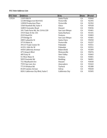
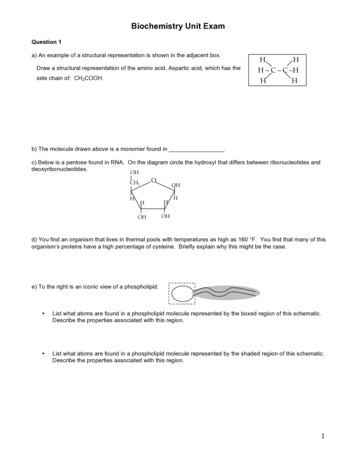
Fundamentals ofPart ProgrammingAbsolute Zero ShiftThe absolute zero shift can change the position of the coordinate system by acommand in the CNC program. The programmer first sends the machine spindle tohome zero position by a command in the program. Then another command tellsthe MCU how far from the home zero location, the coordinate system origin is tobe positioned.Figure 4.3 : Machine Tool Zero Point SettingR Reference point (maximum travel of machine)W Part zero point workpice coordinate systemM Machine zero point (X0, Y0, Z0) of machine coordinate systemThe sample commands may be as follows :N1 G28 X0 Y0 Z0 (sends spindle to home zero position or Return to referencepoint).N2 G92 X3.000 Y4.000 Z5.000 (the position the machine will reference as partzero or Programmed zero shift).4.3.7 Coordinate WordA co ordinate word specifies the target point of the tool movement or the distance to bemoved. The word is composed of the address of the axis to be moved and the value anddirection of the movement.ExampleX150 Y-250 represents the movement to (150, 250). Whether the dimensions areabsolute or incremental will have to be defined previously using G-Codes.4.3.8 Parameter for Circular InterpolationThese parameters specify the distance measured from the start point of the arc to thecenter. Numerals following I, J and K are the X, Y and Z components of the distancerespectively.4.3.9 Spindle FunctionThe spindle speed is commanded under an S address and is always in revolution perminute. It can be calculated by the following formula :Spindle Speed Surface cutting speed in m/min 1000π Cutter Diameter in mmExampleS1000 represents a spindle speed of 1000 rpm.37
CNC Machines4.3.10 Feed FunctionThe feed is programmed under an F address except for rapid traverse. The unit may be inmm per minute or in mm per revolution. The unit of the federate has to be defined at thebeginning of the programme. The feed rate can be calculated by the following formula :Feet Rate Chip LoadTooth No. of tooth Spindle speedExampleF100 represents a feed rate of 100 mm/min.4.3.11 Tool FunctionThe selection of tool is commanded under a T address. T04 represents tool number 4.4.3.12 Work Settings and O
4.2.1 Manual Part Programming 4.2.2 Computer Aided Part Programming 4.3 Fundamental Elements for Developing Manual Programming 4.3.1 Type of Dimensioning System 4.3.2 Axes Designation 4.3.3 NC Words 4.3.4 Standard G and M Codes 4.3.5 Tape Programming Format 4.3.6 Machine Tool Zero Point Setting 4.3.7 Coordinate Word 4.3.8 Parameter for Circular Interpolation 4.3.9 Spindle Function