Transcription
TS110 DISPLAY MANUALPro Refrigeration, Inc
ii Pro Refrigeration, IncTable of Contents1PrefaceillDisclaimer . . . . . . . . . . . . . . . . . . . . . . . . . . . . . . illManufacture Information. . . . . . . . . . . . . . . . . . . . . . . illCustomer Service. . . . . . . . . . . . . . . . . . . . . . . . . . . ill2Quick Start1TS110 Hardware Overview . . . . . . . . . . . . . . . . . . . . . . . 1Quick Start Guide (Network Installation) . . . . . . . . . . . . . . . . . 23Installation4Wiring with the CR110 Refrigeration Controller. . . . . . . . . . . . . . 4Wiring with the RGX Communications Gateway Card . . . . . . . . . . . 54TS110 Screen & Operation Overview6Logging in. . . . . . . . . . . . . . . . . . . . . . . . . . . . . . 6HomeScreen . . . . . . . . . . . . . . . . . . . . . . . . . . . . . 6Detail Screen. . . . . . . . . . . . . . . . . . . . . . . . . . . . . 7Component Test Screen. . . . . . . . . . . . . . . . . . . . . . . . . 7Setting INF File. . . . . . . . . . . . . . . . . . . . . . . . . . . . 8System Parameters Screen . . . . . . . . . . . . . . . . . . . . . . . 8
Table of Contents 1iiiPrefaceThis manual is intended to be used in conjunction withPro Refrigeration’s TS110 touch screen display.This manual will guide you through the process of installing, wiring and configuring your TS110 display.Note: Check the following URL for the latestversion of this manual and other Pro Refrigeration, Inc product 10 SummaryThe TS110 display is intended to be used with ProRefrigeration’s CR110 refrigeration card and the RGXcommunication gateway card. The TS110 display cancommunicate with up to 8 CR110 cards through a RS485 communications bus.The TS110 display runs on Microsoft Windows CE 5.Offered By:Pro Refrigeration, Inc.Pro Refrigeration is located in Auburn WA. Auburnis located 30 miles from Seattle, WA in the shadow ofMt. Rainier.Physical Address:326 8th ST SWAuburn, WA 98001www.prochiller.comMailing Address:PO BOX 1528Auburn, WA 98071-1528Telephone: 253-735-9466Fax: 253-735-2631Customer ServicePlease feel free to contact customer service with anyquestions pertaining to this or any other Pro Refrigeration, Inc product.Customer Support Hours:Monday-Friday7am-5pm (Pacific Standard Time)Telephone: 253-735-9466Fax: 253-735-2631Email: service@prorefrigeration.com
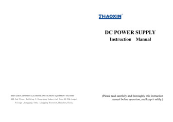
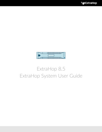
Quick Start Guide TS110 HARDWARE OVERVIEWLAN: The Ethernet port on theTS110 allows you to connect theRGX communications gateway toyour existing computer networkgiving you the ability to access theTS110 remotely with VNC software.Please see the Quick Start section forinformation on setting the TS110’sIP address.Compact Flash: This compartment holds a compact flash storage card which contains all of thePro Interface software, log files, &INF files. The Storage Card canbe accessed by typing “\StorageCard” into the run dialog.COM3: The COM3 9-PIN serialport is used for RS485 communication with the CR110 or RGX. Referto the installation section for wiringinstructions. USB Port: When USB device isinserted it will appear on TS110as “USB Hard Disk” it can beaccessed by typing “\USB HardDisk” into the run dialog.24V Power Terminal: This terminalshould be connected to a 24V ACor DC power source.Power Switch: Verify that thepower switch is in the ON positionprior to operation.
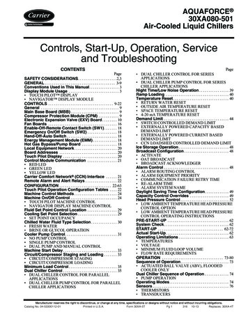
Pro Refrigeration, IncTS110 QUICK START GUIDETap on the Windows Start button, tap “Settings” and tap“Network and Dial-up Connections”.(Network Installation)The quick start guide is designed to be used in conjunction with a TS110 Touch Screen Display that wasfactory installed on a Pro Refrigeration, Inc ChillerSystem. As such, this guide assumes that all programming and non-network related wiring is complete. Ifyou have purchased the TS110 display to add to anexisting Chiller System please refer to section 3 for installing and wiring your RGX TS110 display. The logininformation to gain access to your systems operatingparameters from the login screen is provided below.PasswordsSecurity Level1111View Only2222View & Control3333View, Control & ConfigureTap and hold on the “SMSC91181” adapter, on the menumove your finger down to “Properties” remove your fingerfrom the screen to select.STEP 1 - Connect Ethernet CableConnect an Ethernet cable from the Ethernet port onthe back of your TS110 display to an open port on yournetwork switch or router.STEP 2 - Set IP AddressTo allow the TS110 display to communicate with yournetwork you will need to give it an available IP addresson your network. To set the IP address follow the stepsand pictures outlined below.Tap on the “Help” drop down menu and tap“Toggle Screen Size”, as seen in the picture below.Tap the “Specify an IP address” button, tap in each fieldbelow and set them to your desired IP address and networksettings using the on screen keyboard. You may need to movethe keyboard (tap & drag) to enter values in the lower fields.Tap “OK” when finished.
Quick Start Guide Tap X to close the “Network and Dial-up Connections” window, tap the “Help” drop down menu and tap“Toggle Screen Size” again to return your window to itsoriginal screen size.STEP 3 - Redirect Ports To TS110To allow remote connections to access to your TS110from outside your network you will need to redirect thefollowing UDP & TCP ports from your router to theaddress you just configured on your TS110 display.TS110: 502, 5900 & 5800UDP: 4001STEP 4 - Accessing Your TS110You should now be able to access your TS110 from anycomputer using your external IP address and port 5800in a web browser as shown below.http://YOUR EXTERNAL IP:5800This will launch a Java VNC client dialog that willconfirm the IP address you entered above, click OK.You will then be prompted for a password. The defaultpassword is “prochill”.You should now have a window that shows the TS110display. You can navigate through the display as if youwere in front of it. See the picture below for an exampleof VNC remote control window.
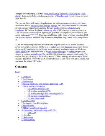
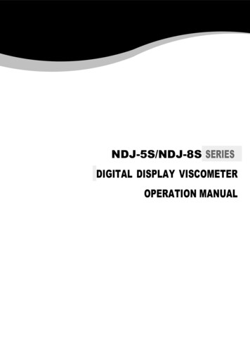
Pro Refrigeration, IncWIRING WITH THE CR110 CONTROLLERThe depiction below shows the connections that need to be made to allow communication between the TS110display and the CR110 controller. If you do not have an RGX card use the following wiring scheme.J11: Connect to 24V AC or DCPower Source.J12: (optional) Connect for MODBUS RS-232 communication.J10: (optional) Connect for MODBUS RS-485 communication.Note: J10 and J12 may notbe connected simultaneously.To switch between J10 or J12move switch S1 to either 485for J10 or 232 for J12.J7: Connect to COM 2 on the G55Interface. Also can be used as aMODBUS slave port (Baud rateadjustable, default 9600kps).24V Power Terminal: This terminalshould be connected to a 24V ACor DC power source.COM3: Using a 2 conductor cable with shieldconnect a 9-PIN connector to one end. Connect wires to the pins as show in Figure 3-1.Connect the other end to a CR110 controllercard. Connect red ( ) and black (-) cables to J13and the shield (C) to J7 on the CR110. If youare using multiple CR110 Cards make connections to the first card only as the communication wires are daisy chained between CR110cards.Figure 3-1 COM3 Pin Configuration
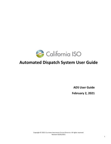
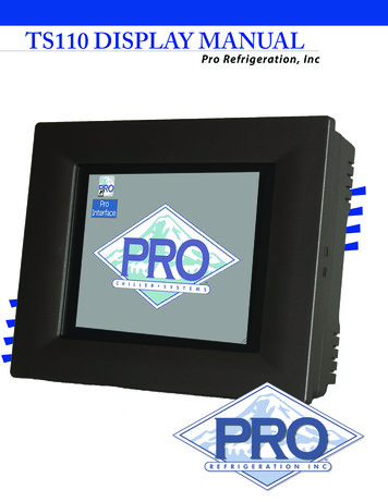
Installation WIRING WITH THE RGX COMMUNICATIONS CARDThe depiction below shows the connections that need to be made to allow communication between the RGX andTS110 display. If you have a RGX card use the following wiring scheme.24V Power Terminal: This terminalshould be connected to a 24V ACor DC power source.COM3: Using a 2 conductor cable with shieldconnect a 9-PIN connector to one end. Connect wires to the pins as show in Figure 3-1.Connect the other end to the RGX communications Card. Connect the red ( ) , black(-) and shield (G) wires to J7 (MAIN) onthe RGX card. Using the RGX web-interfacechange the J7 port settings to the following:Function: BCS SERVERFigure 3-1 COM3 Pin ConfigurationBuad Rate: 9600
Pro Refrigeration, IncTS110 Screen & Operation OverviewThis section contains a summary of each screen withinthe TS110 display. Details will be given on each settingto give a better understanding of how it can be effectively used in your specific deployment.Default InformationBy default the TS110 display has three users with different levels of access. Below are the default user logininformation.PasswordSecurity Level1111View Only2222View & Control3333View, Control & Configureton (SP), Outlet Temperature (Outlet), Inlet Temperature (Inlet) and Output Percentage (Out). The rest ofthe rows will populate to the number of compressors onyour chiller system. The rows will contain a CompressorButton and will display the current mode of that refrigeration circuit. If the number of compressors showndoes not match the number on your Pro Chiller Systemplease see Set INF File in the App Menu section. SeeFigure 4-2.The default IP address is 192.168.1.51.Login ScreenTap the “LOG IN” button. A numerical keypad willdisplay allowing you to enter a password. Enter any ofthe default passwords shown above. See Figure 4-1.Figure 4-2 Home Screen Set Point Button: By tapping the set point button onthe Home Screen you can adjust the set point for compressor 1. A numerical keypad will popup, tap the valueof the desired set point and tap “Enter”. The SP valuewill update on the Home Screen. See Figure 4-3.Figure 4-1 Login ScreenHome ScreenOnce you have successfully logged-in the Home Screenwith be displayed. If the Home Screen is not displaying the correct number of compressors for your systemsee Set INF File in the App Menu section. The HomeScreen’s top row displays a Set Point Temperature But-Figure 4-3 Adjust Set Point Compressor Buttons: Each compressor’s name is abutton that will take you to the Details Screen for thatcompressor. (ex: COMP 1, COMP 2 , etc)
TS110 Screen & Operation Overview Details ScreenThe Details Screen contains a fully customizable set of set offields specific to the selected compressor circuit. The top rowdisplays the time, Pervious Button, Next Button, the compressor number you are viewing and the mode of it’s refrigeration circuit. The remaining rows display Discharge Pressure(Dis P), Suction Pressure (Suc P), Suction Superheat (SucSH), Set Point Button (SP), Outlet Temperature (Outlet),Inlet Temperature (Inlet), Output Percentage (Out), OutputStatus (Output Status), Input Status (Input Status), LeadCompressor (Lead). See Figure 4-4. Component Test ScreenThe Component Test Screen allows you to manually poweron the CR110 outputs to each component within the selected circuit. See Figure 4-5.Caution: The buttons on this screen shouldbe used only as electrical verification prior tosystem operation. Do not use while system isrunning.Figure 4-5 Component Test ScreenFigure 4-4 Details Screen Previous Button: The Previous button will take youback to the Home Screen. Next Button: The Next button will take you to theComponent Test Screen. Set Point Button: By tapping the set point buttonon the Details Screen you can adjust the set point forcompressor circuit you have selected. A numericalkeypad will popup, tap the value of the desired set pointand tap “Enter”. The SP value will update on the HomeScreen. See Figure 4-3. Reset Button: By tapping the RESET button youwill reset the current operation mode of the CR110.This will clear any CR110 alarms if the source of thealarm has been corrected. Previous Button: The Previous button will take youback to the Details Screen. Next Button: The Next button will take you to theSystem Parameters Screen. C Fan 1 Button: Energizes CR110 output for condenser fan 1. C Fan 2 Button: Energizes CR110 output for condenser fan 2. C Fan 3 Button: Energizes CR110 output for condenser fan 3. Circ P 2 Button: Energizes CR110 output for circulation pump 2. COMP 2 Button: Energizes CR110 output for compressor 2. LLS Button: Energizes CR110 output for the liquidline solenoid valve. UL1 Button: Energizes CR110 output for compressorunloader 1. UL2 Button: Energizes CR110 output for compressorunloader 2.
Pro Refrigeration, IncSystem Parameters ScreenThe System Parameters Screen contains a scrollable list ofsystem operating parameters specific to the selected circuit.You are able to scroll the list and tap any parameter to adjustits value. Please reference Pro Refrigeration’s CR110 manualfor a list of factory recommended settings specific to yoursystem’s configuration. See Figure 4-6. Set INF: This option allows you to specify the INFfile that matches the number of circuits on your chillersystem. By default you should have configurations onthe storage card for 1 to 5 compressors. If you need aconfiguration not provided please contact Pro Refrigeration’s technical support. To change the INF file tapthe Set INF option in the App menu, an open dialogwill popup, tap the Storage Card icon to navigate to itsdirectory, you can now tap twice to select the properINF for your system from the options provide on thestorage card (ex “Pro C1 revB ver04B”, “Pro C1C2revB ver04B”, “Pro C1C2C3 revB ver04B”, etc. WhereC# corresponds to the number of compressors on yoursystem). See Figure 4-8 below.Figure 4-6 System Parameters Screen Previous Button: The Previous button will take youback to the Component Test Screen. Next Button: The Next button will take you to theHome Screen. Parameter List: Tap any setting in the list and youwill be given a numerical pad to adjust it’s value.App MenuThe App Menu is at the top left-hand corner of the screenand provides a number of options that can be configured. Toaccess the drop down app menu tap the word App. Each option is discussed in detail below. See Figure 4-7.Figure 4-8 Load INF File Dialog Set Update Rate: This setting controls how often inseconds the TS110 display will request data from theCR110 controller. By taping this option you will begiven a numerical keypad to change the Update Rate. Set Comm Alarm Delay: This settings controls theamount of time in seconds that the TS110 will wait fora response from the CR110 controller before going intoa Comm Alarm state. Set UDP Port: The UDP port by default is set to 4001and should not be modified unless instructed to byPro Refrigeration. This setting is used for communication with the remote monitoring software used by ProRefrigeration’s technical support. Set COM 1: COM 1 is not used at this time.Figure 4-7 App Menu Set COM 2: COM 2 is not used at this time.
TS110 Screen & Operation Overview Set COM 3: This setting can be used to adjust thebuad rate at which the TS110 display communicateswith the CR110 controller. The default value is 9600.This should not be modified unless instructed by ProRefrigeration. Log Off: By tapping Log Off your screen will bereturned to the Log On prompt. Exit: Tapping Exit will close the program and returnyou to the desk top. To return to the program tap thePro Interface icon. See Figure 4-8 below.Figure 4-8 TS110 Desktop
Pro Refrigeration, Inc326 8th ST SWAuburn, WA 98001Tel: 800-845-7781Fax: 253-735-2631
factory installed on a Pro Refrigeration, Inc Chiller System. As such, this guide assumes that all program-ming and non-network related wiring is complete. If you have purchased the TS110 display to add to an existing Chiller System please refer to section 3 for in-stalling and wiring your RGX TS110 display. The login