Transcription
International Journal of Scientific & Engineering Research Volume 10, Issue 10, October-2019ISSN 2229-5518839Seismic Retrofit of Reinforced Concrete FrameStructuresT. S. MustafaDepartment of Civil Engineering, Shoubra Faculty of Engineering, Benha University,Shoubra St., Shoubra, Cairo, Egypt 108Abstract— One of the most effective systems in resisting the seismic force is the Moment Resisting Frame (MRF) that is used forreinforced concrete structures. Many of these structures are located in high seismic zones and have been designed based on out-dateddesign codes where is seismic forces are not considered or underestimated. Applying the updated seismic forces and parameters on suchstructures will not meet the safety requirements. Accordingly, the seismic retrofit for these structures is mandatory and cannot be avoided.Steel braces and concrete-steel composite elements are common solutions for enhancing the seismic behaviour of existing steel framestructures. In this paper, a numerical study for the seismic retrofit of RC structures that evaluates different possible techniques of existingreinforced concrete MRF structures are presented. Three multi-story buildings with different heights and located in a high seismic hazardzone have been investigated. Three retrofit techniques were introduced: (1) X-Steel braces, (2) buckling restrained composite braces, and(3) RC shear walls. The seismic performance enhancement of the studied structures was evaluated in terms of the structure’s fundamentalperiod, maximum inter-story drift and maximum base shear-to-weight ratios. Compared to the model without retrofitting, the retrofittedmodels showed increased stiffness, base shear and overturning moment capacities which accordingly decreased the story drift and roofdisplacement to the safe area. Additionally, retrofitting with buckling restrained braces resulted in the least lateral deformations and seismicforces.Index Terms— Reinforced concrete structures, Moment resisting frames, Seismic retrofit, Seismic performance, Dynamic analysis. Baseshear, RC shear walls.IJSER—————————— ——————————1 INTRODUCTIONEarthquake is a natural hazard that may cause extensivedamages especially to the built environment [1-5]. Earthquakesare random in nature and unpredictable, therefore, analysis ofthe structure under the action of earthquakes requires betterengineering approaches and tools. Hence, several improvements are continuously takes place in the earthquake engineering methodologies during the past few decades [6-11]. Seismicrisks affect a lot of important structures, such as utility systems(gas systems, telecommunication, and electric power) andtransportation infrastructures (airports, ports, roads and railway systems). Although USA is considered as one of thestrongest countries in terms of economic capacity, some citieswere struck by severe earthquakes that left a lot of causalitiesand damaged structures and that resulted in a complete paralysis of these cities. Examples of these disastrous earthquakes areSan Fernando (1971) and Northridge (1994) earthquakes.In order to reduce the number of human casualties, the safety of buildings has to be ensured. A complete damage of abuilding is allowed after a severe ground motion as long as nocollapse would occur (life safety performance level). Many ofexisting buildings do not meet such requirements of the currentseismic codes due to several reasons, such as; (a) Design ofstructure according to gravity loads only (b) the updates ofseismic codes and the intensity of seismic hazard, (c) anychange in the occupancy of existing structures, and (d) thestructure deterioration due to environmental effects. Accordingly, the seismic retrofit of these structures is an urgent need. Themain objective of this study is to evaluate the seismic performance of existing nominally ductile RC frame structures withdifferent heights when strengthened using different strengthening techniques. The structures which will be considered repre-sents buildings that have been designed according to pre-1970strength based code (ACI -1968) [12]. Strengthening will beconducted according to the current seismic maps and code recommendations. The existing RC frame structures represent lowand medium rise buildings that are located in the city of LosAngeles, California, USA.The considered strengthening techniques include (1) introducing RC shear walls, (3) installing steel braces, (3) installingbuckling restrained braces. To evaluate the seismic performanceenhancement of the studied buildings, the maximum inter-storydrift, the maximum roof displacement, and the maximum storyshear-to-weight ratio were obtained.2 NUMERICAL MODELLINGA seismic force resisting system (SFRS) must be able to provide the sufficient strength, stiffness, ductility, and energy dissipation capacity to withstand the design ground motion withinthe code limits. The seismic analysis of a structure shall be performed according to one of the following methods; EquivalentStatic Analysis, Response Spectrum Analysis (RSA), or TimeHistory Analysis. Equivalent Static Method in all design codeshas some restrictions and limitations of application, while theRSA could be conducted for any structure with an acceptablelevel of accuracy. Time History Analysis is more sophisticatedand can be used for high importance structures or for researchapplications. Description for the studied buildings and thestrengthening techniques suggested to upgrade their seismicperformance is illustrated here. Three systems were used tostrength the selected existing buildings; (a) adding a RC shearwalls, (b) adding steel braces, (c) adding buckling restrainedbraces. Lateral forces are resisted mainly by the new strengthen-IJSER 2019http://www.ijser.org
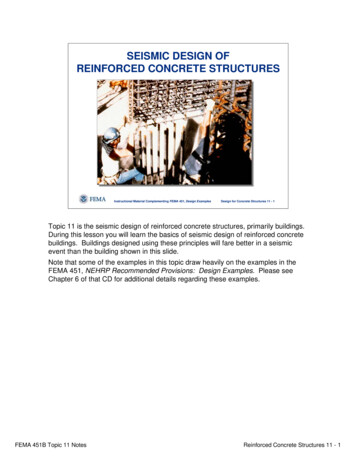
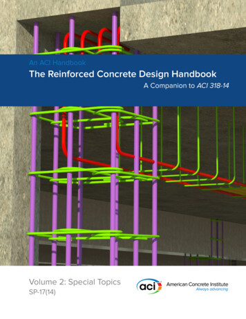
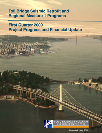
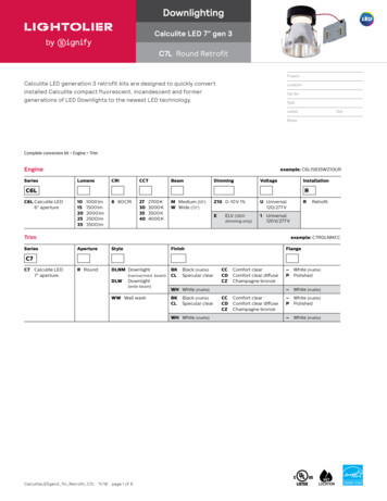
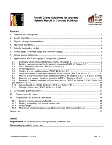
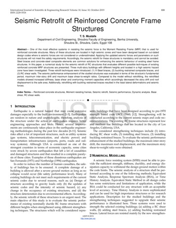
International Journal of Scientific & Engineering Research Volume 10, Issue 10, October-2019ISSN 2229-5518ing system along with the existing moment resisting frames.Linear dynamic analyses were conducted for the existing andretrofitted buildings using ETABS software (Computers andStructures, 2016).2.1 Description of the buildings under studyThree existing RC multi-story buildings with different heightswere considered in this study. The buildings were designedaccording to a pre-1970 design code (ACI -1968) [12]. Thebuildings are five-story, ten-story and fifteen-story high, andthat represent low, medium, and high rise buildings, respectively. The same floor plan was used for all buildings that consist of three equal bays in both directions, where the bay widthequals to 6.0 m. The story height is 3.0 m and the total heightof the three buildings is 15, 30 and 45 m, respectively. The columns’ reinforcement and concrete dimensions varied alongthe height of the building according to the change of axial loadacting on each group of columns. The beam concrete dimensions and steel reinforcement were assumed to be the same forthe entire building. The beam dimensions were set as350*600mm. The slab thickness in all models is set to 140 mm.2.2 Design Parameters2.2.1 Material Properties1.4 Properties of Response SpectrumThe response spectrum curve for Los Angeles city is shownin Fig. 2 and the properties of this spectrum are given below:ASCE -10 Retrofit Standards, San Francisco (34.05224 N,118.24368 W)Site Class B – “Rock”Section 2.4.1 – General Procedure for Hazard Due to GroundShaking5%/50-year maximum direction spectral response accelerationfor 0.2 sec and 1.0 sec periods, respectively: Where:S1 0.853 gThe authority having jurisdiction (not the USGS), site-specificgeotechnical data, and/or the default has classified the site asSite Class B, based on the site soil properties in according toASEC 7-10.The Values of Fa as a function of site classes and mapped shortperiods spectral response acceleration Ss 2.433g, for site Class B and Fa 1.The Values of Fv as a Function of Site Classes and MappedSpectral Response Acceleration at Period S1 0.853g and Fv 1.For Site Class B and S1 0.853g, Fv 1.SMS Fa*Ss 1.000 x 2.433 g 2.433 gSM1 Fv*S1 1.000 x 0.853 g 0.853 gSDS 2/3*SMs 2/3 x 2.433 g 1.622 gSD1 2/3*SM1 2/3x 0.853 g 0.569 gIJSERThe compressive strength of concrete has been assumed tobe of value fc’ 25.0 MPa for existing buildings and 40.0 MPafor the new concrete used for retrofitting. The yield strength ofsteel reinforcement is set as fy 400 MPa, and for steel members 340 MPa. The value of concrete density was consideredas 25 kN/m3 and the concrete Poisson’s ratio as 0.2. The modulus of elasticity for retrofit concrete was considered as 29.7GPa, 23.5 GPa for existing concrete and 200 GPa for steel.2.2.2 Design Loads840The structural elements of the existing buildings have beendesigned according to the American Concrete Institute manual(ACI 1968) [12]. The columns and beams were designed tocarry a slab thickness of 140 mm, a floor cover of 1.5 kPa, anequivalent uniform load from interior partition of 1.5 kPa, alive load of 2.0 kPa, and an exterior line load due to externalwalls and cladding of 10 kN/m [13].2.3 Properties of the selected siteThe three existing buildings were assumed to be in the cityof Los Angeles, California, USA. Los Angeles is considered tobe in a high seismic hazard zone as shown in Fig. 1 (Zone 4).Fig. 2. The Response Spectrum Curve for Los Angeles city1.5 Different Retrofit TechniquesIn the current research, the three existing RC buildings withdifferent heights located in Los Angeles area were strengthened using three seismic retrofit techniques: Strengtheningusing RC shear walls, strengthening using steel X-bracing andStrengthening using buckling restrained braces (BRB).2.5.1 Strengthening using RC shear wallsFig. 1. Seismic zone map (U.S. Geological Survey 2014)The existing building will be strengthened by adding RCshear wall in the middle bay of the external frames on thebuilding’s four sides. The thickness of the shear walls will beconsidered as 300 mm. The length of the walls is considered as3.0, 6.0 and 7.0 m long for the 5-, 10- and 15-story buildings,respectively. The wall dimensions were assumed to remainconstant along the building height. The Wall dimensions andreinforcement for each building are shown in Fig. 3. Thesevalues were derived from the seismic analysis and design tosatisfy the code requirements for deformations and strength,IJSER 2019http://www.ijser.org
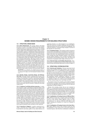
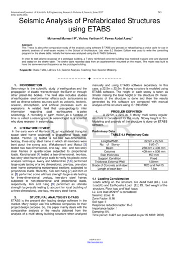
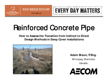
International Journal of Scientific & Engineering Research Volume 10, Issue 10, October-2019ISSN 2229-5518841and to maintain the existing frame elements safe under thedesign ground motion. The walls were designed as ductilewalls using R (Response modification factor) 6.0 as for special reinforced concrete shear wall, Cd (Deflection Amplification Factor) 5.0 due to the high seismicity of the buildinglocation [14-16].Fig. 5. The retrofit schemes by BRB braces for the studied buildings2. ANALYSIS RESULTSThe dynamic analysis of existing buildings showed that thebuildings collapsed at intensity levels of 44, 39, and 25% of thedesign response spectrum of Los Angeles city for the 5-, 10and 15-story buildings, respectively. Table 1 shows the resultsfor modal and dynamic analyses of the 5-, 10- and 15-storybuildings for existing and retrofitted buildings.Fig. 3. Details of the shear walls for the studied buildings2.5.2 Strengthening using steel X-bracingsSteel X-braces were installed in the external frames of thebuilding’s four sides for strengthening of existing buildingsalong the full height. The steel X-braces were installed in middle bay only for the 5-story building. While the braces wereinstalled in two bays for the 10- and 15-story buildings asshown in Fig. 4. The steel braces were connected with the existing RC frame as shown in Fig. 4. Used R (Response modification factor) 6.0 as for special steel concentrically bracedFrames, Cd (Deflection Amplification Factor) 5.0 [17].TABLE 1IJSERRESULTS OF EXISTING AND STRENGTHENED MODELS3.1 Fundamental PeriodFig. 4. Retrofitting using X-Steel braces for the studied buildings2.5.3 Strengthening using buckling restrained braces(BRB)Diagonal bucking restrained braces (BRBs) were installed tothe existing buildings to enhance their seismic performanceand reduce the buildings’ deformations. The BRB is connectedwith the existing RC frame as shown in Fig. 5. For all retrofitted buildings, the installed BRB consists of a steel I-beam ofdimensions 150 x 150 x10 mm imbedded in a square reinforced concrete section of dimensions 350 x 350 mm with steelreinforcement of 8T16. Used R (Response modification factor) 8.0 as for steel buckling restrained braced frames (BRB), Cd(Deflection Amplification Factor) 5.0 [18].Fig. 6 shows the fundamental period for the existing structures and the retrofitted ones for the 5-, 10- and 15-story buildings. It can be noticed from the figure that the proposed retrofit techniques reduced the fundamental period of existingstructures by almost 50%. This is due to the additional stiffness provided by introducing the shear walls or the braces tothe existing buildings. Hence, smaller story deformations andhigher seismic forces will be expected due to the seismic retrofit. The figure also shows a minor difference in the fundamental period of the retrofitted buildings, which indicates that theselected retrofit techniques provided similar additional stiffness to the existing buildings.IJSER 2019http://www.ijser.org
International Journal of Scientific & Engineering Research Volume 10, Issue 10, October-2019ISSN 2229-5518842Fig. 6. Fundamental period for existing and retrofitted buildingsFig. 7(b). Inter-story drift ratio for the 10-story building3.2 Inter-story drift ratioFig.s 7 (a), (b) and (c) presents the inter-story drift (I.D.) ratio for the 5-, 10- and 15-story existing buildings and thestrengthened ones. For existing buildings, the shown I.D. values were obtained at the maximum earthquake intensity thatcould be resisted that was 44, 39, and 25% of the design response spectrum of Los Angeles for the 5-, 10-, and 15-storybuildings, respectively. For the retrofitted buildings, the buildings were able to withstand 100% of the design intensity ofLos Angeles. As shown in the figure, it is noticed that the threeretrofit techniques were able to reduce the maximum I.D. ratiofor the three building heights even at a 100% of the designresponse spectrum. Fig. 8 shows the maximum I.D. ratio forthe existing buildings and the retrofitted ones. The figureshows that the buckling restrained braced buildings had theleast maximum I.D. ratio compared to other retrofit systems(shear walls and steel braces) for all building heights. The figure also shows that the maximum I.D. ratio for the retrofittedstructures did not exceed 1.20 percent. This value should notaffect the safety of the gravity load resisting system or thenon-structural elements (Adebar et. al. 2010).IJSERFig. 7(c). Inter-story drift ratio for the 15-story buildingFig. 8. Maximum I.D. ratio for the studied buildings3.3 Story DisplacementFig. 7(a). Inter-story drift ratio for the 5-story buildingFig.s 9 (a), (b), and (c) show the story displacement for the5-, 10- and 15-story buildings, respectively. The figures showthe values for buildings with different retrofit schemes at thedesign earthquake intensity of Los Angeles (LA), and for existing buildings at the maximum earthquake intensity resistedbefore a collapse mechanism occurs. Similar to the I.D. ratiocurves, the buckling restrained braces resulted in the least deformations compared to the other retrofit techniques. Fig. 10IJSER 2019http://www.ijser.org
International Journal of Scientific & Engineering Research Volume 10, Issue 10, October-2019ISSN 2229-5518843shows the maximum roof drift for the existing buildings andthe retrofitted ones, defined as the roof displacement dividedby the building total height. It can be noted from the figurethat the maximum roof drift for the retrofitted building withdifferent heights did not exceed the value of 0.84 percent.Fig.10. Maximum roof drift for the studied buildings3.4 Base ShearFig. 9(a). The story displacement of the 5-story buildingFig. 11 shows the base shear to weight ratio for the 5-, 10and 15-story existing buildings and the retrofitted ones withdifferent retrofit schemes. It can be concluded that the retrofittechniques resulted in a higher base shear compared to existing structures due to the additional stiffness provided by theretrofit techniques. The figure shows that using BRB resultedin a smaller base shear compared to the use of shear walls orsteel bracings for all building heights. However, similar resultswere obtained for the cases of shear walls and steel braces forall building heights.IJSERFig. 9(b). The story displacement of the 10-story buildingFig.11. Base shear to weight ratio for the existing and retrofitted buildings3.5 Overturning MomentsFig. 9(c). The story displacement of the 15-story buildingFig.s 12 (a), (b) and (c) shows the story overturning moments for the 5-, 10- and 15-story buildings for different retrofit schemes at the design earthquake intensity of LA, and forexisting buildings at the maximum earthquake intensity resisted before a collapse mechanism occurs. From the figures, itcan be seen that the BRB resulted in the least building’s baseoverturning moment for the 5- and 10-story buildings compared to the other techniques. On the contrary, for the 15-storybuilding, introducing shear walls has resulted in the least baseoverturning moment. Fig. 13 presents the base overturningmoment for existing buildings and the retrofitted ones. It canbe concluded that adding shear walls or braces to existingbuildings resulted in a higher seismic forces due to the addiIJSER 2019http://www.ijser.org
International Journal of Scientific & Engineering Research Volume 10, Issue 10, October-2019ISSN 2229-5518tional stiffness provided by the retrofitting systems, which ledto a higher base overturning moments.Fig.12(a). Story overturning moments of the 5-story building8444 CONCLUSIONIn this paper, there different strengthening techniques wereselected: (1) using X-steel bracing, (2) BRB and (3) RC shearwall to evaluate the effectiveness of these techniques on upgrading the seismic performance of RC frame structures.Three RC buildings with different heights were selected representing low and medium rise frames. Linear dynamic analysishas been conducted using the design response spectrum ofLos Angeles city represent earthquakes with high frequencycontents. The seismic performance enhancement of the analysed frames was evaluated based on the maximum inter-storydrift ratio, maximum roof displacement, maximum story shearto total weight ratio. Based on this analysis, the following concluded points can be drawn:1. Compared to the model without retrofitting, the retrofitted models showed reduced fundamental time period dueto the additional stiffness provided by the retrofitschemes. Additionally, the base shear and overturningmoment capacities have been increased by applying thedifferent retrofitting techniques.2. Due to the increased stiffness resulted from applying theretrofitting techniques, the story drift and roof displacement have been reduced to the safe margin.3. Compared to other retrofitting techniques, the BRB technique showed the least deformations and seismic forces.4. For all models, using RC shear wall as retrofitting technique reduced the straining actions on the columns whileusing X-steel bracing or BRB techniques increased thestraining actions on columns.IJSERFig.12(b). Story overturning moments of the 10-story buildingREFERENCES[1][2][3][4]Fig.12(c). Story overturning moments of the 15-story building[5][6][7]Fig.13. The base overturning moments of the studied buildings[8]Filiatrault, A., Lachapelle, E. and lamontagne, P., 1998. “Seismic performanceof ductile and nominally ductile reinforced concrete moment resisting frames.II. Analytical study” Canadian Journal of Civil Engineering, No. 25, p342-352Ghabarah A., Abou Elfath H., and Biddah, A., 1999. “Response-baseddamage assessment of structures” Journal of Earthquake Engineeringand Structural Dynamics, No.28, p79-104Heidebrecht, A.C. and Naumoski, N., 1999. “Seismic performance ofductile medium height reinforced concrete frame buildings design inaccordance with the provisions of the 1995 National Building Code ofCanada” Canadian Journal of Civil Engineering, No. 26, p606-617Ghabarah A., Abou Elfath H., 2001. “Rehabilitation of a reinforcedconcrete frame using eccentric steel bracing.” Journal of EngineeringStructures; No.23, p745-755Ghabarah A., El-Attar, M. and Aly, N.M., 2000. “Evaluation of retrofit strategies for reinforced concrete columns: a case study.” Journalof Engineering Structures; No.22, p490-501.Soundarya N. Gandhi, Y.P. Pawar, Dr. C. P. Pise, C.M. Deshmukh, S.S. Kadam, D. D. Mohite.,2017 “Strengthening of reinforced concrete and steel structure by using steel bracing systems”Kazak, I., Yakut, A., Gulkan, P., 2006. “Numerical simulation of dynamic shear wall test: A benchmark study” Journal of Computersand Structures, No. 84, p549-562Bush T. D., L. A. Wyllie and J. O. Jirsa. 1991. “Observations on twoseismic strengthening schemes for concrete frames”. EarthquakeSpectra 7(4): 511-527Umesh.R.Biradar, Shivaraj Mangalgi., 2014. “Seismic response ofIJSER 2019http://www.ijser.org
International Journal of Scientific & Engineering Research Volume 10, Issue 10, October-2019ISSN inforced concrete structure by using different bracing systems”Fazal U Rahman Mehrabi, Dr. D. Ravi Prasad., 2017. “Effects ofproviding shear wall and bracing to seismic performance of concretebuilding”Filiatrault, A., Lachapelle, E. and lamontagne, P., 1998. “Seismic performance of ductile and nominally ductile reinforced concrete momentresisting frames. I. Experimental study” Canadian Journal of Civil Engineering, No. 25, p331-341Tremblay, R., Leger, P. and Tu, J., 2001. “Inelastic seismic response ofconcrete shear walls considering P-delta effects” Canadian Journal ofCivil Engineering, No. 28, p640-655American Concrete Institute (ACI). Manual of concrete practice, part2. Committee 318- 1R-68, Detroit (USA); 1968American Society of Civil Engineering ASCE (2010), Minimum DesignLoads for Buildings and Other Structures (ASCE 7-10). USAKaplan H, Yilmaz S., Cetinkaya N., Atimtay E. Seismic strengtheningof RC structures with exterior shear walls. Sadhana, Springer- Verlag2011. Vol 36, No 1, p17-34Kaltakci M.Y., Arslan M.H., Yavuz G. Effect of Internal and External ShearWall Location on Strengthening Weak RC Frames. Scientia Iranica. Transaction A, Civil Engineering 2010. Vol 17, No 4, p312-323El-Sokkary, H. and Galal, K. (2009). “Analytical investigation of the seismicperformance of RC frames rehabilitated using different rehabilitation techniques” Engineering Structures, 9 (31), 1955-1966Galano, L. and Gusella, V., 1998. “Reinforcement of masonry walls subjected to seismic loading using steel X-bracing” Journal of Structural Engineering, Vol. 124, No. 8, p886-895Hamdy Abou-Elfath, Mostafa Ramadan and Fozeya Omar Alkanai (2016).“Upgrading the seismic capacity of existing RC building using buckling restrained braces” Alexandria Engineering Journal 56, 251-262IJSERIJSER 2019http://www.ijser.org845
of Los Angeles, California, USA. Los Angeles is considered to be in a high seismic hazard zone as shown in Fig. 1 (Zone 4). Fig. 1. Seismic zone map (U.S. Geological Survey 2014) 1.4 Properties of Response Spectrum The response spectrum curve for Los Angeles city is shown in Fig. 2 and the properties of this spectrum are given below: