Transcription
A liquid crystal display (LCD) is a flat panel display, electronic visual display, videodisplay that uses the light modulating properties of liquid crystals (LCs). LCs do not emitlight directly.They are used in a wide range of applications, including computer monitors, television,instrument panels, aircraft cockpit displays, signage, etc. They are common in consumerdevices such as video players, gaming devices, clocks, watches, calculators, andtelephones. LCDs have displaced cathode ray tube (CRT) displays in most applications.They are usually more compact, lightweight, portable, less expensive, more reliable, andeasier on the eyes.[citation needed] They are available in a wider range of screen sizes than CRTand plasma displays, and since they do not use phosphors, they cannot suffer image burnin.LCDs are more energy efficient and offer safer disposal than CRTs. Its low electricalpower consumption enables it to be used in battery-powered electronic equipment. It is anelectronically modulated optical device made up of any number of segments filled withliquid crystals and arrayed in front of a light source (backlight) or reflector to produceimages in color or monochrome. The most flexible ones use an array of small pixels. Theearliest discovery leading to the development of LCD technology, the discovery of liquidcrystals, dates from 1888.[1] By 2008, worldwide sales of televisions with LCD screens hadsurpassed the sale of CRT units.Contents[hide] 1 Overview2 Brief history3 Illumination4 Passive-matrix and active-matrix addressed LCDs5 Active matrix technologieso 5.1 Twisted nematic (TN)o 5.2 In-plane switching (IPS)o 5.3 Advanced fringe field switching (AFFS)o 5.4 Vertical alignment (VA)o 5.5 Blue Phase mode6 Quality control7 Zero-power (bistable) displays8 Specifications9 Military use of LCD monitors10 Advantages and disadvantages of LCDo 10.1 LCD11 See also12 References13 External links
o13.1 General information[edit] OverviewThis section does not cite any references or sources. Please help improve thissection by adding citations to reliable sources. Unsourced material may bechallenged and removed. (June 2009)LCD alarm clockEach pixel of an LCD typically consists of a layer of molecules aligned between twotransparent electrodes, and two polarizing filters, the axes of transmission of which are (inmost of the cases) perpendicular to each other. With no actual liquid crystal between thepolarizing filters, light passing through the first filter would be blocked by the second(crossed) polarizer. In most of the cases the liquid crystal has double refraction.[citation needed]The surface of the electrodes that are in contact with the liquid crystal material are treatedso as to align the liquid crystal molecules in a particular direction. This treatment typicallyconsists of a thin polymer layer that is unidirectionally rubbed using, for example, a cloth.The direction of the liquid crystal alignment is then defined by the direction of rubbing.Electrodes are made of a transparent conductor called Indium Tin Oxide (ITO).Before applying an electric field, the orientation of the liquid crystal molecules isdetermined by the alignment at the surfaces of electrodes. In a twisted nematic device (stillthe most common liquid crystal device), the surface alignment directions at the twoelectrodes are perpendicular to each other, and so the molecules arrange themselves in ahelical structure, or twist. This reduces the rotation of the polarization of the incident light,and the device appears grey. If the applied voltage is large enough, the liquid crystalmolecules in the center of the layer are almost completely untwisted and the polarization ofthe incident light is not rotated as it passes through the liquid crystal layer. This light willthen be mainly polarized perpendicular to the second filter, and thus be blocked and thepixel will appear black. By controlling the voltage applied across the liquid crystal layer ineach pixel, light can be allowed to pass through in varying amounts thus constitutingdifferent levels of gray. This electric field also controls (reduces) the double refractionproperties of the liquid crystal.[citation needed]
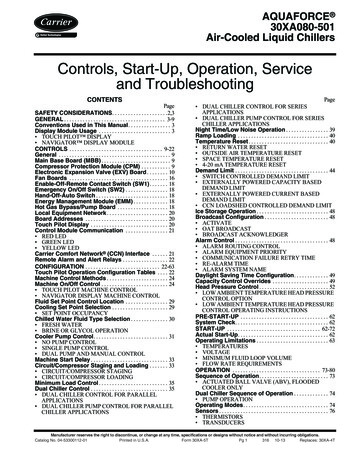
LCD with top polarizer removed from device and placed on top, such that the top andbottom polarizers are parallel.The optical effect of a twisted nematic device in the voltage-on state is far less dependenton variations in the device thickness than that in the voltage-off state. Because of this, thesedevices are usually operated between crossed polarizers such that they appear bright withno voltage (the eye is much more sensitive to variations in the dark state than the brightstate). These devices can also be operated between parallel polarizers, in which case thebright and dark states are reversed. The voltage-off dark state in this configuration appearsblotchy, however, because of small variations of thickness across the device.Both the liquid crystal material and the alignment layer material contain ionic compounds.If an electric field of one particular polarity is applied for a long period of time, this ionicmaterial is attracted to the surfaces and degrades the device performance. This is avoidedeither by applying an alternating current or by reversing the polarity of the electric field asthe device is addressed (the response of the liquid crystal layer is identical, regardless ofthe polarity of the applied field).Displays for a small number of individual digits and/or fixed symbols (as in digitalwatches, pocket calculators etc.) can be implemented with independent electrodes for eachsegment. In contrast full alphanumeric and/or variable graphics displays are usuallyimplemented with pixels arranged as a matrix consisting of electrically connected rows onone side of the LC layer and columns on the other side which makes it possible to addresseach pixel at the intersections. The general method of matrix addressing consists ofsequentially addressing one side of the matrix, for example by selecting the rows one-byone and applying the picture information on the other side at the columns row-by-row.For details on the various matrix addressing schemes see Passive-matrix and active-matrixaddressed LCDs.[edit] Brief history 1888: Friedrich Reinitzer (1858–1927) discovers the liquid crystalline nature ofcholesterol extracted from carrots (that is, two melting points and generation ofcolors) and published his findings at a meeting of the Vienna Chemical Society onMay 3, 1888 (F. Reinitzer: Beiträge zur Kenntniss des Cholesterins, Monatsheftefür Chemie (Wien) 9, 421-441 (1888)).[2]
1904: Otto Lehmann publishes his work "Flüssige Kristalle" (Liquid Crystals). 1911: Charles Mauguin first experiments of liquids crystals confined betweenplates in thin layers. 1922: Georges Friedel describes the structure and properties of liquid crystals andclassified them in 3 types (nematics, smectics and cholesterics). 1927: Vsevolod Frederiks devises the electrically switched light valve, called theFréedericksz transition, the essential effect of all LCD technology. 1936: The Marconi Wireless Telegraph company patents the first practicalapplication of the technology, "The Liquid Crystal Light Valve". 1962: The first major English language publication on the subject "MolecularStructure and Properties of Liquid Crystals", by Dr. George W. Gray.[3] 1962: Richard Williams of RCA found that liquid crystals had some interestingelectro-optic characteristics and he realized an electro-optical effect by generatingstripe-patterns in a thin layer of liquid crystal material by the application of avoltage. This effect is based on an electro-hydrodynamic instability forming what isnow called “Williams domains” inside the liquid crystal.[4] 1964: George H. Heilmeier, then working in the RCA laboratories on the effectdiscovered by Williams achieved the switching of colors by field-inducedrealignment of dichroic dyes in a homeotropically oriented liquid crystal. Practicalproblems with this new electro-optical effect made Heilmeier continue to work onscattering effects in liquid crystals and finally the achievement of the firstoperational liquid crystal display based on what he called the dynamic scatteringmode (DSM). Application of a voltage to a DSM display switches the initially cleartransparent liquid crystal layer into a milky turbid state. DSM displays could beoperated in transmissive and in reflective mode but they required a considerablecurrent to flow for their operation.[5][6][7] George H. Heilmeier was inducted in theNational Inventors Hall of Fame and credited with the invention of LCD.[8]Heilmeier's work is an IEEE Milestone.[9] 1960s: Pioneering work on liquid crystals was undertaken in the late 1960s by theUK's Royal Radar Establishment at Malvern, England. The team at RRE supportedongoing work by George Gray and his team at the University of Hull whoultimately discovered the cyanobiphenyl liquid crystals (which had correct stabilityand temperature properties for application in LCDs). 1970: On December 4, 1970, the twisted nematic field effect in liquid crystals wasfiled for patent by Hoffmann-LaRoche in Switzerland, (Swiss patent No. 532 261)with Wolfgang Helfrich and Martin Schadt (then working for the Central ResearchLaboratories) listed as inventors.[5] Hoffmann-La Roche then licensed the invention
to the Swiss manufacturer Brown, Boveri & Cie who produced displays for wristwatches during the 1970s and also to Japanese electronics industry which soonproduced the first digital quartz wrist watches with TN-LCDs and numerous otherproducts. James Fergason while working with Sardari Arora and Alfred Saupe atKent State University Liquid Crystal Institute filed an identical patent in the USAon April 22, 1971.[10] In 1971 the company of Fergason ILIXCO (now LXDIncorporated) produced the first LCDs based on the TN-effect, which soonsuperseded the poor-quality DSM types due to improvements of lower operatingvoltages and lower power consumption. 1972: The first active-matrix liquid crystal display panel was produced in theUnited States by Westinghouse, in Pittsburgh, PA.[11] 1983: Researchers at Brown, Boveri & Cie (BBC), Switzerland, invent the supertwisted nematic (STN) structure for passive-matrix addressed LCDs. H. Amstutz etal. were listed as inventors in the corresponding patent applications filed inSwitzerland on July 7, 1983, and October 28, 1983. Patents were granted inSwitzerland CH 665491, Europe EP 0131216,[12] US 4634229 and many morecountries. Scientific details are published in the referenced article.[13] 1990: Under different titles inventors conceived electrooptical effects asalternatives to twisted nematic field effect LCDs (TN- and STN- LCDs). Oneapproach was to use interdigital electrodes on one glass substrate only to producean electric field essentially parallel to the glass substrates (Abstract)[14]. To take fulladvantage of the properties of this In-Plane Switching (IPS) technology furtherwork was needed. After thorough analysis, details of advantageous embodimentsare filed in Germany by Guenter Baur et al and patented in various countries(Abstract)[15]. The Fraunhofer Institute in Freiburg, where the inventors worked,assigns these patents to Merck KGaA, Darmstadt, the world's leading supplier ofLC substances. 1992: Shortly thereafter, engineers at Hitachi work out various practical details ofthe IPS technology to interconnect the thin-film transistor array as a matrix and toavoid undesirable stray fields in between pixels (Abstract)[16]. Hitachi also improvesthe viewing angle dependance further by optimizing the shape of the electrodes(Super IPS). NEC and Hitachi become early manufacturers of active-matrix addressed LCDsbased on the IPS technology. This is a milestone for implementing large-screenLCDs having acceptable visual performance for flat-panel PC monitors and TVs. 1996 Samsung develops the optical patterning technique that enables multi-domainLCD. Multi-domain and In Plane Switching subsequently remain the dominantLCD designs through 2010.[17]
2007: In the 4Q of 2007 for the first time LCD televisions surpass CRT units inworldwide sales.[18] 2008: LCD TVs become the majority with a 50% market share of the 200 millionTVs forecast to ship globally in 2008 according to Display Bank.[19]A detailed description of the origins and the complex history of liquid crystal displays fromthe perspective of an insider during the early days has been published by Joseph A.Castellano in Liquid Gold: The Story of Liquid Crystal Displays and the Creation of anIndustry.[20] Another report on the origins and history of LCD from a different perspectiveuntil 1991 has been published by Hiroshi Kawamoto, available at the IEEE History Center.[21][edit] IlluminationAs LCD panels produce no light of their own, they require an external lighting mechanismto be easily visible. On most displays, this consists of a cold cathode fluorescent lamp thatis situated behind the LCD panel. Passive-matrix displays are usually not backlit, butactive-matrix displays almost always are, with a few exceptions such as the display in theoriginal Gameboy Advance.Recently, two types of LED backlit displays have appeared in some televisions as analternative to conventional backlit LCDs. In one scheme, the LEDs are used to backlightthe entire LCD panel. In another scheme, a set of red, green and blue LEDs is used toilluminate a small cluster of pixels, which can improve contrast and black level in somesituations. For example, the LEDs in one section of the screen can be dimmed to produce adark section of the image while the LEDs in another section are kept bright. Both schemesalso allows for a slimmer panel than on conventional displays.[edit] Passive-matrix and active-matrix addressed LCDsThis section does not cite any references or sources. Please help improve thissection by adding citations to reliable sources. Unsourced material may bechallenged and removed. (June 2009)
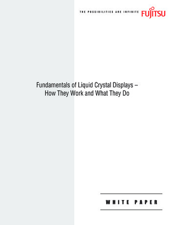
A general purpose alphanumeric LCD, with two lines of 16 characters.Monochrome passive-matrix LCDs were standard in most early laptops (although a fewused plasma displays) and the original Nintendo Game Boy[22] until the mid-1990s, whencolor active-matrix became standard on all laptops. The commercially unsuccessfulMacintosh Portable (released in 1989) was one of the first to use an active-matrix display(though still monochrome).Passive-matrix LCDs are still used today for applications less demanding than laptops andTVs. In particular, portable devices with less information content to be displayed, wherelowest power consumption (no backlight), low cost and/or readability in direct sunlight areneeded, use this type of display.Displays having a passive-matrix structure are employing super-twisted nematic STN ordouble-layer STN (DSTN) technology (the latter of which addresses a color-shiftingproblem with the former), and color-STN (CSTN) in which color is added by using aninternal filter.STN LCDs have been optimized for passive-matrix addressing. They exhibit a sharperthreshold of the contrast-vs-voltage characteristic than the original TN LCDs. This isimportant because pixels are subjected to partial voltages even while not selected.Crosstalk between activated and non-activated pixels has to be handled properly bykeeping the RMS voltage of non-activated pixels below the threshold voltage,[23] whileactivated pixels are subjected to voltages above threshold.[24] STN LCDs have to becontinuously refreshed by alternating pulsed voltages of one polarity during one frame andpulses of opposite polarity during the next frame. Individual pixels are addressed by thecorresponding row and column circuits. This type of display is called passive-matrixaddressed because the pixel must retain its state between refreshes without the benefit of asteady electrical charge. As the number of pixels (and, correspondingly, columns and rows)increases, this type of display becomes less feasible. Slow response times and poor contrastare typical of passive-matrix addressed LCDs with too many pixels.New zero-power (bistable) LCDs do not require continuous refreshing. Rewriting is onlyrequired for picture information changes. Potentially, passive-matrix addressing can beused with these new devices, if their write/erase characteristics are suitable.High-resolution color displays such as modern LCD computer monitors and televisions usean active matrix structure. A matrix of thin-film transistors (TFTs) is added to theelectrodes in contact with the LC layer. Each pixel has its own dedicated transistor,allowing each column line to access one pixel. When a row line is selected, all of thecolumn lines are connected to a row of pixels and voltages corresponding to the pictureinformation are driven onto all of the column lines. The row line is then deactivated and thenext row line is selected. All of the row lines are selected in sequence during a refreshoperation. Active-matrix addressed displays look "brighter" and "sharper" than passivematrix addressed displays of the same size, and generally have quicker response times,producing much better images.
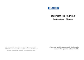
[edit] Active matrix technologiesA Casio 1.8 in color TFT LCD which equips the Sony Cyber-shot DSC-P93A digitalcompact camerasMain articles: Thin film transistor liquid crystal display and Active-matrix liquid crystaldisplay[edit] Twisted nematic (TN)See also: twisted nematic field effectTwisted nematic displays contain liquid crystals which twist and untwist at varying degreesto allow light to pass through. When no voltage is applied to a TN liquid crystal cell,polarized light passes through the 90-degrees twisted LC layer. In proportion to the voltageapplied, the liquid crystals untwist changing the polarization and blocking the light's path.By properly adjusting the level of the voltage almost any grey level or transmission can beachieved.[edit] In-plane switching (IPS)In-plane switching is an LCD technology which aligns the liquid crystals in a plane parallelto the glass substrates. In this method, the electrical field is applied through oppositeelectrodes on the same glass substrate, so that the liquid crystals can be reoriented(switched) in the same plane. This requires two transistors for each pixel instead of thesingle transistor needed for a standard thin-film transistor (TFT) display. Before LGEnhanced IPS was introduced in 2009, the additional transistors resulted in blocking moretransmission area, thus requiring a brighter backlight, which consumed more power, andmade this type of display less desirable for notebook computers. This newer, lower powertechnology can be found in the Apple iMac, iPad, and iPhone 4, the Hewlett-PackardEliteBook mobile workstations and the Nokia 701. Currently Panasonic is using anenhanced version eIPS for their large size LCD-TV products as well as Hewlett-Packard inits WebOS based TouchPad tablet.IPS LCD vs Amoled
LG claimed the smartphone LG Optimus Black with an IPS LCD (LCD NOVA) has thebrightness up to 700 nits, while the competitor has only IPS LCD with 518 nits and tumblean Amoled display with 305 nits. LG also claimed about the NOVA display which 50percent more efficient than regular LCD and consumes only 50 percent of Amoledconsumes when producing white on screen.[25] But, when it comes to contrast ratio, Amoleddisplay still performs best due to its underlying technology where the black levels aredisplayed as pitch black and not as dark grey. On the 24th of August 2011, Nokiaannounced the Nokia 701 and also made the claim of the world's brightest display at 1000nits. The screen also had Nokia's Clearblack layer which improved the contrast ratio,bringing it closer to that of the AMOLED screens.[edit] Advanced fringe field switching (AFFS)Known as fringe field switching (FFS) until 2003,[26] advanced fringe field switching issimilar to IPS or S-IPS offering superior performance and color gamut with highluminosity. AFFS was developed by Hydis Technologies Co., Ltd, Korea (formallyHyundai Electronics, LCD Task Force).[27]AFFS-applied notebook applications minimize color distortion while maintaining a widerviewing angle for a professional display. Color shift and deviation caused by light leakageis corrected by optimizing the white gamut which also enhances white/grey reproduction.In 2004, Hydis Technologies Co.,Ltd licensed AFFS to Japan's Hitachi Displays. Hitachi isusing AFFS to manufacture high-end panels. In 2006, HYDIS licensed AFFS to SanyoEpson Imaging Devices Corporation.Hydis introduced AFFS with improved outdoor readability in 2007. AFFS panels aremostly utilized in the cockpits of latest commercial aircraft displays.[edit] Vertical alignment (VA)Vertical alignment displays are a form of LCDs in which the liquid crystals naturally alignvertically to the glass substrates. When no voltage is applied, the liquid crystals remainperpendicular to the substrate creating a black display between crossed polarizers. Whenvoltage is applied, the liquid crystals shift to a tilted position allowing light to pass throughand create a gray-scale display depending on the amount of tilt generated by the electricfield.[edit] Blue Phase modeMain article: Blue Phase Mode LCDBlue phase mode LCDs have been shown as engineering samples early in 2008, but theyare not in mass-production yet. The physics of blue phase mode LCDs suggest that veryshort switching times ( 1 ms) can be achieved, so time sequential color control can
possibly be realized and expensive color filters would be obsolete. For details refer to BluePhase Mode LCD.[edit] Quality controlSome LCD panels have defective transistors, causing permanently lit or unlit pixels whichare commonly referred to as stuck pixels or dead pixels respectively. Unlike integratedcircuits (ICs), LCD panels with a few defective transistors are usually still usable. It isclaimed that it is economically prohibitive to discard a panel with just a few defectivepixels because LCD panels are much larger than ICs, but this has never been proven.[citationneeded]Manufacturers' policies for the acceptable number of defective pixels vary greatly. Atone point, Samsung held a zero-tolerance policy for LCD monitors sold in Korea.[28] As of2005, though, Samsung adheres to the less restrictive ISO 13406-2 standard.[29] Othercompanies have been known to tolerate as many as 11 dead pixels in their policies.[30] Deadpixel policies are often hotly debated between manufacturers and customers. To regulatethe acceptability of defects and to protect the end user, ISO released the ISO 13406-2standard.[31] However, not every LCD manufacturer conforms to the ISO standard and theISO standard is quite often interpreted in different ways.LCD panels are more likely to have defects than most ICs due to their larger size. Forexample, a 300 mm SVGA LCD has 8 defects and a 150 mm wafer has only 3 defects.However, 134 of the 137 dies on the wafer will be acceptable, whereas rejection of theLCD panel would be a 0% yield. In recent years, quality control has been improved. AnSVGA LCD panel with 4 defective pixels is usually considered defective and customerscan request an exchange for a new one.[according to whom?] Some manufacturers, notably in SouthKorea where some of the largest LCD panel manufacturers, such as LG, are located, nowhave "zero defective pixel guarantee", which is an extra screening process which can thendetermine "A" and "B" grade panels.[original research?] Many manufacturers would replace aproduct even with one defective pixel. Even where such guarantees do not exist, thelocation of defective pixels is important. A display with only a few defective pixels may beunacceptable if the defective pixels are near each other.LCD panels also have defects known as clouding (or less commonly mura), whichdescribes the uneven patches of changes in luminance. It is most visible in dark or blackareas of displayed scenes.[32][edit] Zero-power (bistable) displaysSee also: Ferro Liquid DisplayThe zenithal bistable device (ZBD), developed by QinetiQ (formerly DERA), can retain animage without power. The crystals may exist in one of two stable orientations ("Black" and"White") and power is only required to change the image. ZBD Displays is a spin-offcompany from QinetiQ who manufacture both grayscale and color ZBD devices.
Kent Displays has also developed a "no power" display that uses Polymer StabilizedCholesteric liquid crystal (ChLCD). A major drawback of ChLCD screens are their slowrefresh rate, especially at low temperatures[citation needed]. Kent has recently demonstrated theuse of a ChLCD to cover the entire surface of a mobile phone, allowing it to change colors,and keep that color even when power is cut off.[33]In 2004 researchers at the University of Oxford demonstrated two new types of zero-powerbistable LCDs based on Zenithal bistable techniques.[34]Several bistable technologies, like the 360 BTN and the bistable cholesteric, dependmainly on the bulk properties of the liquid crystal (LC) and use standard strong anchoring,with alignment films and LC mixtures similar to the traditional monostable materials.Other bistable technologies (i.e. Binem Technology) are based mainly on the surfaceproperties and need specific weak anchoring materials.[edit] SpecificationsImportant factors to consider when evaluating a Liquid Crystal Display (LCD): Resolution versus Range: Fundamentally resolution is the granularity (or number oflevels) with which a performance feature of the display is divided. Resolution isoften confused with range or the total end-to-end output of the display. Each of themajor features of a display has both a resolution and a range that are tied to eachother but very different. Frequently the range is an inherent limitation of the displaywhile the resolution is a function of the electronics that make the display work. Spatial Performance LCDs come in only one size for a variety of applications and avariety of resolutions within each of those applications. LCD spatial performance isalso sometimes described in terms of a “dot pitch”. The size (or spatial range) of anLCD is always described in terms of the diagonal distance from one corner to itsopposite. This is a historical aspect from the early days of CRT TV when CRTscreens were manufactured on the bottoms of a glass bottle. The diameter of thebottle determined the size of the screen. Later, when TVs went to a more squareformat, the square screens were measured diagonally to compare with the olderround screens.[35]The spatial resolution of an LCD is expressed in terms of the number of columns and rowsof pixels (e.g., 1024 768). This had been one of the few features of LCD performance thatwas easily understood and not subject to interpretation. Each pixel is usually composed of ared, green, and blue sub pixel. However there are newer schemes to share sub-pixelsamong pixels and to add additional colors of sub-pixels. So going forward, spatialresolution may be more subject to interpretation.One external factor to consider in evaluating display resolution is the resolution of yourown eyes. For a normal person with 20/20 vision, the resolution of your eyes is about oneminute of arc. In practical terms that means for an older standard definition TV set the ideal
viewing distance was about 8 times the height (not diagonal) of the screen away. At thatdistance the individual rows of pixels merge into a solid. If you were closer to the screenthan that, you would be able to see the individual rows of pixels. If you are further away,the image of the rows of pixels still merge, but the total image becomes smaller as you getfurther away. For an HDTV set with slightly more than twice the number of rows of pixels,the ideal viewing distance is about half what it is for a standard definition set. The higherthe resolution, the closer you can sit to the set or the larger the set can usefully be sitting atthe same distance as an older standard definition display.For a computer monitor or some other LCD that is being viewed from a very closedistance, resolution is often expressed in terms of dot pitch or pixels per inch. This isconsistent with the printing industry (another form of a display). Magazines, and otherpremium printed media are often at 300 dots per inch. As with the distance discussionabove, this provides a very solid looking and detailed image. LCDs, particularly on mobiledevices, are frequently much less than this as the higher the dot pitch, the more opticallyinefficient the display and the more power it burns. Running the LCD is frequently half, ormore, of the power consumed by a mobile device.An additional consideration in spatial performance are viewing cone and aspect ratio. TheAspect ratio is the ratio of the width to the height (for example, 4:3, 5:4, 16:9 or 16:10).Older, standard definition TVs were 4:3. Newer, HDTV’s are 16:9 as are most newnotebook computers. Movies are often filmed in much different (wider) aspect ratios whichis why there will frequently still be black bars at the top and bottom of a HDTV screen.The Viewing Angle of an LCD may be important depending on its use or location. Theviewing angle is usually measured as the angle where the contrast of the LCD falls below10:1. At this point, the colors usually start to change and can even invert, red becominggreen and so forth. Viewing angles for LCDs used to be very restrictive however, improvedoptical films have been developed that give almost 180 degree viewing angles from left toright. Top to bottom viewing angles may still be restrictive, by design, as looking at anLCD from an extreme up or down angle is not a common usage model and these photonsare wasted. Manufacturers commonly focus the light in a left to right plane to obtain abrighter image here. Temporal/Timing Performance: Contrary to spatial performance, temporalperformance is a
A liquid crystal display(LCD) is a flat panel display, electronic visual display, video display that uses the light modulating properties of liquid crystals (LCs). LCs do not emit light directly. They are used in a wide range of applications, including computer monitors, television, instrument panels, aircraft cockpit displays, signage, etc.