Transcription
YELLOW JACKET Refrigeration System AnalyzerUsers ManualUPC# 40812, 40813 and 40815(Versions 1.06 and higher)Note: These instructions do not cover the manifoldattached to the instrument.
Table of re You Start3Features and Specifications15Contact and Safety Information3Instrumentation Specifications16Getting Acquainted4Warranty Policy16Turning the Instrument Onand Off4Battery Considerations4Keyboard Keys5Understanding the Displays6Using the Temperature andVacuum Sensors7Getting the Job Done7Temperature and Pressure Mode7List of TablesTableTitlePg.1-1Safety Information31-2Symbols42-1Key Functions56-1Spare Parts14List of FiguresVacuum Mode9Vacuum Sensor Calibration10TableData Logging102-1Menu Display4Begin Logging102-2Battery Power Symbol5Playback and USB Functionality112-3Low Battery Pop-up Message5Erase Files112-4Menu Display6Settings112-5System Analyzer Display6Refrigerant Type112-6P/T Chart Display6Temperature Unit122-7Vacuum Gauge Display6Elevation122-8Data Logging Start-up Display6Auto Vacuum Gauge122-9Set-Up Display6Power Saving Mode122-10Sensor Connections7Auto Power Off122-11Sensors without Boots7Battery Type122-12Sensors with Boots7Graph Type123-1First System Analyzer Display8Time Format123-22nd System Analyzer Display8Time and Date123-33rd System Analyzer Display9Refrigerant Favorites123-4Vacuum Gauge Display9Zero Pressure133-5Sensor Calibration Number10Exiting the Set-Up Display134-1Data Logging Menu10Settings Shortcut134-2Data Logging Start-Up Screen10Maintenance134-3Data Log Files11General Maintenance135-1 (a, b)Set-up Displays11Replacing the Batteries145-2Time & Date Setting Screen12Spare Parts145-3Refrigerant Favorites Set-up12Software Updates145-4Refrigerant Favorites Screen13Further Assistance155-5Settings Shortcut13Specifications155-6Battery Access14Safety155-7Battery Servicing14TitlePg.
Chapter 1Before You StartContacting RitchieTo order accessories, receive assistance, orlocate the nearest YELLOW JACKET distributor.Corporate Office and Mailing Address:Table 1-1. Safety InformationWarning The instrument contains no internal user-serviceable parts other than batteries thatmay be accessed through the battery door.Do not open the instrument other than opening the battery door. Have the instrumentserviced only by Ritchie Engineering Co. orauthorized service centers.Ritchie Engineering Co, Inc.YELLOW JACKET Products Division10950 Hampshire Avenue SouthBloomington, MN 55438-2623 U.S.A.Phone: (952) 943-1300 or (800) 769-8370Fax: (800) 769-8370E-mail: custserv@yellowjacket.comwww.yellowjacket.com Do not use the instrument if it operates ab-Safety Information Do not operate the instrument or service bat-Use the instrument only as specified in thismanual. Otherwise, the protection provided bythe instrument may be impaired. Refer to safetyinformation in Table 1-1. Various refrigerants have been intentionallyA Warning identifies conditions and actions thatpose hazards to the user. A Caution identifiesconditions and actions that may damage theinstrument or the equipment under test. The refrigerant database in this unit mayTable 1-1. Safety InformationWarningTo avoid personal injury or death, follow theseguidelines: Most governments and legal authorities re-quire that HVAC technicians be trained andcertified in the safe and proper operation ofHVAC tools, such as this instrument. Sincethis tool may be connected to many types ofequipment through a limitless combinationof hoses and fittings, proper training is themost important element of using this toolsafely. Read the entire Users Manual before usingthe instrument. Use the instrument only as described in theUsers Manual, otherwise the protection provided by the equipment may be impaired. Do not use the instrument if it is damaged.Before you use the instrument, inspect thecase. Look for cracks or loose components.normally. Protection may be impaired. Whenin doubt, have the instrument serviced. Refer to warnings supplied with batteriesacquired for use in this instrument. If the batteries are not supplied with warnings, obtainthem from the manufacturer or supplier.teries around explosive gas, vapor, or dust.excluded for very significant safety reasons.Never use refrigerants in this instrument thatare not listed in the Set-up menu.include refrigerants classified as flammable.If such refrigerants are selected, the operatormay need additional certifications and/ortraining. Consult your government and legalauthority and comply fully with all requirements. Always wear eye and skin protection whenworking with refrigerants. Escaping refrigerant vapors will present a freezing danger.Do not direct refrigerant vapors venting fromhoses towards the skin. Maximum Working Pressure: High Side: 700psia (4.83 MPa) Maximum Working Pressure: Low Side: 350psia (2.41 MPa) Because this instrument allows for variousinputs including electrical and mechanical,care must be taken to observe any ways thatan electrical shock hazard could develop.Example: Wet or humid conditions, alongwith a damaged thermocouple or vacuumsensor, could allow an electrical path acrossthe instrument and over wet hoses. Keep allinterconnected equipment clean, organized,and in proper condition. Do not use the instrument if you are not qualified to recognizepotential electrical faults.cont. next page.3
Table 1-1. Safety InformationCautionTo avoid damage to equipment, follow theseguidelines: Do not allow pressures beyond the specifications listed in this manual. Be aware that internal pressures canchange unintentionally when equipment isstored with pressure in the system duringtemperature changes. If sub-cooled liquidrefrigerant is trapped in a hose or manifoldwith no room for expansion, it may result indramatic pressure variations with seeminglysmall temperature changes. Pressures canreach high enough levels to cause damage to the instrument’s internal pressuretransducers. Release liquid refrigerant fromthe hoses and manifold when disconnectingfrom a system. Refer to cautions supplied with batteriesacquired for use in this instrument. Do not attempt to introduce liquid orsamples heavily laden with oil into theinstrument. Read and observe instructions and specifications related to the batteries used in thisinstrument that may cause damage to it.Chapter 2Getting AcquaintedIntroductionThis instrument will clearly and accurately reportcritical information needed to properly service refrigeration and air-conditioning equipment. With itsmany features, time can be saved and the qualityof service can be verified through data reports forcustomer satisfaction. Some of the most significant features include: High accuracy and resolution Very fast and sensitive leak detection Robust temperature compensation with faultdetection Data logging and downloading for reporting andanalysis High durability and weather-resistanceNote that these instructions do not cover themanifold attached to the instrument.Turning the Instrument Onand OffPress and release thekey to turn unit on. Afterthe logo appears briefly, the instrument will present the main menu.Press and hold theunit off.key ( two seconds) to turn Do not use this instrument on systemscontaining leak sealing chemicals. Theseleak sealants can collect and harden in theinstrument, causing permanent damage.Table 1-2 SymbolsImportant informationPower On/OffT1Temperature 1T2Temperature 2RECIndicates that the instrument isrecording readings (data logging) Indicates page-by-page scrollingmode (during data log playback)BatteryBattery connector orientation4Figure 2-1. Menu DisplayBattery ConsiderationsThe instrument uses eight AA batteries. Theuser may select batteries of the following types:Alkaline, AA-Lithium, Ni-MH, Ni-Cd, Li-Pol, Li-Ionfrom the Setup menu (see Chapter 5). Do not mixbattery types, including rating (i.e., do not mix fourNi-MH rated at 1600mAh with four Ni-MH ratedat 1800mAh). Also, each battery in a set of eightmust be at the same power state, preferably fullycharged. The battery life indicator is only accuratewhen the correct battery type is selected in theSET-UP menu.
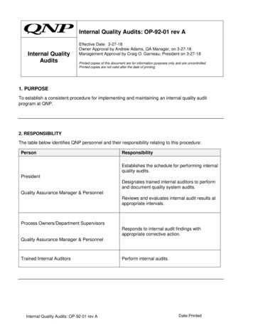
The illustration below shows three bars that indicate a fresh or well-charged battery pack. Whenthe battery weakens, the bars will disappear oneby-one as the battery power decays. When onebar remains, the symbol will turn yellow. When allbars are gone, the batteries are nearly dead andthe symbol will turn red. The unit will briefly showa pop-up message just before the unit stores alldata and then automatically shuts off.Maximizing Battery LifeBattery life decays fastest when the DIGITALMANIFOLD display is selected, the vacuum sensor is attached, and the backlight is on. Batterylife during data logging is maximized by usinghigh-performance batteries, detaching the vacuumsensor (if not in use), and a short Power SavingMode time setting is selected.Keyboard KeysFigure 2-2. Battery Power SymbolNote that pressing a key that has not beenassigned to a function will result in three, shortbeeps.Table 2-1. Key FunctionsPower On/Off (see Chapter 2, Turning the Instrument On and Off).MenuAccesses menu of instrumentfunctions.EnterAccepts selected functions andvalues.This key will also toggle the instrument data display modes. SeeChapter 3.Figure 2-3. Low Battery Pop-Up MessageDuring playback of logged data,toggles between point-by-point andpage-by-page scrolling.Automatic Power OffThe instrument may automatically turn off aftera period of time. The default is one hour. Theuser may select other settings from ten minutesto four hours from the Setup menu (see Chapter5). The user may also disable this feature. TheAuto Power Off time limit is automatically disabledduring data logging and is automatically restoredonce data logging has terminated.ClearPower Saving ModeHoldFreezes the data display at themoment the key is depressed whendata is being displayed. A secondkey press will return the display tothe normal, dynamic mode (not accessible during data logging).ChartTimeToggles time resolution to displaymore or less of the data acquisitionevent, enhancing a user’s ability tosee significant events (not accessibleduring data logging).ChartPressureToggles pressure resolution to fitanalog pressure data within thedisplay, enhancing a user’s ability tosee significant events.Up/LeftAssists in selection of values anddata points depending on the function feature involved (not accessibleduring data logging).The display backlight will fade, darkening thedisplay to save battery life if a key has not beenpressed for a set period of time. While in PowerSaving Mode, pressing any key turns the displaybacklight back to full brightness. Note thatbacklighting is independent from the displaybrightness and contrast settings (see Chapter 5)which do not affect battery life.The Power Saving Mode is preset to 10 minutes.From the Setup menu (see Chapter 5), you canspecify settings from 30 seconds to 60 minutes.Low Battery ConditionsThe unit will attempt to store all logged data iflow battery power is detected. Once the data isstored, unit will turn off.A single press clears the chart setpoint. (See Figure 3-1, item 11)Press and hold to clear ‘Min.’ and‘Max.’ values. (See Figure 3-1,item 5)Resets vacuum timer to 0:00:00.(See Chapter 3)Down/Right5
Understanding the DisplaysFigure 2-4. Menu DisplayUse the or keys to scroll through the menu.Figure 2-7. Vacuum Gauge Display(See Chapter 3)Press the “Enter” key to make a selection.Figure 2-5. System Analyzer Display(See Chapter 3)Figure 2-6. P/T Chart DisplayThis display shows the “P/T” (Pressure/Temperature) chart for the refrigerant that is selected in the“Set-Up” display. Use the or keys to scrollthrough the chart. Press the “Menu” key to exit.6Figure 2-8. Data LoggingStart-Up Display(See Chapter 4)Figure 2-9. Set-Up Display(See Chapter 5)
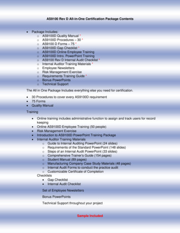
Using the Temperature andVacuum SensorsChapter 3Getting the Job DoneTo use the external temperature and vacuum sensors, plug them into the connectors located on theside of the instrument. The use of rubber connector boots is optional. They will, however, increasethe weather resistance of the unit and reduce theamount of dust that could enter at the vacuumconnector, if that boot isn’t used. When not in use,the vacuum and USB connector openings shouldbe covered with the tethered plugs.Temperature andPressure ModeNote: A common mistake is to forget to zero thepressure sensors before using the instrument fora job, resulting in incorrect pressure readings andcalculations. See Chapter 5 - Settings, Zero pressure, for more information.The unit will simultaneously display inputs fromfour sources: T1 Temperature Sensor (Suction linetemperature for superheat) T2 Temperature Sensor (Liquid linetemperature for subcooling) Low Side Pressure Transducer (internal) High Side Pressure Transducer (internal)T1T2Vacuum(Plugged)USB(Plugged)Figure 2-10. Sensor ConnectionsTemperature Probes – The system analyzer willdisplay readings from any K-type thermocoupleprobe with a miniature styleconnector (see picture). TheK-type is usually indicatedwith a letter K on the connector. The miniature stylethermocouple connectorshave two flat blade contacts. The two blade contacts are different widths to ensure proper polarity.Plug the blade contacts into the matching slots inthe analyzer.Your system analyzer includes a pair of K-typeclamp probes for easy pipe temperature measurement.Figures 3-1, 3-2, and 3-3 show the three digitalmanifold displays for monitoring system chargingand operation.Figure 2-11. Sensors without Boots The first display (see Figure 3-1) presentsall available data outputs including XYTime-Pressure charting. The second display (see Figure 3-2) is thesame as the first except for the exclusion ofthe Temp-1, Temp-2, vapor (Low sat.) andliquid (High sat.) saturation points. The third display (see Figure 3-3) is the sameas the first except for the exclusion of the XYTime-Pressure charting.Once the default digital manifold display has beenselected from the main menu, pressing the “Enter”key will advance through all three displays.Figure 2-12. Sensors with Boots7
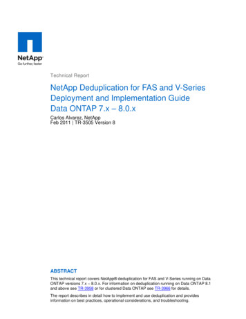
While using any of the digital manifold orvacuum gauge display screens, press theUP/LEFT key to activate a pop-up screenwhere options can be changed using theUP/LEFT and DOWN/RIGHT keys. Pressthe MENU key to save the selections andexit the pop-up screen.9Superheat: The calculated superheat forthe selected refrigerant.Subcool: The calculated subcooling forthe selected refrigerant.Figure 3-1. First SystemAnalyzer Display1Date and Time. (See Chapter 5 to set).2Pressure units. While using any of the digitalmanifold or vacuum gauge display screens,press the UP/LEFT key to activate a pop-upscreen where options can be changed usingthe UP/LEFT and DOWN/RIGHT keys.Press the MENU key to save the selectionsand exit the pop-up screen.3Refrigerant type. While using any of thedigital manifold or vacuum gauge displayscreens, press the UP/LEFT key to activatea pop-up screen where options can bechanged using the UP/LEFT and DOWN/RIGHT keys. Press the MENU key to savethe selections and exit the pop-up screen.4Battery strength. (See Chapter 2 for batteryconsiderations).5The minimum and maximum pressuresencountered since the memory was lastcleared. (“Clear” key - typical for high andlow sides).6Set: The pressure represented by the centerhorizontal line on both charts.NOTE: These calculations are basedon the measured pressures andtemperatures.10Charted pressure11Time indication (cursor)12Seconds per samples (sample interval).Use the “Chart Time” key to toggle thisvalue through the available settings.A small number will show rapid pressurechanges by displaying a short period oftime (‘zoom in’). A large number will showonly slower pressure changes by displaying a larger period of time (‘zoom out’).13Pressure scale range. Use the “ChartPres.” Key to toggle pressure resolutionto fit analog pressure data within thedisplay, enhancing a user’s ability to seesignificant events. A small range will showsmall pressure changes (‘zoom in’). Alarger range will show only larger pressure changes (‘zoom out’).14Left Side: Suction pressure (‘Low Side’)Right Side: Discharge pressure(‘High Side’)Crs: (Cursor) The charted pressure markedby the vertical line on both charts.7Left Side: Vapor Saturate. The vapor saturation temperature for the selected refrigerant.(Also known as dew point)Right Side: Liquid Saturate. The liquid saturation temperature for the selected refrigerant. (Also known as bubble point)8Temp-1 (T1): The temperature indicated bythe T1 thermocouple. (For proper superheatmeasurement, the T1 probe should be measuring the suction line temperature.)Temp-2 (T2): The temperature indicated bythe T2 thermocouple. (For proper subcooling measurement, the T2 probe should bemeasuring the liquid line temperature.)8Figure 3-2. 2nd System Analyzer Display
1Pressure units. While using any of thedigital manifold or vacuum gauge displayscreens, press the UP/LEFT key to activatea pop-up screen where options can bechanged using the UP/LEFT and DOWN/RIGHT keys. Press the MENU key to savethe selections and exit the pop-up screen.2Discharge pressure (‘High Side’).3When data recording is activated, thisindicator will gradually change from redto blue indicating the size of one page ofdata. During playback, it will help the userto decide whether to move through thedata slowly or page-by-page. Adjusting thesampling rate will affect the amount of dataon each page.4Vacuum reading. The message “Out ofrange” will appear until the vacuum reaches25,000 microns.5Elapsed time display. Press “Clear” to resetcounter to 0:00:00.6Vacuum Units. Vacuum readings can bedisplayed in Microns, mTorr, Torr, mmHg,mBar, KPa, and Pa.Figure 3-3. 3rd System Analyzer DisplayVacuum ModeNote: If you are using a new vacuum sensor forthe first time, the vacuum sensor calibration number must be entered. The instrument will reportincorrect data if this is not done. Go to ‘VacuumSensor Calibration Utility’ further down in thischapter for instructions.The instrument can simultaneously use displayinputs from two sources:If it is desirable to match the pressure unitswith the vacuum units, the pressure unitsmust be selected before proceeding withvacuum procedure. Vacuum Sensor Internal Pressure TransducersNote: Although the internal pressure transducersare primarily used for positive pressures, they alsogive a helpful indication of vacuum activity beforethe vacuum sensor indicates values in the rangesthat are typical when operating vacuum pumps.This screen can be accessed from the main menu,“Vacuum Gauge” selection, or the “Digital Manifold”screen by simply plugging in a vacuum sensor ifthe “Auto micron meter” is set to “ON”. (See “Settings - Auto Vacuum Gauge” in the Setup menu.)While using any of the digital manifold orvacuum gauge display screens, press theUP/LEFT key to activate a pop-up screenwhere options can be changed using theUP/LEFT and DOWN/RIGHT keys. Pressthe MENU key to save the selections andexit the pop-up screen.7When recording is activated, the samplingrate is displayed here. See “Chapter 4 –Data Logging” to set the sampling rate.8The minimum and maximum pressuresencountered since the memory was lastcleared (“Clear” key). (Typical for high andlow sides.)9Left Side: Suction pressure (‘Low Side’).Press the UP/LEFT key to activate a popup screen where options can be changedusing the UP/LEFT and DOWN/RIGHTkeys. Press the MENU key to save theselections and exit the pop-up screen.Figure 3-4. Vacuum Gauge Display9
Vacuum Sensor Calibration UtilityWhenever a new vacuum sensor is used, the sixdigit calibration number printed on the side of thevacuum sensor must be entered. At the screenshown in Figure 3-4, press and hold the “ENTER”key. A small pop-up window will appear wherethe elapsed time usually appears. The 6 digitnumber displayed is the sensor calibration numbe
2-3 Low Battery Pop-up Message 5 2-4 Menu Display 6 2-5 System Analyzer Display 6 2-6 P/T Chart Display 6 2-7 Vacuum Gauge Display 6 2-8 Data Logging Start-up Display 6 2-9 Set-Up Display 6 2-10 Sensor Connections