Transcription
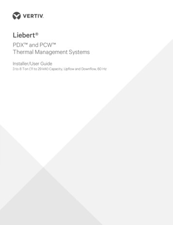
Liebert PDX and PCW Thermal Management SystemsInstaller/User Guide3 to 8 Ton (11 to 29 kW) Capacity, Upflow and Downflow, 60 Hz
The information contained in this document is subject to changewithout notice and may not be suitable for all applications. Whileevery precaution has been taken to ensure the accuracy andcompleteness of this document, Vertiv assumes no responsibilityand disclaims all liability for damages resulting from use of thisinformation or for any errors or omissions. Refer to other localpractices or building codes as applicable for the correct methods,tools, and materials to be used in performing procedures notspecifically described in this document.The products covered by this instruction manual are manufacturedand/or sold by Vertiv. This document is the property of Vertiv andcontains confidential and proprietary information owned by Vertiv.Any copying, use or disclosure of it without the written permissionof Vertiv is strictly prohibited.Names of companies and products are trademarks or registeredtrademarks of the respective companies. Any questions regardingusage of trademark names should be directed to the originalmanufacturer.Technical Support SiteIf you encounter any installation or operational issues with your product, check the pertinentsection of this manual to see if the issue can be resolved by following outlined procedures.Visit https://www.Vertiv.com/en-us/support/ for additional assistance.Vertiv Liebert PDX and PCW Installer/User Guide
TABLE OF CONTENTSImportant Safety Instructions11 Nomenclature and Components111.1 Liebert PDX Model-number Nomenclature121.2 Liebert PCW Model-number Nomenclature131.3 Component Location132 Pre-installation Preparation and Guidelines152.1 Planning Dimensions162.2 Considerations for Air Distribution162.3 Connections and System Setup172.4 Operating Conditions172.4.1 Cooling, Humidification and Dehumidification172.4.2 Heating182.5 Shipping Dimensions and Unit Weights183 Equipment Inspection and Handling213.1 Packaging Material223.2 Handling the Unit while Packaged223.3 Unpacking the Unit233.3.1 Removing the Unit from the Skid with a Forklift243.3.2 Removing the Unit from the Skid Using Rigging253.3.3 Moving the Unit with Piano Jacks273.4 Placing the Unit on a Floor Stand284 Piping and Refrigerant Requirements294.1 Fluid Piping for Air-cooled, Water/Glycol-cooled and Chilled-water Piping Applications304.1.1 Field-installed, Gravity-fed Drain Line Requirements314.1.2 Water Supply-line Requirements for the Optional Humidifier334.2 Refrigerant Piping and Charging344.2.1 Refrigerant Piping Guidelines for Air-cooled Systems354.2.2 Refrigerant Line Sizes and Equivalent Lengths364.2.3 Refrigerant Charge Requirements for Air-cooled Systems364.2.4 Evacuation, Leak-testing, and Charging Air-cooled Systems with TXVand without Receivers394.2.5 Evacuation, Leak-testing, and Charging Air-cooled Systems with Liebert Lee-Temp “Flooded-condenser” Head-pressure Control System444.2.6 Evacuation, Leak-testing and Charging Air-cooled Systemswith EEV and Unheated Receivers464.2.7 Superheat and Refrigerant Charge Optimization484.3 Water/Glycol and Chilled-water Loop Piping Guidelines504.3.1 Leak Checking for Unit and Field-installed Piping51i
5 Electrical Connections535.1 Wye- and Delta-connected Power Supply for PDX and PCW555.2 Supply Temperature Sensor565.3 Return Air Sensor565.3.1 Internal Temperature/Humidity Sensor565.3.2 Remote Temperature/Humidity Sensor565.4 2T Wired Remote Sensors566 Checklist for Completed Installation596.1 Moving and Placing Equipment596.2 Electrical Installation Checks596.3 Piping Installation Checks596.4 Other Installation Checks607 Initial Start-up Checks and Commissioning Procedure for Warranty Inspection618 Maintenance638.1 Filters648.1.1 Filter-replacement for Downflow Units648.1.2 Filter-replacement for Upflow Units658.1.3 Filter-replacement for Upflow Units with Rear Return658.2 Blower Drive System—EC Fans8.2.1 Fan Impellers and Bearings Maintenance678.2.2 Protective Features678.2.3 Fan Assembly Troubleshooting678.2.4 Replacing EC Fans in Downflow Models718.2.5 Replacing EC Fans in Upflow Models748.3 Infrared Humidifier Maintenance8.3.1 Cleaning Humidifier Pan and Float Switch8.3.2 Changing Humidifier Lamps8.4 Steam-generating Humidifier Maintenance787879808.4.1 Removing the Old Canister828.4.2 Mandatory Cleaning of the Drain Valve828.4.3 Installing the New Canister838.4.4 Humidifier Troubleshooting848.5 Condensate-drain and Condensate-pump System Maintenanceii66888.5.1 Condensate Drain888.5.2 Condensate Pump888.6 Air-Cooled Condenser and Drycooler Maintenance888.7 Electric Reheat Maintenance888.8 Thermostatic Expansion Valve (TXV) Maintenance898.8.1 Determining Suction Superheat898.8.2 Adjusting Superheat Setting with the TXV89Vertiv Liebert PDX and PCW Installer/User Guide
8.9 Electronic Expansion Valve (EEV) Maintenance898.10 Compressor Maintenance908.10.1 Compressor Oil908.10.2 Scroll and Digital-scroll Compressor Maintenance908.10.3 Replacement Compressors908.10.4 Rotalock Valve on Scroll and Digital-Scroll Compressors918.10.5 Unloading Solenoid(s) on a Digital-scroll Compressor918.10.6 Compressor Electrical Failure (Motor Burnout)928.10.7 Replacing a Compressor with Electrical Failure (Motor Burnout)928.10.8 Compressor Mechanical Failure938.10.9 Replacing a Compressor with Mechanical Failure938.11 Facility Fluid and Piping Maintenance for Water and Glycol Systems948.12 Glycol Solution Maintenance948.13 Motorized Ball Valve (MBV) Maintenance (Digital-scroll Compressors)948.13.1 MBV Control958.13.2 MBV Control Method958.13.3 MBV Adjustment958.13.4 MBV Start-up958.13.5 MBV Location958.13.6 MBV Manual Control958.14 Drycooler Aquastat Settings969 Preventive Maintenance Checklist97Appendices103Appendix A: Technical Support and Contacts103Appendix B: Liebert PDX Model-number Detail105Appendix C: Liebert PCW Model-number Detail108Appendix D: Submittal Drawings111iii
This page intentionally left blankivVertiv Liebert PDX and PCW Installer/User Guide
IMPORTANT SAFETY INSTRUCTIONSSAVE THESE INSTRUCTIONSThis manual contains important safety instructions that should be followed during the installation andmaintenance of the Liebert PDX/PCW. Read this manual thoroughly before attempting to install oroperate this unit.Only qualified personnel should move, install or service this equipment.Adhere to all warnings, cautions, notices and installation, operating and safety instructions on the unitand in this manual. Follow all installation, operation and maintenance instructions and all applicablenational and local building, electrical and plumbing codes.WARNING! Arc flash and electric shock hazard. Open all local and remote electric power-supplydisconnect switches, verify with a voltmeter that power is Off and wear appropriate,OSHA-approved personal protective equipment (PPE) per NFPA 70E before working within theelectric control enclosure. Failure to comply can cause serious injury or death. Customer mustprovide earth ground to unit, per NEC, CEC and local codes, as applicable. Before proceedingwith installation, read all instructions, verify that all the parts are included and check thenameplate to be sure the voltage matches available utility power. The Liebert controller doesnot isolate power from the unit, even in the “Unit Off” mode. Some internal components requireand receive power even during the “Unit Off” mode of the controller. The factory-supplieddisconnect switch is inside the unit. The line side of this switch contains live high-voltage. Theonly way to ensure that there is NO voltage inside the unit is to install and open a remotedisconnect switch. Refer to unit electrical schematic. Follow all local codes.WARNING! Risk of electric shock. Can cause equipment damage, injury or death. Open all localand remote electric power supply disconnect switches and verify with a voltmeter that power isoff before working within any electric connection enclosures. Service and maintenance workmust be performed only by properly trained and qualified personnel and in accordance withapplicable regulations and manufacturers’ specifications. Opening or removing the covers toany equipment may expose personnel to lethal voltages within the unit even when it isapparently not operating and the input wiring is disconnected from the electrical source.WARNING! Risk of electric shock. Can cause serious injury or death. The Liebert iCOMmicroprocessor does not isolate power from the unit, even in the "Unit Off" mode. Some internalcomponents require and receive power even during the "unit off" mode of the Liebert iCOMcontrol. Open all local and remote electric power disconnect switches and verify with avoltmeter that power is Off before working on any component of the system.Important Safety Instructions1
WARNING! Risk of electric shock. Can cause serious injury or death. Open all local and remoteelectric power supply disconnect switches and verify with a voltmeter that power is off beforeworking within the fan-motor electric-connection enclosures. Fan-motor controls can maintainan electric charge for 10 minutes after power is disconnected. Wait 10 minutes after power isverified as off before working within the electric control/connection enclosures. Use only fullytrained and qualified HVAC technicians to perform maintenance on the fans.WARNING! Risk of electric shock. Can cause injury or death. Open all local and remote electricpower-supply disconnect switches and verify that power is Off with a voltmeter before workingwithin the condensate pump electrical connection enclosure. The Liebert iCOM does notisolate power from the unit, even in the “Unit Off” mode. Some internal components require andreceive power even during the “Unit Off” mode of the Liebert iCOM.WARNING! Risk of electric shock. Can cause serious injury or death. The Liebert iCOMmicroprocessor does not isolate power from the unit, even in the "Unit Off" mode. Some internalcomponents require and receive power even during the "unit off" mode of the Liebert iCOMcontrol. Open all local and remote electric power disconnect switches and verify with avoltmeter that power is Off before working on any component of the system.WARNING! Risk of over-pressurization of the refrigeration system. Can cause explosivedischarge of high-pressure refrigerant, loss of refrigerant, environmental pollution, equipmentdamage, injury, or death. This unit contains fluids and gases under high pressure. Use extremecaution when charging the refrigerant system. Do not pressurize the system higher than thedesign pressure marked on the unit's nameplate. Relieve pressure before cutting into ormaking connections/disconnections to the piping system. Local building or plumbing codesmay require installing a fusible plug or other type of pressure-relief device in the system.WARNING! Risk of contact with high-speed rotating fan blades. Can cause serious injury ordeath. Open all local and remote electric power-supply disconnect switches, verify with avoltmeter that power is off, and verify that all fan blades have stopped rotating before workingin the unit cabinet or on the fan assembly. If control voltage is applied, the fan motor can restartwithout warning after a power failure. Do not operate the unit with any or all cabinet panelsremoved. Do not operate upflow units without installing a plenum, duct work or guard over theblower opening(s) on the top surface of the unit cabinet. Ductwork must be connected to theblower(s), or a plenum must be installed on the blower deck for protection from rotating blowerwheel(s) on upflow units.WARNING! Risk of top-heavy unit falling over. Improper handling can cause equipmentdamage, injury or death. Read all of the following instructions and verify that all lifting andmoving equipment is rated for the weight of the unit before attempting to move, lift, removepackaging from or prepare the unit for installation. Unit weights are specified in Table 2.3 onpage 19.2Vertiv Liebert PDX and PCW Installer/User Guide
WARNING! Risk of improper wiring, piping, moving, lifting and handling. Can cause equipmentdamage, serious injury or death. Installation and service of this equipment should be done onlyby qualified personnel who have been specially-trained in the installation of air-conditioningequipment and who are wearing appropriate, OSHA-approved PPE.WARNING! Risk of improper wire sizing/rating and loose electrical connections. Can causeoverheated wire and electrical connection terminals resulting in smoke, fire, equipment andbuilding damage, injury or death. Use correctly sized copper wire only and verify that allelectrical connections are tight before turning power On. Check all electrical connectionsperiodically and tighten as necessary.WARNING! Risk of very heavy fan module dropping downward suddenly. Can cause injury ordeath. Only properly trained and qualified personnel should work on this equipment. The fanmodule weighs approximately 100 lb. (45.4 kg).WARNING! Risk of improper humidifier-canister maintenance. Can cause smoke and fire,activation of fire suppression systems, building evacuation, dispatching of fire/rescueequipment and personnel, and catastrophic canister failure resulting in water leaks, equipmentdamage, injury, or death. Using a humidifier canister that has reached the end of it’s service lifecan be extremely hazardous. If the canister cannot be replaced immediately at the end of lifecondition, turn Off the power and water supply to the humidifier and remove the canister until areplacement canister can be installed. Do not ignore humidifier problem alarms. Resettinghumidifier without addressing cause may result in fire or damage due to leaking water. SeeTable 8.4 on page 85, for alarm corrective actions.WARNING! Risk of humidifier canister meltdown, smoke and fire. Can cause fire suppressionsystem activation, fire and smoke alarm activation, building evacuation, dispatching of fire andrescue equipment and personnel and water leaks resulting in expensive equipment or buildingdamage, injury or death. Check steam generating humidifier electrode plugs to ensure that theyare pressed firmly onto pins. Loose connections will cause overheating of cylinder and plugs.WARNING! Risk of explosive discharge of high-pressure refrigerant. Can cause serious injury.Neutral and service ports on the rotalock valve do not have a valve core. Front-seat the servicevalves and relieve pressure from the compressor before loosening a part or a componentattached to the service valve. Follow local codes to properly reclaim refrigerant.Important Safety Instructions3
CAUTION: Risk of excessive refrigerant line pressure. Can cause tubing and componentrupture resulting in equipment damage and personal injury. Do not close off any field-installedrefrigerant-line isolation valve for repairs unless a pressure-relief valve is field- installed in theline between the isolation valve and the check valve. The pressure-relief valve must be rated 5%to 10% higher than the system-design pressure. An increase in ambient temperature can causethe pressure of the isolated refrigerant to rise and exceed the system-design pressure rating(marked on the unit nameplate).CAUTION: Risk of improper moving, lifting and handling. Can cause equipment damage orinjury. Only properly trained and qualified personnel should work on this equipment.Evaporator fan modules weigh approximately 100 lb (45.4 kg). Use proper lifting techniques andwear appropriate, OSHA-approved PPE to avoid injury and dropping the fan module duringremoval. Equipment used in handling/lifting, and/or installing the fan assembly must meetOSHA requirements. Use handling/lifting equipment rated for the weight of the fan assembly.Use ladders rated for the weight of the fan assembly and technicians if used during installation.Refer to handling/lifting, and/or installation equipment operating manual for manufacturer'ssafety requirements and operating procedures.CAUTION: Risk of contact with sharp edges, splinters, and exposed fasteners. Can causeinjury. Only properly trained and qualified personnel wearing appropriate, OSHA-approved PPEshould attempt to move, lift, remove packaging from or prepare the unit for installation.CAUTION: Risk of contact with hot surfaces. Can cause injury. The electronics housing,humidifier components, compressor, refrigerant discharge lines, fan motor, and some electricalcomponents are extremely hot during unit operation. Allow sufficient time for them to cool to atouch-safe temperature before working within the unit cabinet. Use extreme caution and wearappropriate, OSHA-approved PPE when working on or near hot components.CAUTION: Risk of contact with extremely hot water and part surfaces. Can cause burn injury.The infrared humidifier bulbs, metal enclosure, humidifier water, water reservoir pan and draintubing are very hot during and shortly after operation. Allow sufficient time for these parts tocool to a touch-safe temperature before handling. Use extreme caution, and wear appropriate,OSHA-approved PPE when performing maintenance on the infrared humidifier.CAUTION: Risk of contact with hot surfaces. Can cause burn injury. The humidifier canisterand steam discharge lines are extremely hot during operation. Allow sufficient time for them tocool to a touch-safe temperature before handling. Use extreme caution and wear appropriate,OSHA-approved PPE when performing maintenance on the humidifier.4Vertiv Liebert PDX and PCW Installer/User Guide
CAUTION: Risk of handling heavy and lengthy parts. Can cause personal injury and equipmentdamage. Cabinet panels can exceed 5 ft. (1.5 m) in length and weigh more than 35 lb. (15.9 kg).Follow relevant OSHA lifting recommendations and consider using a two-person lift for safeand comfortable removal and installation of cabinet panels. Only properly trained and qualifiedpersonnel wearing appropriate, OSHA-approved PPE should attempt to remove or installcabinet panels.CAUTION: Risk of smoke generation. Can cause fire suppression and alarm system activation,resulting in injury during building evacuation and mobilization of emergency fire and rescueservices. Start-up operation of optional electric reheat elements can create smoke or fumesthat can activate the facility alarm and fire suppression system. Prepare and take appropriatesteps to manage this possibility. Activating reheat during initial start-up may burn offparticulates from electric reheat elements. Check the steam generating humidifier electrodeplugs to ensure that they are pressed firmly onto the pins. Loose connections will cause thecylinder and plugs to overheat. Before beginning initial start-up checks, make certain that unitwas installed according to the instructions in this manual. All exterior panels must be in place.CAUTION: Risk of exposure to harmful noise levels. Can cause hearing injury or loss.Depending on the installation and operating conditions, a sound pressure level greater than70 dB(A) may arise. Take appropriate technical safety measures. Operating personnel mustwear appropriate, OSHA-approved PPE and observe all appropriate hearing-protection safetyrequirements.NOTICERisk of improper power-supply connection. Can cause equipment damage and loss of warrantycoverage.Prior to connecting any equipment to a main or alternate power source (for example: back-upgenerator systems) for start-up, commissioning, testing, or normal operation, ensure that thesesources are correctly adjusted to the nameplate voltage and frequency of all equipment to beconnected. In general, power-source voltages should be stabilized and regulated to within 10% of the load nameplate nominal voltage. Also, ensure that no three-phase sources aresingle-phased at any time.NOTICERisk of oil contamination with water. Can cause equipment damage.Liebert PDX systems require the use of POE (polyolester) oil. POE oil absorbs water at a muchfaster rate when exposed to air than previously used oils. Because water is the enemy of areliable refrigeration system, extreme care must be used when opening systems duringinstallation or service. If water is absorbed into the POE oil, it will not be easily removed and willnot be removed through the normal evacuation process. If the oil is too wet, it may require an oilchange. POE oils also have a property that makes them act as a solvent in a refrigerationsystem. Maintaining system cleanliness is extremely important because the oil will tend tobring any foreign matter back to the compressor.Important Safety Instructions5
NOTICERisk of improper refrigerant charging. Can cause equipment damage.Refrigerant charge must be weighed into air-cooled compressorized systems before they arestarted. Starting scroll and digital scroll compressors without proper refrigerant charging cancause the compressors to operate at less than 5 F (–15 C) evaporator temperature and at lessthan 20 psig (138 kPa). Operation for extended periods at less than 20 psig (138 kPa) cancause premature compressor failure.NOTICERisk of clogged or leaking drain lines and leaking water-supply lines. Can cause equipment andbuilding damage.This unit requires a water drain connection. Drain lines must be inspected at start-up andperiodically, and maintenance must be performed to ensure that drain water runs freelythrough the drain system and that lines are clear and free of obstructions and in goodcondition with no visible sign of damage or leaks. This unit may also require an external watersupply to operate.Improper installation, application and service practices can result in water leakage from theunit. Water leakage can result in catastrophic and expensive building and equipment damageand loss of critical data center equipment.Do not locate unit directly above any equipment that could sustain water damage.We recommend installing a monitored fluid-detection system to immediately discover andreport coolant-fluid system and condensate drain-line leaks.6Vertiv Liebert PDX and PCW Installer/User Guide
NOTICERisk of piping-system corrosion and freezing fluids. Can cause leaks resulting in equipmentand expensive building damage. Cooling coils, heat exchangers and piping systems are at highrisk of freezing and premature corrosion. Fluids in these systems must contain an inhibitor toprevent premature corrosion.The system coolant fluid must be analyzed by a competent fluid-treatment specialist beforestart up to establish the inhibitor level and evaluated at regularly scheduled intervalsthroughout the life of the system to determine the pattern of inhibitor depletion. The fluidcomplexity and variations of required treatment programs make it extremely important toobtain the advice of a competent and experienced fluid-treatment specialist and follow aregularly scheduled coolant-fluid system-maintenance program.Fluid chemistry varies greatly as do the required additives, called inhibitors, that reduce thecorrosive effect of the fluids on the piping systems and components.The chemistry of the coolant fluid used must be considered, because some sources maycontain corrosive elements that reduce the effectiveness of the inhibited formulation.Sediment deposits prevent the formation of a protective oxide layer on the inside of thecoolant system components and piping. The coolant fluid must be treated and circulatingthrough the system continuously to prevent the buildup of deposits and/or growth of bacteria.Proper inhibitor maintenance must be performed to prevent corrosion of the system.Consult fluid manufacturer for testing and maintenance of inhibitors.Commercial-grade coolant fluid is generally less corrosive to the common metals ofconstruction than water itself. It will, however, assume the corrosivity of the coolant fluid fromwhich it is prepared and may become increasingly corrosive with use if not properly inhibited.Vertiv recommends installing a monitored fluid-detection system that is wired to activate theautomatic-closure of field-installed coolant-fluid supply and return shut-off valves to reducethe amount of coolant-fluid leakage and consequential equipment and building damage. Theshut-off valves must be sized to close-off against the maximum coolant-fluid system pressurein case of a catastrophic fluid leak.NOTICERisk of frozen pipes and corrosion from improper coolant mixture. Can cause water leaksresulting in equipment and building damage.When the cooling unit or piping may be exposed to freezing temperatures, charge the systemwith the proper percentage of glycol and water for the coldest design ambient temperature.Automotive antifreeze is unacceptable and must NOT be used in any glycol fluid system. Useonly HVAC glycol solution that meets the requirements of recommended industry practices.Do not use galvanized pipe.NOTICERisk of no-flow condition. Can cause equipment damage. Do not leave the water/coolant fluidsupply circuit in a no-flow condition. Idle fluid allows the collection of sediment that preventsthe formation of a protective oxide layer on the inside of tubes. Keep unit switched On andwater/coolant fluid-supply circuit system operating continuously.Important Safety Instructions7
NOTICERisk of improper water supply. Can reduce humidifier efficiency or obstruct humidifierplumbing.Do not use completely demineralized water with this unit. The water must contain minerals forthe electrode principle to work.Do not use a hot water source. It will cause deposits that will eventually block the fill-valveopening.NOTICERisk of water backing up in the drain line. Leaking and overflowing water can cause equipmentand building damage.Do not install an external trap in the drain line. This line already has a factory-installed trapinside the cabinet. Installation of a second trap will prevent drain-water flow and will cause thewater to overflow the drain pan.Sagging condensate drain lines may inadvertently create an external trap.NOTICERisk of doorway/hallway interference. Can cause unit and/or structure damage. The unit maybe too large to fit through a doorway or hallway while on the skid. Measure the unit andpassageway dimensions, and refer to the installation plans prior to moving the unit to verifyclearances.NOTICERisk of damage from forklift. Can cause unit damage. Keep tines of the forklift level and at aheight suitable to fit below the skid and/or unit to prevent exterior and/or underside damage.NOTICERisk of improper storage. Can cause unit damage.Keep the unit upright, indoors and protected from dampness, freezing temperatures andcontact damage.NOTE: The Liebert indoor cooling unit has a factory-installed high-pressure safety switch in the highside refrigerant circuit. Consult local building codes to determine whether the Liebert MC Condenserswithout receivers will require field-provided pressure-relief devices such as a fusible plug. A pressurerelief valve is provided with Liebert Lee-Temp receivers and an integral, fusible plug is provided onPDX-EEV unheated receivers.8Vertiv Liebert PDX and PCW Installer/User Guide
Agency ListedStandard 60-Hz units are CSA Certified to the harmonized U.S. and Canadian product safety standardCSA C22.2 No 236/UL 1995 for “Heating and Cooling Equipment” and are marked with the CSA c-us logo.Important Safety Instructions9
This page intentionally left blank10Vertiv Liebert PDX and PCW Installer/User Guide
1 NOMENCLATURE AND COMPONENTSThis section describes the model number for Liebert PDX/PCW units and components.Figure 1.1 Liebert PDX/PCW ViewsItem1 Nomenclature and ComponentsDescription1Top-discharge, front-return unit2Raised-floor discharge unit33-way floor-level discharge unit11
1.1 Liebert PDX Model-number NomenclatureThe tables below describe each digit of the 25-digit configuration number. The 14-digit model numberconsists of the first 10 digits and last 4 digits of the configuration number.For the full description of configuration and model number refer to Liebert PDX Model-number Detail onpage 105.Table 1.1 PDX 25-digit Configuration NumberModel Number Digits 1 to 10Model DetailsModel Number Digits 11 to 1ADH22801PLBFPA###Table 1.2 PDX Model-number Digit SummaryDigits 1 and 2 Unit FamilyDigit 15 Coil, Valve Type & Pressure Rating1Digit 3, 4, 5 Nominal Cooling Capacity, kWDigit 16 Enclosure OptionsDigit 6 Air Direction and DischargeDigit 17 High-voltage OptionsDigit 7 System TypeDigit 18 Low-voltage Option PackagesDigit 8 Fan TypeDigit 19 MonitoringDigit 9 Power SupplyDigit 20 SensorsDigit 10 Compressor & Valve (R-410A)Digit 21 PackagingDigit 11 HumidifierDigit 22 Factory Configuration codeDigit 12 DisplayDigit 23-25 Factory Configuration NumberDigit 13 ReheatN/ADigit 14 Air filterN/A1. High-pressure MBV also results in high-pressure Econ-O-Coil valve.12Vertiv Liebert PDX and PCW Installer/User Guide
1.2 Liebert PCW Model-number NomenclatureThe tables below describe each digit of the 25-digit configuration number. The 14-digit model numberconsists of the first 10 digits and last 4 digits of the configuration number.For the full description of configuration and model number refer to Liebert PCW Model-number Detail onpage 108.Table 1.3 PCW 25-digit Configuration NumberModel Number Digits 1 to 10Model DetailsModel Number Digits 11 to 1ADH228H1PLBFPA###Table 1.4 PCW Model-number Digit SummaryDigits 1 and 2 Unit FamilyDigit 15 CoilDigit 3, 4, 5 Nominal Cooling Capacity, kWDigit 16 Enclosure OptionsDigit 6 Air DischargeDigit 17 High-voltage OptionsDigit 7 System TypeDigit 18 Low-voltage Option PackagesDigit 8 Fan TypeDigit 19 MonitoringDigit 9 Power SupplyDigit 20 SensorsDigit 10 Chilled Water Valve and PressureDigit 21 PackagingDigit 11 HumidifierDigit 22
Liebert PDX andPCW Thermal Management Systems Installer/UserGuide 3to8Ton(11to29kW)Capacity,Upflow and Downflow, 60 Hz