Transcription
TEXTBOOK ofCLINICALECHOCARDIOGRAPHY
SIXTH EDITIONTEXTBOOK ofCLINICALECHOCARDIOGRAPHYCatherine M. Otto, MDJ. Ward Kennedy-Hamilton Endowed Chair in CardiologyProfessor of MedicineUniversity of Washington School of Medicine;Director, Heart Valve Disease Clinic;Associate Director, Echocardiography LaboratoryUniversity of Washington Medical CenterSeattle, Washington
1600 John F. Kennedy Blvd.Ste 1800Philadelphia, PA 19103-2899TEXTBOOK OF CLINICAL ECHOCARDIOGRAPHY: SIXTH EDITION ISBN: 978-0-323-48048-2Copyright 2018 by Elsevier, Inc. All rights reserved.No part of this publication may be reproduced or transmitted in any form or by any means, electronic ormechanical, including photocopying, recording, or any information storage and retrieval system, withoutpermission in writing from the Publisher. Details on how to seek permission, further information about thePublisher’s permissions policies, and our arrangements with organizations such as the Copyright ClearanceCenter and the Copyright Licensing Agency can be found at our website: www.elsevier.com/permissions.This book and the individual contributions contained in it are protected under copyright by the Publisher(other than as may be noted herein).NoticesKnowledge and best practice in this field are constantly changing. As new research and experiencebroaden our understanding, changes in research methods, professional practices, or medical treatmentmay become necessary.Practitioners and researchers must always rely on their own experience and knowledge in evaluatingand using any information, methods, compounds, or experiments described herein. In using suchinformation or methods, they should be mindful of their own safety and the safety of others, includingparties for whom they have a professional responsibility.With respect to any drug or pharmaceutical products identified, readers are advised to check themost current information provided (i) on procedures featured or (ii) by the manufacturer of eachproduct to be administered, to verify the recommended dose or formula, the method and duration ofadministration, and contraindications. It is the responsibility of practitioners, relying on their ownexperience and knowledge of their patients, to make diagnoses, to determine dosages and the besttreatment for each individual patient, and to take all appropriate safety precautions.To the fullest extent of the law, neither the Publisher nor the authors, contributors, or editorsassume any liability for any injury and/or damage to persons or property as a matter of productsliability, negligence, or otherwise or from any use or operation of any methods, products, instructions,or ideas contained in the material herein.Previous editions copyrighted 2013, 2009, 2004, 2000, 1995ISBN: 978-0-323-48048-2Executive Content Strategist: Dolores MeloniSenior Content Development Specialist: Jennifer EhlersPublishing Services Manager: Catherine Albright JacksonSenior Project Manager: Doug TurnerDesigner: Margaret ReidPrinted in ChinaLast digit is the print number: 987654321
PREFACEEchocardiography is an integral part of clinical cardiology, with important applicationsin diagnosis, clinical management, and decision making for patients with a widerange of cardiovascular diseases. In addition to examinations performed in theechocardiography laboratory, ultrasound imaging is now used in many other clinicalsettings, including the emergency department, coronary care unit, intensive care unit,operating room, catheterization laboratory, and electrophysiology laboratory, bothfor diagnosis and for monitoring the effects of therapeutic interventions. Echocardiographic applications continue to expand because of the detailed and precise anatomicand physiologic information that can be obtained at the bedside with this techniqueat a relatively low cost and with minimal risk to the patient.This textbook on general clinical echocardiography is intended to be read byindividuals new to echocardiography and by those interested in updating their knowledgein this area. Thus, this book is aimed primarily at cardiology fellows on their basicechocardiography rotation but also will be of value to residents and fellows in generalinternal medicine, radiology, anesthesiology, and emergency medicine, as well as tocardiac sonography students. For physicians in practice, this textbook provides aconcise and practical update.Textbook of Clinical Echocardiography is structured around a clinical approach toechocardiographic diagnosis. First, a framework of basic principles is providedwith chapters on ultrasound physics, normal tomographic transthoracic and transesophageal views, intracardiac flow patterns, indications for echocardiography, andevaluation of left ventricular systolic and diastolic function. A chapter on advancedechocardiographic modalities summarizes basic concepts for 3D echocardiography,myocardial mechanics, contrast echocardiography, and intracardiac echocardiography. Clinical use of these modalities is fully integrated into subsequent chapters, organized by disease categories aligned with the current practice of clinicalcardiology.Each of these chapters summarizes basic principles, the echocardiographic approach,differential diagnosis, technical considerations, and alternate diagnostic approaches.Schematic diagrams illustrate core concepts; echocardiographic images and Dopplerrecordings show typical findings for each disease process. Transthoracic and transesophageal images, Doppler data, 3D imaging, and other advanced imaging modalitiesare used throughout the text, reflecting their use in clinical practice. Tables are usedfrequently to summarize studies validating quantitative echocardiographic methodsand to highlight the clinical correlates for each echocardiographic finding. A selectedlist of annotated references is included at the end of each chapter for those interestedin reading more about a particular subject.Some special features of this book that grew out of my experience teaching physiciansand sonographers include The Echo Exam and Echo Math boxes. The Echo Examconsists of concise tables that summarize key concepts at the end of each chapter.Echo Math boxes provide examples of the quantitative calculations used in theday-to-day clinical practice of echocardiography. My hope is that The Echo Examand Echo Math boxes will serve as quick reference guides in daily practice.In this sixth edition, each chapter has been revised to reflect advances in the field,suggested readings have been updated, and the majority of the figures have beenreplaced with recent examples that more clearly illustrate the disease process. Mostfigures now have a linked video; on your smart device, simply click the video iconto see the echo images in motion. Detailed tables for normal reference values andv
viPrefaceevidence tables summarizing validation of quantitative echocardiographic methodsare provided in Appendices at the end of the book.A more advanced discussion of the impact of echocardiographic data in clinicalmedicine is available in a larger reference book, The Practice of Clinical Echocardiography,fifth edition (CM Otto [ed], 2017), also published by Elsevier. Additional clinicalexamples, practical tips for data acquisition, and multiple-choice self-assessment questionswith detailed answers can be found in Echocardiography Review Guide, fourth edition,by Freeman, Schwaegler, Linefsky, and Otto (Elsevier, 2018), which exactly parallelsthe chapters in this textbook.It should be emphasized that this textbook (or any book) is only a starting pointor frame of reference for learning echocardiography. Appropriate training includescompetency in the acquisition and interpretation of echocardiographic and Dopplerdata in real time. Additional training is needed for performance of stress and transesophageal examinations. As echocardiography continues to evolve and new techniquesbecome practical and widely available, practitioners need to update their knowledge.Obviously, a textbook cannot replace the experience gained from performing studieson patients with a range of disease processes, and selected figures with videos do notreplace the need for acquisition and review of complete patient examinations. Guidelinesfor training in echocardiography have been published, as referenced in Chapter 5,and include recommendations for determining clinical competency. Although thistextbook is not a substitute for appropriate training and experience, my hope is thatit will enhance the learning experience of those new to the field and provide a reviewfor those currently engaged in the acquisition and interpretation of echocardiography.Every patient deserves a clinically appropriate and diagnostically accurate echocardiographic examination; each of us needs to continuously strive toward that goal.Catherine M. Otto, MD
ACKNOWLEDGMENTSMany people have provided input to each edition of the Textbook of Clinical Echocardiography, and the book is immeasurably enhanced by their contributions—not all canbe individually thanked here. First, my special thanks go to the cardiac sonographersat the University of Washington for the outstanding quality of their echocardiographicexaminations and for our frequent discussions of the details of image acquisition andthe optimal echocardiography examination. Their skill in obtaining superb imagesprovides the basis of many of the figures in this book. My thanks to Pamela Clark,RDCS; Sarah Curtis, RDCS; Maurizio Corona, RDCS; Caryn D’Jang, RDCS;Margaret Falkenreck, RDCS; Michelle Fujioka, RDCS; Carolyn Gardner, RDCS;Deanna Knox, RDCS; Yelena Kovolenko, RDCS; Carol Kraft, RDCS; Carin Lodell,RDCS; Chris McKenzie, RDCS; Irina Nesterova, RDCS; Amy Owens, RDCS;Becky Schwaegler, RDCS; Joanna Shephard, RDCS; Karl Skinner, RDCS; HoangTran, RDCS; Yu Wang, RDCS; and Todd Zwink, RDCS.My gratitude extends to my colleagues at the University of Washington who sharedtheir expertise and helped identify images for the book, with special thanks to RosarioFreeman, MD; Jim Kirkpatrick, MD; Don Oxorn, MD; and G. Burkhard Mackensen,MD. The University of Washington Cardiology Fellows also provided thoughtful (andsometimes humbling) insights and helped identify cases with teaching quality images;particular recognition goes to James C. Lee. In addition, my gratitude is extendedto those individuals who kindly gave permission for reproduction of previously publishedfigures. Joe Chovan and Starr Kaplan are to be commended for their skills as medicalillustrators and for providing such clear and detailed anatomic drawings.My most sincere appreciation extends to the many readers who provided suggestionsfor improvement, with particular thanks to Jason Linefsky, MD, and Rosario Freeman,MD.Many thanks to my editor, Delores Meloni, at Elsevier for providing the supportneeded to write this edition and to Jennifer Ehlers and the production team for allthe detail-oriented hard work that went into making this book a reality.Finally, my most appreciative thanks to my husband, daughter, and granddaughterfor their unwavering support in every aspect of life.Catherine M. Otto, MDvii
KEY EQUATIONSUltrasound PhysicsFrequencyf cycles/s HzWavelengthλ c / f 1.54 / f (MHz)Doppler equationv c Δf / [2FT (cosθ)]Bernoulli equationΔP 4V 2LV ImagingStroke volumeEjection fractionEF(%) (SV / EDV) 100%Wall stressσ PR / 2ThDoppler Ventricular FunctionStroke volumeSV CSA VTIRate of pressure risedP/dt 32 mmHg / Time from 1 to 3 m/s of MR CW jet(sec)Myocardial performance indexMPI (IVRT IVCT) / SEPPulmonary Pressures and ResistancePulmonary systolic pressurePAPsystolic 4(VTR)2 RAPPAP (when PS is present)PAPsystolic [4(VTR)2 RAP] – ΔPRV PAMean PA pressurePAPmean Mean ΔPRV RA RAPDiastolic PA pressurePAPdiastolic 4 (VPR)2 RAPPulmonary vascular resistancePVR 10(VTR) / VTIRVOTAortic StenosisMaximum pressure gradient (integrate overΔPmax 4(Vmax)2ejection period for mean gradient)Continuity equation valve areaAVA(cm2) [π(LVOTD / 2)2 VTILVOT] / VTIAS-JetSimplified continuity equationAVA(cm2) [π (LVOTD / 2)2 VLVOT] / VAS-JetVelocity ratioVelocity ratio VLVOT / VAS-JetMitral StenosisPressure half-time valve areaMVADoppler 220 / T 12Aortic RegurgitationTotal stroke volumeTSV SVLVOT (CSALVOT VTILVOT)Forward stroke volumeFSV SVMA (CSAMA VTIMA)Regurgitant volumeRVol TSV FSVRegurgitant orifice areaROA RSV / VTIARMitral RegurgitationTotal stroke volumeTSV SVMA (CSAMA VTIMA)(or 2D or 3D LV stroke volume)Forward stroke volumeFSV SVLVOT (CSALVOT VTILVOT)Regurgitant volumeRVol TSV FSVRegurgitant orifice areaROA RSV / VTIARPISA MethodRegurgitant flow rateRFR 2πr2 ValiasingOrifice area (maximum)ROAmax RFR / VMRRegurgitant volumeRV ROA VTIMRAortic DilationPredicted sinus diameterChildren ( 18 years): Predicted sinus dimension 1.02 (0.98 BSA)Adults (18–40 years): Predicted sinus dimension 0.97 (1.12 BSA)Adults ( 40 years): Predicted sinus dimension 1.92 (0.74 BSA)Ratio Measured maximum diameter / Predicted maximum diameterPulmonary (Qp) to Systemic (Qs) Shunt RatioQ p:Q s [CSAPA VTIPA] / [CSALVOT VTILVOT]xiv
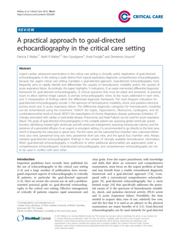
Principles of Echocardiographic Image Acquisition and Doppler Analysis11Chapter 1Principles of EchocardiographicImage Acquisition and DopplerAnalysisULTRASOUND WAVESDOPPLER ECHOCARDIOGRAPHYDoppler Velocity DataDoppler EquationSpectral AnalysisContinuous-Wave Doppler UltrasoundPulsed Doppler UltrasoundDoppler Velocity Instrument ControlsDoppler Velocity Data ArtifactsColor Doppler Flow ImagingPrinciplesColor Doppler Instrument ControlsColor Doppler Imaging ArtifactsTissue DopplerULTRASOUND TISSUE onTRANSDUCERSPiezoelectric CrystalTypes of TransducersBeam Shape and FocusingResolutionULTRASOUND IMAGING MODALITIESBIOEFFECTS AND SAFETYM-ModeTwo-Dimensional EchocardiographyImage ProductionInstrument SettingsImaging ArtifactsThree-Dimensional EchocardiographyEchocardiographic Imaging Measurementsn understanding of the basic principles ofultrasound imaging and Doppler echocardiography is essential both during data acquisitionand for correct interpretation of the ultrasoundinformation. Although, at times, current instrumentsprovide instantaneous images so clear and detailedthat it seems as if we can “see” the heart and bloodflow directly, in actuality we always are looking atimages and flow data generated by complex analysesof ultrasound waves reflected and backscattered fromthe patient’s body. Knowledge of the strengths, andmore importantly the limitations, of this technique iscritical for correct clinical diagnosis and patientmanagement. On the one hand, echocardiographycan be used for decision making with a high degreeof accuracy in a variety of clinical settings. On theother hand, if an ultrasound artifact is mistaken foran anatomic abnormality, a patient could undergoother needless, expensive, and potentially risky diagnostic tests or therapeutic interventions.In this chapter, a brief (and necessarily simplified)overview of the basic principles of cardiac ultrasoundA BioeffectsSafetyTHE ECHO EXAMSUGGESTED READINGimaging and flow analysis is presented. The reader isreferred to the Suggested Reading at the end of thechapter for more information on these subjects. Becausethe details of image processing, artifact formation, andDoppler physics become more meaningful with experience, some readers may choose to return to this chapterafter reading other sections of this book and afterparticipating in some echocardiographic examinations.ULTRASOUND WAVESSound waves are mechanical vibrations that inducealternate refraction and compression of any physicalmedium through which they pass (Fig. 1.1). Likeother waves, sound waves are described in terms of(Table 1.1): Frequency: cycles per second, or hertz (Hz)Velocity of propagationWavelength: millimeters (mm)Amplitude: decibels (dB)1
2 Chapter 1Principles of Echocardiographic Image Acquisition and Doppler AnalysisFrequency (f) is the number of ultrasound waves ina 1-second interval. The units of measurement arehertz, abbreviated Hz, which simply means cyclesper second. A frequency of 1000 cycles/s is 1 kilohertz(kHz), and 1 million cycles/s is 1 megahertz (MHz).Humans can hear sound waves with frequenciesbetween 20 Hz and 20 kHz; frequencies higher thanthis range are termed ultrasound. Diagnostic medicalultrasound typically uses transducers with a frequencybetween 1 and 20 MHz.The speed that a sound wave moves through thebody, called the velocity of propagation (c), is differentECHO MATH: WavelengthWavelength (λ) is the distance from peak to peak ofan ultrasound wave. Wavelength can be calculatedby dividing the frequency (f in Hz) by the propagationvelocity (c in m/s):λ c fPropagation velocity (m/s)(Eq. 1.1)Because the propagation velocity in the heart isconstant at 1540 m/s, the wavelength for anytransducer frequency can be calculated (Fig. 1.2) as:Amplitude (dB)Wavelengthλfor each type of tissue. For example, the velocity ofpropagation in bone is much faster (about 3000 m/s)than in lung tissue (about 700 m/s). However, thevelocity of propagation in soft tissues, includingmyocardium, valves, blood vessels, and blood, is relatively uniform, averaging about 1540 m/s.λ (mm) [1540 m s f (Hz )] 1000 mm morλ (mm) 1. 54 fFor example, the wavelength emitted by a 5-MHztransducer can be calculated as:λ 1540 m s 5, 000, 000 cycle s 0. 000308m 0. 308 mm1scycles/s HzFig. 1.1 Schematic diagram of an ultrasound wave.TABLE 1.1Ultrasound WavesDefinitionExamplesClinical ImplicationsFrequency (f)The number of cycles persecond in an ultrasoundwavef cycles/s HzTransducer frequencies aremeasured in MHz(1,000,000 cycles/s).Doppler signal frequencies aremeasured in kHz (1000cycles/s).Different transducer frequenciesare used for specific clinicalapplications because thetransmitted frequency affectsultrasound tissue penetration,image resolution, and theDoppler signal.Velocity ofpropagation (c)The speed that ultrasoundtravels through tissueThe average velocity ofultrasound in soft tissue is 1540 m/s.The velocity of propagation issimilar in different softtissues (e.g., blood,myocardium, liver, fat) but ismuch lower in lung and muchhigher in bone.Wavelength (λ)The distance betweenultrasound waves:λ c/f 1.54 / f (MHz)Wavelength is shorter with ahigher-frequency transducerand longer with a lowerfrequency transducer.Image resolution is greatest( 1 mm) with a shorterwavelength (higherfrequency).Depth of tissue penetration isgreatest with a longerwavelength (lowerfrequency).Amplitude (dB)Height of the ultrasoundwave or “loudness”measured in decibels(dB)A log scale is used for dB.On the dB scale, 80 dBrepresents a 10,000-fold and40 dB indicates a 100-foldincrease in amplitude.A very wide range of amplitudescan be displayed using agray-scale display for bothimaging and spectral Doppler.
Principles of Echocardiographic Image Acquisition and Doppler AnalysisWavelength is important in diagnostic applicationsfor at least two reasons: Decibels are logarithmic units based on a ratio ofthe measured amplitude (A2) to a reference amplitude(A1) such that:dB 20 log ( A2 A1 )20 log (1000 ) 20 3 60 dBa ratio of 100 to 1 is20 log (100 ) 20 2 40 dBand a ratio of 2 to 1 is20 log (2) 20 0. 3 6 dB(Eq. 1.2)A simple rule to remember is that a 6-dB changerepresents a doubling or halving of the signal amplitude or that a 40-dB change represents a 100 timesdifference in amplitude (Fig. 1.3).This relationship shows that if ultrasound power isdoubled, intensity is quadruped. Instead of using directmeasures of pressure energy, ultrasound amplitude isdescribed relative to a reference value using the decibelscale. Decibels (dB) are familiar to all of us as thestandard description of the loudness of a sound.300Wavelength (mm)0.5Wavelength (resolution)Penetration20.621.010Penetration (cm).2.3(Eq. 1.3)Thus a ratio of 1000 to 1 isThus there is an obvious trade-off between imageresolution (shorter wavelength or higher frequencypreferable) and depth penetration (longer wavelengthor lower frequency preferable).The acoustic pressure, or amplitude, of an ultrasound wave indicates the energy of the ultrasoundsignal. Power is the amount of energy per unit time.Intensity (I) is the amount of power per unit area:.44Chapter 1ECHO MATH: DecibelsImage resolution is no greater than 1 to 2wavelengths (typically about 1 mm).The depth of penetration of the ultrasoundwave into the body is directly related to wavelength; shorter wavelengths penetrate a shorterdistance than longer wavelengths.Intensity ( I ) Power 2 Fig. 1.2 Transducer frequency versuswavelength and penetration of the ultrasound signal in soft tissue. Wavelength hasbeen plotted inversely to show that resolution increases with increasing transducerfrequency while penetration decreases. Thespecific wavelengths for transducer frequencies of 1, 2.5, 3.5, 5, and 7.5 MHz are shown.51.5000 1 2.5 3.557.5101520Transducer frequency (MHz)Fig. 1.3 Graph of the decibel scale. The logarithmicrelationship between the decibel scale (horizontalaxis) and the amplitude ratio (vertical axis) is seen.A doubling or halving of the amplitude ratio corresponds to a 6-dB change, and a 100-fold differencein amplitude corresponds to a 20-dB change.100,000Amplitude ratio10,00010001001021006204060Decibels801003
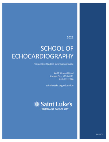
4Chapter 1 Principles of Echocardiographic Image Acquisition and Doppler AnalysisIf acoustic intensity is used instead of amplitude,the constant 10 replaces 20 in the equation so thata 3-dB change represents doubling, and a 20-dBchange indicates a 100-fold difference in amplitude.Both these decibel scales are used to refer to transmitted or received ultrasound waves or to describeattenuation effects. The advantages of the decibelscale are that a very large range can be compressedinto a smaller number of values and that low-amplitude(weak) signals can be displayed alongside very highamplitude (strong) signals. In an echocardiographicimage, amplitudes typically range from 1 to 120 dB.The decibel scale is the standard format both forechocardiographic image display and for the Dopplerspectral display, although other amplitude scales aresometimes available.ULTRASOUND TISSUE INTERACTIONAcoustic impedance (Z) depends on tissue density(ρ) and on the propagation velocity in that tissue (c):Z ρcAlthough the velocity of propagation differs amongtissues, tissue density is the primary determinant ofacoustic impedance for diagnostic ultrasound. Lungtissue has a very low density compared with bone,which has a very high density. Soft tissues, such asblood and myocardium, have much smaller differencesin tissue density and acoustic impedance. Acousticimpedance determines the transmission of ultrasoundwaves through a tissue; differences in acoustic impedanceresult in reflection of ultrasound waves at tissueboundaries.The interaction of ultrasound waves with the organsand tissues of the body can be described in terms of(Fig. 1.4):Propagation of ultrasound waves in the body to generate ultrasound images and Doppler data depends ona tissue property called acoustic impedance (Table 1.2).TABLE 1.2(Eq. 1.4) d Tissue InteractionDefinitionExamplesClinical ImplicationsAcousticimpedance (Z)A characteristic of eachtissue defined bytissue density (ρ) andpropagation of velocity(c) as:Z ρ cLung has a low density andslow propagation velocity,whereas bone has a highdensity and fastpropagation velocity.Soft tissues have smallerdifferences in tissuedensity and acousticimpedance.Ultrasound is reflected fromboundaries betweentissues with differences inacoustic impedance (e.g.,blood vs. myocardium).ReflectionReturn of ultrasoundsignal to the transducerfrom a smooth tissueboundaryReflection is used to generate2D cardiac images.Reflection is greatest withthe ultrasound beam inperpendicular to the tissueinterface.ScatteringRadiation of ultrasound inmultiple directionsfrom a small structure(e.g., blood cells)The change in frequency ofsignals scattered frommoving blood cells is thebasis of Doppler ultrasound.The amplitude of scatteredsignals is 100 to 1000times less than reflectedsignals.RefractionDeflection of ultrasoundwaves from a straightpath due to differencesin acoustic impedanceRefraction is used intransducer design to focusthe ultrasound beam.Refraction in tissues resultsin double image artifacts.AttenuationLoss in signal strengthdue to absorption ofultrasound energy bytissuesAttenuation is frequencydependent with greaterattenuation (lesspenetration) at higherfrequencies.A lower-frequency transduceris needed for apical viewsor in larger patients ontransthoracic imaging.ResolutionThe smallest resolvabledistance between twospecular reflectors onan ultrasound imageResolution has threedimensions: along thelength of the beam (axial),lateral across the image(azimuthal), and in theelevational plane.Axial resolution is mostprecise (as small as 1 mm),so imaging measurementsare best made along thelength of the ultrasoundbeam.
Principles of Echocardiographic Image Acquisition and Doppler AnalysisScattering frommoving blood cellsRefractionSpecularreflectorAttenuationFig. 1.4 Diagram of the interaction between ultrasound and body tissues.Doppler analysis is based on the scattering of ultrasound in all directionsfrom moving blood cells with a resulting change in frequency of theultrasound received at the transducer. 2D imaging is based on reflectionof ultrasound from tissue interfaces (specular reflectors). Attenuationlimits the depth of ultrasound penetration. Refraction, a change in directionof the ultrasound wave, results in imaging artifacts.ReflectionThe basis of ultrasound imaging is reflection of thetransmitted ultrasound signal from internal structures.Ultrasound is reflected at tissue boundaries andinterfaces, with the amount of ultrasound reflecteddependent on the: Chapter 1ultrasound energy radiates in all directions. Only asmall amount of the scattered signal reaches thereceiving transducer, and the amplitude of a scatteredsignal is 100 to 1000 times (40–60 dB) less than theamplitude of the returned signal from a specularreflector. Scattering of ultrasound from moving bloodcells is the basis of Doppler echocardiography.The extent of scattering depends on:TransducersReflection Difference in acoustic impedance between thetwo tissuesAngle of reflectionSmooth tissue boundaries with a lateral dimensiongreater than the wavelength of the ultrasound beamact as specular, or “mirror-like,” reflectors. The amountof ultrasound reflected is constant for a given interface,although the amount received back at the transducervaries with angle because (like light reflected from amirror) the angle of incidence and reflection is equal.Thus optimal return of reflected ultrasound occursat a perpendicular angle (90 ). Remembering thisfact is crucial for obtaining diagnostic ultrasoundimages. It also accounts for ultrasound “dropout” ina two-dimensional (2D) or three-dimensional (3D)image when too little or no reflected ultrasound reachesthe transducer resulting from a parallel alignmentbetween the ultrasound beam and tissue interface.ScatteringScattering of the ultrasound signal, instead of reflection,occurs with small structures, such as red blood cellssuspended in fluid, because the radius of the cell(about 4 µm) is smaller than the wavelength of theultrasound signal. Unlike a reflected beam, scattered Particle size (red blood cells)Number of particles (hematocrit)Ultrasound transducer frequencyCompressibility of blood cells and plasmaAlthough experimental studies show differences inbackscattering with changes in hematocrit, variationover the clinical range has little effect on the Dopplersignal. Similarly, the size of red blood cells and thecompressibility of blood cells and plasma do notchange significantly. Thus the primary determinantof scattering is transducer frequency.Scattering also occurs within tissues, such as themyocardium, from interference of backscattered signalsfrom tissue interfaces smaller than the ultrasoundwavelength. Tissue scattering results in a pattern ofspeckles; tissue motion can be measured by trackingthese speckles from frame to frame, as discussed inChapter 4.RefractionUltrasound waves can be refracted—deflected from astraight path—as they pass through a medium witha different acoustic impedance. Refraction of anultrasound beam is analogous to refraction of lightwaves as they pass through a curved glass lens (e.g.,prescription eyeglasses). Refraction allows enhancedimage quality by using acoustic “lenses” to focus theultrasound beam. However, refraction also occurs inunplanned ways during image formation, with resultingultrasound artifacts, most notably the “double-image”artifact.AttenuationAttenuation is the loss of signal strength as ultrasoundinteracts with tissue. As ultrasound penetrates intothe body, signal strength is progressively attenuatedbecause of absorption of the ultrasound energy byconversion to heat, as well as by reflection and scattering. The degree of attenuation is related to severalfactors, including the: Attenuation coefficient of the tissueTransducer frequencyDistance from the transducerUltrasound intensity (or power)The attenuation coefficient (α) for each tissue isrelated the decrease in ultrasound intensity (measured5
6Chapter 1 Principles of Echocardiographic Image Acquisition and Doppler Analysisin dB) from one point (I1) to a second point (I2)separated by a distance (l) as described by theequation:I2 I1e 2αlTransducerDampingmaterial(Eq. 1.5)The attenuation coefficient for air is very high(about 1000 ) compared with soft tissue so that anyair between the transducer and heart results insubstantial signal attenuation. This is avoided ontransthoracic examination
This textbook on general clinical echocardiography is intended to be read by individuals new to echocardiography and by those interested in updating their knowledge in this area. Thus, this book is aimed primarily at cardiology fellows on their basic echocardiography rotation but