Transcription
U.S. Department of Housing and UrbanDevelopmentOffice of Community Planning and DevelopmentNoise NotebookChapter 4SupplementSoundTransmissionClass Guidance
Table of ContentsTitlePageIntroductionWhat is SoundSound Reduction in StructuresEliminationAbsorptionSound BarriersDesignWeather and SoundSTC Ratings for Wall, Floor and Window Materials and AssembliesAppendix A STC RatingsWallsExteriorInteriorWooden StudsMetal rAppendix B A-24A-27A-27A-29B-1
Sound Transmission Class Guidancebarely audible to person with normal unimpairedhearing.IntroductionThe Noise Guidebook, pages 33-37, provides anelementary discussion of STC, provides some STCratings for common building materials and limitedexterior and interior wall construction configurations,and describes a method to determine composite STCvalue of a wall containing a window or door. Thisupdate provides for an understanding of STC andprovides an expanded material and constructionclassification for both internal and external buildingmaterials and typical construction patterns.The intent of this chapter is not to endorse anyonebuilding manufacturer or product over another but tokeep HUD Environmental staff and other interestedpersons advised on the STC values of current buildingmaterials and practices which can be applied to HUDsupported housing activities. Additional subsections onspecific types of building materials, constructiontechniques and STC values will be periodically added.As stated in the Noise Guidebook, “STC is used as ameasure of a material's ability to reduce sound,” andeffectively mitigate any adverse noise levels thatcould impede a person's use of a residential orcommercial structure. The higher the STC value, thegreater the sound attenuation and presumably thequieter the structure's interior. In addition to STC,another interior building measuring technique toevaluate sound impact or absorption between floors isthe Impact Isolation Class (IIC). Both techniques willbe fully discussed after a brief explanation of thefollowing basic principals related to sound.What Is SoundSound is indicated in two ways: frequency andintensity. Frequency, the high or low pitch of sound, isexpressed as the number of vibrations or cycles persecond. One vibration or cycle per second is a hertz(Hz). For example on a piano the middle C note has afrequency of 262 Hz and the total range of a piano hasa frequency of 27 Hz to 4186 Hz, well within the 16 to20,000 Hz range of the human ear. The sound createdby the piano is heard by the human ear by airpressure created by vibration. The greater thepressure, the greater the loudness or intensity of thesound heard by the human ear. Loudness is expressedin decibels (dB). The decibel is one-tenth of a “Bel,” aunit named for Alexander Graham Bell. Since the earis more sensitive to sound in the middle range offrequencies, loudness (intensity) is determined at afrequency of 1,000 Hz. On the decibel scale, 0 dBindicates a level of sound at 1,000 Hz, a sound just1The A-weighted scale of a sound meter is designed toadjust the sensitivity of a sound meter to sounds ofdifferent frequencies that closely approximate how thehuman ear might respond to moderate sound levels inthe 1,000 to 4,000 Hz range. The A-weighted soundlevel is used extensively for measuring communityand transportation noises.The Sound Transmission Class (STC), measured indecibels, is used to measure building material's abilityto absorb sound. The STC can be used to measuresound absorption for both external building walls andinternal walls in single and multifamily structures. TheSTC is measured by positioning a representativesample of the building material midway in anacoustical chamber, dividing the chamber in half orinto two rooms. One section of the chamber containsthe sound source and the other section the soundreceiving equipment. The test procedure calls for asteady sound in the source room and measuring thesound level in both the source and receiving rooms.Differences in sound levels in the rooms determinesthe transmission loss characteristics of the materialtested. For example, if a generated sound level of 80dB is measured in the source room and 30 dB ismeasured in the adjacent receiving room, the testedmaterial has a sound reduction intensity (STC) of5OdB.The Impact Isolation Class (IIC), measured indecibels, is the classification system used todetermine sound impact from floor to ceiling in astructure. The IIC is not to be used to measureairborne sound penetration or absorption in walls. TheIIC numerical rating efficiency increases withimproved impact isolation performance of the floorand its component sub flooring and materials. Therating scale values are generally equivalent to theairborne sound transmission loss. The impact of stepsor vibrations on a floor and the reverberation of thatnoise in the room below is dependent upon the type,density and thickness of the floor and ceiling material,its absorption material, and quality of construction. Aseparate section on common floor materials andconstruction patterns to illustrate both the STC andIIC ratings is included.Sound Reduction In StructuresFour general techniques for controlling noise in singlefamily and multifamily structures are:1. Elimination of the cause or source of the noise,2. Employ materials which absorb sound rather thanreflect noise,
3. Use sound barriers in building layout to preventsound from being transmitted from one adjoiningarea into another, and4. Use design considerations to mask or absorb thenoise.leakage will occur through any opening in a wall. Animproperly fitted door or window is a prime source ofsound leakage, as well as openings around ducts,pipes and electrical outlets which are improperly fittedor sealed.A description of each technique and its applicabilityfollows.3. SOUND BARRIERS:Prudent building layout can be effective in controllingnoise in single-family and multifamily housing. Soundwaves can be prevented from being transmitted fromone adjoining area to another. Closets, stairways andcorridors can be used as buffers against airbornesound transmission between apartments or bedrooms.Concrete blocks or solid partitions can be employed toseparate boiler rooms, air conditioning units, workareas or noisy public areas such as stairwells,corridors or lobbies from adjacent living areas.Partitions designed to absorb sound on one side andto retain sound absorption on the other can effectivelyblock or reduce sound transmission into living areasintended for quiet use. The barrier should have a highsound absorption coefficient on one side and anequally high sound retention coefficient on the reverseside to effective. For example, unpainted porousconcrete block would have a high sound absorptioncoefficient and a high noise retention coefficient onthe reverse side if the porous surface in the living unitwas effectively sealed by plaster or paint. Similarly,noise originators such as cloths washing machines,central heaters, and other noisy major appliances canbe placed in a basement or utility rooms that arephysically isolated from other living areas by walls orfloors to absorb or block the emitted sounds.1. ELIMINATION:The elimination of a noise source may be impracticalor impossible to achieve, whether emanating fromwithin or outside the structure. Examples include theoperation of mechanical equipment within the dwellingunit, excessive corridor noise, air conditioning/heatingsystem, elevators, exhaust fans, and outdoortransportation sounds such as automotive traffic,aircraft overflights, and commercial or industrialactivities. Some noise reduction could be achievedthrough sound reduction or absorption techniques, buttotal elimination of these sounds may be impossible.2. ABSORPTION:Sound absorption control is the reduction of soundemanating from a source within a room. The extent ofcontrol depends upon the efficiency of the room'ssurfaces in absorbing rather than reflecting soundwaves. A surface, which could theoretically absorb100% of the sound would have a sound absorptioncoefficient of 1.0. A surface absorbing 35% of thesound would have a coefficient of 0.35. Theeffectiveness of wall construction as a means of soundabsorption is tested in a similar manner as that ofSTC. If a generated sound level of 80 dB is observedin one room and 30 dB is measured in an adjacentroom, the reduction in sound absorption for theintervening wall is 50 dB. In choosing the type ofconstruction material for interior walls to absorbsound transmission, porosity and density of thematerial should be considered. Resistance to soundtransmission increases with unit weight and decreaseswith porosity. For example, unpainted, open texturedconcrete block exhibits improved resistance to soundpassage after sealing the surface with plaster or paint.The sealing of the pores result in a reduction in thesound absorption of the block. In multifamilystructures using concrete block partitions to separatepublic areas such as stairwells and corridors fromadjacent living areas, sound transmission reduction isachieved through plastering or painting the surface ofthe residential unit or living area on the opposite sideof the partition. The sound is absorbed by theconcrete masonry's unpainted side and itstransmission is prevented into the residential unit orliving area by the plaster or paint on the other side.However, all of the design elements that areemployed to control sound can be nullified throughpoor or improper construction practices. Sound24. DESIGN:Design factors is the last major element to consider incontrolling noise in single-family and multifamilystructures. Design considerations offer the mostinfinite prospects for controlling noise due to thenumerous types of building designs. For example,adjacent apartments can be arranged to have quietareas (bedrooms or living rooms) abut and have noisyareas (kitchens and bathrooms) next to similar noisyareas. Apartment door openings into the samehallway can be staggered to reduce sound penetrationinto the unit directly across the hall. Since soundtravels in a straight line, some of the sound from onedoorway would be absorbed or diffused into the wallbuilding material of the unit directly across the hall.Windows should be placed as far away as possiblefrom common walls. The closer the windows are toeach other, the more sound will pass from oneapartment to another. Medicine cabinets in oppositebathroom partitions should be offset. Cabinets placedback-to-back will transmit almost as much noise as anopening. Heating/cooling ducts are like speakingtubes, carrying noise from one room to another.Techniques should be employed to trap or splinter
sound or have turns in the ducts to reduce noisetransference.impact of rain on lightweight roofing, gutters orskylights can produce high internal noise levels.Noise producing equipment should be kept as far aspossible from living areas and especially thebedrooms. Flexible connectors should be used tocouple mechanical equipment to pipes and ducts.Pipes and ducts should not be firmly connected toparts of a building that could serve as soundingboards but be supported by resilient connections tosolid supports. Where pipes and ducts pass throughwalls and floors, they should be isolated by gaskets.The acoustical integrity of a building or a buildingsection with an otherwise adequate STC rating can besignificantly reduced by a small hole or crack in theexterior wall or any other path that allows sound tobypass the exterior or interior walls and flow intoother areas of the structure.STC Ratings for Wall, Floor and WindowMaterials and AssembliesWeather and SoundAir will attenuate noise at high frequencies usuallyfrom 1,000 Hz upwards. Sound absorption by airchanges with wind speed, temperature and humidity.For example, wind blowing at slower speeds near theground surface than at higher elevations will producea bending of the sound upwards, resulting in lessnoise at ground level. Temperature gradients have asimilar effect because the velocity of sound increaseswith the higher temperatures. If the temperature ishigher near the ground than in the upper layers(usually the case during the day), the sound waveshigher above the ground will travel slower and thesound will be bent upwards resulting in quieterconditions at ground level. The reverse is true atnight, the temperature is lower near the ground,sound will bend towards the ground, increasing noiseat the ground level. Wind and temperature- gradienteffects can also account for the occasional freakreception of sounds over long distances, especiallytrain whistles. The sound has been bent upwards by atemperature or wind gradient and after traveling someway at high level is bent down again by a reversegradient.Weather conditions can produce substantial variationsof as much as - 10 dB. For example, fog causes anincrease in the absorption in the air. A moderatelydense fog, visibility 150 feet, gives extra attenuationof 1 to 3 dB per 300 feet, depending on frequency.Similarly, snow forms an absorbent layer on theground, which affects ground reflection, therebyreducing the sound level.Weather can also be a significant source of noise in astructure. Common irritants are wind and rain. Windwhistling around a building, into ventilation grilles,screens or past other external architectural or artisticfeatures can result in disturbing noise. Similarly, the3Appendix A illustrates sound transmission class ratingsfor wall, floor, window and door assemblies. The dataused in this section is compiled from laboratoryreports and various technical and trade literaturepublications received by this Office. Each item has anassigned STC rating, an accompanying sketch and abrief description of its composition or assembly. Inaddition, where possible, an Impact Isolation Class(IIC) rating has been assigned to floors to determinesound impact from floor to ceiling. Appendix A is aguide designed to aid HUD Housing and Environmentalpersonal in determining STC values for most commonhousing construction practices and materials used inresidential construction. The STC information can beused to supplement acoustical measurements byproviding approximate interior noise levels for existingor proposed dwellings located in high noise areas bydeducting the STC value from the exterior noise level.The data could also be used to advise HUD clients indetermining and achieving compliance with the noisecriteria stated in 24 CFR Part 51 B through the use ofcommon construction materials and techniques toachieve noise attenuation for new construction andrehabilitation.The appendix is divided into the following subsections:1. WALLSExteriorInterior2. FLOORSWoodConcrete3. WINDOWS4. DOORSExteriorInteriorA bibliography of the reports, manufacturer's catalogs,technical papers, testing laboratories and otherpublications used in compiling this data is listed in theAppendix B.
Appendix A STC Ratings
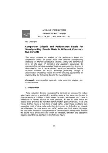
Appendix AWalls: ExteriorSTC RatingsSketchBrief Description1. 4” face brick, mortared together.STC451. Hollow core brick, mortared together.511. Common brick, mortared together.2. ½” gypsum/sand plaster.501. Hollow core brick, mortared together.2. ½” gypsum/sand plaster.531. Face brick, mortared together.2. 2” air space.3. Metal ties.501. Brick, mortared together.2. 2 ¼” cavity filled with concrete grout and #6 barsvertically 48”o.c. and #5 bars horizontally 30”o.c.59A-1
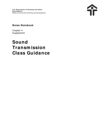
SketchBrief Description1. Common brick, mortared together.2. Face brick, mortared together.STC591. Common brick, mortared together.2. ¾” mortar-filled cavity with metal Z ties 24”o.c. inboth directions.3. 1x3” furring strips 16”o.c. and nailed vertically intomortar joints 12”o.c.4. ½” gypsum board nailed 8”o.c. along edges and12”o.c. in field.1. 4x8x16” 3-cell lightweight concrete masonry units(17 lbs./block).531. 4x8x18” 3-cell lightweight concrete masonry units(19 lbs./block).2. 2” air cavity.3. Common brick, mortared together.541. 4x8x18” 3-cell lightweight concrete masonry units(19 lbs./block).2. Common brick, mortared together. (brick headersafter every second course of block to tie the withestogether).511. 4x8x18” 3-cell lightweight concrete masonry units(19 lbs./block).2. Common brick, mortared together.3. Resilient channels.4. ½” gypsum board screwed to channels.56A-240
SketchBrief Description1. 6x8x16” 3-cell lightweight concrete masonry units(21 lbs./block).STC441. 6x8x16” 3-cell lightweight concrete masonry units(21 lbs./block).2. Paint both sides with primer-sealer coat and finishcoat of latex.461. 6x8x18” 3-cell dense concrete masonry units (36lbs./block).2. Paint both sides with primer-sealer coat and finishcoat of latex.481. 6x8x16” 3-cell lightweight concrete masonry units(21 lbs./block).2. Paint, primer-sealer coat and finish coat of latex.3. Resilient channels, 24”o.c.4. ½” gypsum board screwed to channels.531. 8x8x16” 3-cell lightweight concrete masonry units(28 lbs./block).451. 8x8x18” 3-cell lightweight concrete masonry units(34 lbs./block).49A-3
SketchBrief Description1. 8x8x18” 3-cell lightweight concrete masonry units(38 lbs./block).STC491. 8x8x18” 3-cell lightweight concrete masonry units(34 lbs./block).2. Expanded mineral loose-fill insulation.511. 8x8x18” 3-cell lightweight concrete masonry units(38 lbs./block).2. Expanded mineral loose-fill insulation.511. 8x8x18” 3-cell lightweight concrete masonry units(33 lbs./block).2. Grout in cells.3. #5 bar in each cell.481. 8x8x18” 3-cell lightweight concrete masonry units(33 lbs./block).2. Grout in cells.3. #5 bar each cell.4. Paint two coats flat latex each side.551. 12x8x16” 3-cell lightweight concrete masonry units(43 lbs./block).39A-4
SketchBrief Description1. 12x8x16. 3-cell lightweight concrete masonry units(43 lbs./block).2. Paint both sides with 3 coats of latex block filler.STC501. 12x8x16” 3-cell lightweight concrete masonry units(43 lbs./block).2. Paint one side only with 3 coats latex block filler.511. 6” cast concrete wall (71 psf).571. 6” cast concrete wall.2. “Z” furring channels.3. ½” gypsum board.591.2.3.4.6” cast concrete wall.“Z” furring channels.1”, 8-pcf rockwool.½” gypsum board.621.2.3.4.6” cast concrete wall.2x2” wood furring.1 ½” 4-pcf rockwool.½” gypsum board.63A-5
SketchBrief Description1. 8” cast concrete wall (96.6 psf).STC581. 8” cast concrete wall.2. 2x2” wood furring.3. ½” gypsum board.591.2.3.4.8” cast concrete wall.2x2” wood furring.1 ½”, 4 psf rockwall.½” gypsum board.631.2.3.4.5.6.Face brick.½” air space, with metal ties.¾” insulation board sheathing.2x4” studs 16”o.c.Resilient channel.½” gypsum board.541.2.3.4.5.6.7.Face brick.½” air space, with metal ties.¾” insulation board sheathing.2x4” studs 16”o.c.Fiberglas building insulation (3 ½”).Resilient channel.½” gypsum board.56A-6
SketchBrief Description1. Face brick (9x14’ wall).2. ½” air space, with metal ties.3. ¾” insulation board sheathing.4. 2x4” studs 16”o.c.5. Fiberglas building insulation (3 ½”).6. Resilient channel.7. ½” gypsum board.8. Wall penetrated by 6x5' picture window 1” glazedinsulating glass.STC391.2.3.4.5.7/8” stucco.No.15 felt building paper and 1” wire mesh.2x4” studs 16”o.c.Resilient channel.½” gypsum board screwed to channel.491.2.3.4.5.6.7/8” stucco.No.15 felt building paper and 1” wire mesh.2x4” studs 16”o.c.Fiberglas building insulation (3 ½”).Resilient channel.½” gypsum board screwed to channel.571.2.3.4.5.5/8 x 10” redwood siding.½” insulation board sheathing.2x4” wood studs 16”o.c.Resilient channel.½” gypsum board screwed to channel.43A-7
SketchBrief Description1. 5/8x10” redwood siding.2. ½” insulation board sheathing.3. 2x4” wood studs 16”o.c.4. Fiberglas building insulation (3 ½”).5. Resilient channel.6. ½” gypsum board screwed to channel.STC471.2.3.4.5.6.7.(a.38)(b.35)5/8x10” redwood siding (9x14' wall).½” insulation board sheathing.2x4” wood studs 16.o.c.Fiberglas building insulation (3 ½”).Resilient channel.½” gypsum board screwed to channel.a.Wall penetrated by a 6x5' picture window, 1”glazed insulating glass.Wall penetrated by a 6x5' 16 panel window,glazed single strength.b.A-8
SketchWALLS: Interior: Wooden StudsBrief Description1. ½” gypsum board.2. 3/16” plywood laminated with contact cement.STC281. ½” gypsum board.2. ½” wood-fiber board laminated with gypsum jointcompound.301. 2x4” studs, 16”o.c.2. 5/8” gypsum board screwed to studs.281. ½” gypsum board, no studs.2. 2 ½” air space.301. ½” gypsum board, no studs.2. 2 ½” air space.3. 2” thick sound attenuation blanket.441. ½” gypsum board, no studs.2. 3 5/8” air space.3. 2” thick sound attenuation blanket.451. 1 3/8” thick wood-fiber board nailed to 2x4” platestop and bottom and painted both sides.2. 3 ½” air cavity.44A-9
SketchBrief Description1. ½” gypsum board, no studs.2. ½” gypsum board laminated to base layer withgypsum joint compound.3. 3 5/8” air cavity.4. 2” thick sound attenuation blanket.STC481. 2x4” studs, 16”o.c.2. 3/8” gypsum board nailed to studs.351. 2x4” studs, 16”o.c.2. 3/8” gypsum board nailed to studs.3. 3” thick sound attenuation blanket.411. 2x4” studs, 16”o.c.2. ½” gypsum board screwed to studs.341. 2x4” studs, 16”o.c.2. ½” gypsum board screwed to studs.3. 2” thick sound attenuation blanket.371. 2x4” studs, 24”o.c.2. ½” gypsum board screwed to studs.36A-10
SketchBrief Description1. 2x4”studs, 24”o.c.2. ½” gypsum board screwed to studs.3. 2” thick sound attenuation blanket.STC401. 2x4” studs spaced 16”o.c. and staggered 8”o.c. on2x6” plates.2. ½” gypsum board screwed 12”o.c.391. 2x4” studs spaced 16”o.c. and staggered 8”o.c. on2x6” plates.2. ½” gypsum board screwed 12”o.c.3. 2 ¼” thick sound attenuation blanket.481. 2x4” studs spaced 16”o.c. and staggered 8”o.c. on2x6” plates.2. ½” gypsum board screwed 12”o.c.3. 3 ½” thick sound attenuation blanket.491. 2x4” studs spaced 16”o.c. and staggered 8”o.c. on2x6” plates.2. ½” gypsum board screwed 12”o.c.3. 2 ¼” thick sound attenuation blankets in both studcavities.491. 2x4” studs spaced 16”o.c. and staggered 8”o.c. on2x6” plates.2. ½” gypsum board screwed 12”o.c.3. 3 ½” thick sound attenuation blankets in both studcavities.51A-11
SketchBrief Description1. 2x4” studs spaced 24”o.c. and staggered 12”o.c. on2x6” plates.2. ½” type X gypsum board screwed 12”o.c.STC421. 2x4” studs spaced 24”o.c. and staggered 12”o.c. on2x6” plates.2. ½” gypsum board screwed to studs.3. 2” thick sound attenuation blanket.461. 2x4” studs spaced 24”o.c. and staggered 12”o.c. on2x6” plates.2. ½” type X gypsum board screwed 12”o.c.3. 2” thick sound attenuation blankets in both studcavities.481. Double row of 2x4” studs 16”o.c. on separate platesspaced 1” apart.2. ½” type X gypsum board screwed 12”o.c.471. Double row of 2x3” studs 16”o.c. on 2x3” platesspaced 2 ½” apart.2. ½” gypsum board screwed 16”o.c.3. 2 ¼” thick sound attenuation blanket.551. Double row of 2x4” studs 16”o.c. on separate platesspaced 1” apart.2. ½” type X gypsum board screwed 12”o.c.3. 3 ½” thick sound attenuation blanket.56A-12
SketchBrief Description1. Double row of 2x4” studs 16”o.c. on separate platesspaced 1” apart.2. ½” gypsum board screwed 12”o.c.3. 2 ¼” thick sound attenuation blankets in both studcavities.STC561. Double row of 2x4” studs 16.o.c. on separate platesspaced 1” apart.2. Double row of 5/8” type X gypsum board screwed16.o.c.3. 3 ½” thick sound attenuation blankets in both studcavities.63A-13
SketchWALLS: Interior: Metal StudsBrief Description1. 1 5/8” metal studs, 24”o.c.2. 1/2. vinyl-faced gypsum board screwed to studs.STC271. 1 5/8” metal studs spaced 24”o.c. and staggered12”o.c. on 2 ½” metal tracks.2. 1/2” gypsum board screwed to studs.341. 1 5/8” metal studs, 24”o.c.2. 5/8” gypsum board screwed 12”o.c. at edges and24”o.c. in field.371. 1 5/8” metal studs spaced 24”o.c. and staggered12”o.c. on 21/2” metal channels.2. 5/8” gypsum board screwed to studs.381. 2 ½” metal studs, 24”o.c.2. 1/2” vinyl-faced gypsum board screwed to studs.271. 2 1/2” metal studs, 24”o.c.2. 5/8” gypsum board screwed to studs.37A-14
SketchBrief Description1. 2 ½” metal studs, 24”o.c.2. 5/8” gypsum board screwed 12”o.c. at edges and24”o.c. in field.3. 1 ½” thick sound attenuation blanket.STC421. 2 ½” metal studs, 24”o.c.2. ½” gypsum board screwed to studs.3. 2” thick sound attenuation blanket.441. 3 5/8” metal studs, 24”o.c.2. 1/2. gypsum board screwed to studs.271. 3 5/8” metal studs, 24”o.c.2. ½” gypsum board screwed to studs.361. 3 5/8” metal studs, 24”o.c.2. ½” gypsum board screwed to studs.3. 2” thick sound attenuation blanket.44A-15
SketchFloors: WoodBrief Description1. 2x8” wooden joists, 16”o.c.2. 7/8” tongue and groove nailed to joints.3. 3/8” gypsum nailed to joints.1.2.3.4.5.2x8” wooden joists, 16”o.c.½” plywood nailed.25/32” hardwood flooring.1/2” gypsum nailed to joists.Ceiling tire.STC(IIC)NA(32)NA(37)1. 2x8” wooden joists, 16”o.c.2. 5/8” tongue and groove plywood nailed with 8dnails 6”o.c.3. 3/8” plywood stapled 3”o.c. at edges and 6”o.c. infield.4. .075” sheet vinyl.5. Resilient channels, 24”o.c.6. 5/8” gypsum board screwed 12”o.c.7. 3” thick sound attenuation blanket.1. 2x8” wooden joists, 16”o.c.2. 5/8” plywood nailed with 8d nails.3. ½” nominal wood-fiber board glued to plywood.4. 44 oz. carpet on 50 oz. pad.5. Resilient channels, 24”o.c.6. 5/8” gypsum board screwed 12”o.c.46(44)1. 2x8” wooden joists, 16”o.c.2. 19/32” tongue and groove plywood nailed with 8dnails 6”o.c. at edges and 10”o.c. in field.3.a. 44 oz. carpet on 40 oz. hair pad.b. .075” sheet vinyl.c. 1/16” sheet vinyl.4. Resilient channels, 24”o.c.5. 5/8” gypsum board screwed 12”o.c.6. 3” thick sound attenuation blanket.48A-1648(65)(a. 69)(b. 45)(c.43)
SketchBrief Description1. 2x8” wooden joists, 16”o.c.2. 1 1/8” tongue and groove plywood nailed 6”o.c. atedges and 16”o.c. in field.3. 44 oz. wool carpet on 40 oz. hair pad.4. 2x4” ceiling joists, 16”o.c. and staggered betweenfloor joists.5. 5/8” gypsum board nailed to 2x4” joists.6. 3” thick sound attenuation blanket.1. 2x8” wooden joists, 16”o.c.2. 1/2” plywood nailed with 8d nails 6”o.c. at edgesand 16”o.c. in field.3. 25/32” wood strip flooring nailed to sub floor.4. 2x4” wooden ceiling joists, 16”o.c. and staggeredbetween floor joists.5. 5/8” gypsum board nailed to 2x4” joists.6. 3” thick sound attenuation blanket.1. 2x10” wooden joists, 16”o.c.2. 1 11/32” tongue and groove wood-fiber board.3. 44 oz. wool carpet on 40 oz. hair pad.4. Resilient channels, 24”o.c.5. 5/8” gypsum screwed 12”o.c.1. 2x10” wooden joists, 16”o.c.2. 19/32” tongue and groove plywood.3.a. Carpet and pad.b. Vinyl tile.4. Resilient channels, 24”o.c.5. 5/8” gypsum screwed 12”o.c.6. 1” thick sound attenuation blanket.A-17STC(IIC)53(80)54(45)49(68)51(a. 74)(b.51)
SketchBrief Description1.2.3.4.5.6.2x10” wooden joists, 16”o.c.1 11/32” tongue and groove wood-fiber board.40 oz. wool carpet on 80 oz. sponge rubber pad.Resilient channels, 24”o.c.1/2” gypsum board screwed 12”o.c.3” thick sound attenuation blanket.STC(IIC)50(72)1. 2x10” wooden joists, 16”o.c.2. 5/8” plywood sub floor glued to joists, nailed with8d nails 12”o.c.3. ¼” particleboard glued to plywood.4. ½” parquet wood flooring glued to particleboard.5. ½” type-X gypsum board screwed 12”o.c.6. 3” thick sound attenuation blanket.43(NA)1. 2x10” wooden joists, 16”o.c.2. 5/8” tongue and groove plywood nailed with 8dnails 6”o.c. along edges and 10”o.c. in field.3. Two layers of 5/8” gypsum board attached withscrews 12”o.c. to underside of sub floor.4.a. 44 oz. carpet on 40 oz. hair pad.b. 1/16” vinyl asbestos tile.5. Resilient channels, 24”o.c.6. 5/8” gypsum board screwed 12”o.c.7. 3 ½” thick sound attenuation blanket.1. 2x10” wooden joists, 16”o.c.2. 5/8” tongue and groove plywood nailed with 8dnails 6”o.c. along edges and 10”o.c. in field.3.a. 44 oz. carpet on 40 oz. hair pad.b. 1/16” vinyl asbestos tile.4. 5/8” gypsum board nailed 7”o.c.5. Two layers of 5/8” gypsum board suspended bywire hangers 5” long in a 2x4' heavy-duty T gridceiling system.6. 3 ½” thick sound attenuation blanket.56A-18(a. 74)(b.50)49(a. 68)(b.47)
SketchBrief Description1. 2x8” wooden joists, 16”o.c.2. 5/8” tongue and groove plywood nailed to joistswith 8d nails 6”o.c. at edges and 10”o.c. in field.3. 1 5/8” lightweight concrete over 4 mil. polyethylenefilm.4. 44 oz. carpet on 40 oz. hair pad.5. 5/8” gypsum board nailed to joists.STC(IIC)47(66)1. 2x8” wooden joists, 16”o.c.2. 5/8” tongue and groove plywood nailed to joistswith 8d nails 6”o.c. at edges and 10”o.c. in field.3. 1 5/8” thick lightweight concrete over 4 mil.polyethylene film.4.a. 44 oz. carpet on 40 oz. hair pad.b. .075” sheet vinyl.5. Resilient channels, 24”o.c.6. 5/8” gypsum board screwed 12”o.c.7. 3” thick sound attenuation blanket.1. 2x10” wooden joists. 16”o.c.2. 5/8” plywood nailed to joists.3. 3. 1 ½” thick lightweight concrete, 13 psf.4. Cushioned vinyl.5. Resilient channels, 24”o.c.6. 5/8” gypsum board screwed to channels.7. 3 ½” thick sound attenuation blanket.531. Plywood web I-beams 12” deep and 24”o.c.2. 3/4” plywood sub floor nailed with 6d nails 6”o.c. atedges and 10”o.c. in field.3. 1 ½” thick lightweight concrete, 15 psf.4. Resilient channels, 24”o.c.5. 5/8” gypsum board screwed 12”o.c.57(NA)A-19(a. 74)(b. 47)NA(51)
SketchBrief DescriptionSTC(IIC)1. Plywood web I-beams 12” deep and 24”o.c.2. 3/4” plywood sub floor nailed with 6d nails 6”o.c. atedges and 10”o.c. in field.3. 1 1/2” thick lightweight concrete, 15 psf.4.a. 44 oz. carpet on 40 oz. hair pad.b. .07” vinyl tile.5. Resilient channels, 24.o.c.6. 5/8” gypsum board screwed 12”o.c.7. 3” thick sound attenuation blanket.1. 2x10” wooden joists, 16”o.c.2. 5/8” plywood glued to joists, nailed with 8d nails12”o.c.3. ¼” particleboard glued to plywood.4. ½” fiberboard glued to particleboard.5.a. 76 oz. carpet on 50 oz. hair pad.b. 1/2” parquet wood flooring.6. Resilient channels, 24”o.c.7. ½” type-X gypsum boar
indicates a level of sound at 1,000 Hz, a sound just barely audible to person with normal unimpaired hearing. The A-weighted scale of a sound meter is designed to adjust the sensitivity of a sound meter to sounds of different frequencies that closely approximate how the human ear might respond to moderate