Transcription
Power Flame IncorporatedDirector SCS Supervisory Control SystemInstruction Manual09/09/2010 Rev. 9
Introduction :The Director SCS is designed to provide an operator interface to the Siemens LMVburner management systems. Graphic display of all important boiler process variables andcontrol parameters are combined on one display. Also available is trending of importantboiler process information as well as alarm status, history and Lead / Lag functions.2
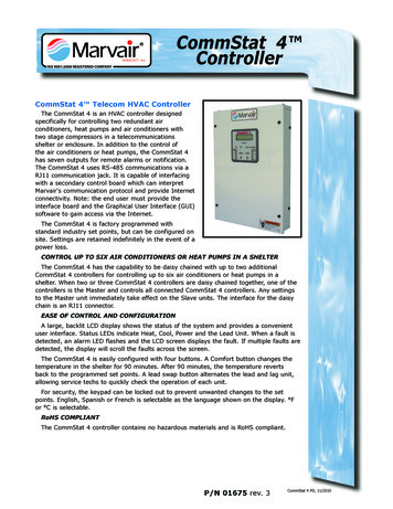
Navigating the Director SCS :Main ScreenThe setup button takes you to a setupscreen where things like the date andtime are set. Refer to page 12 for details.These buttons are used to navigate to the various screensavailable for viewing. Buttons include Boiler Status andControl, Online Trends, Historical Trends, Alarm History,and Current Alarm Status Screens.These buttons are used to navigate to the various screensavailable for viewing. Buttons include System Overview,Trends, Totalizers, Alarm History, Setup, and CurrentAlarm Status Screens.3
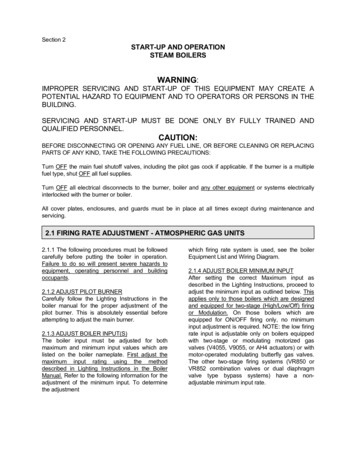
System OverviewThis is the general overview screen of the lead/lag system. A briefstatus of each boiler is displayed along with the system setpoint andthe system temperature.This displays the current header temperature as well as the desired header setpoint. The current active setpointis indicated and is displayed. The setpoint can be changed by touching the white box and entering in a newsetpoint. Night and Weekend Setback Enable/Disable status is also indicated here.150 PSI150 PSIThese timers display the time remainingbefore thesystemadvancesto thenext boiler or shuts down a lag boiler. Italso shows the time remaining for boilerwarming (if enabled). When active, theThis button opens a window where theboiler sequence can be changed and boilerscan be enable or disable in the lead lagsequence.Boiler status, setpoint, temperature, and outputare displayed for each boiler. Lead/lag information is also displayed including boiler sequence,boiler availability, and whether the boiler outputis locked or modulating. Pressing the “BoilerDetail” button opens a screen with more detailedinformation for that boilerThese buttons navigate to other screens. The “Change LeadLag Sequence” button displays the screen to change thelead/lag boiler sequence.4* Screen may vary slightly depending on configuration
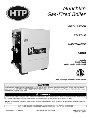
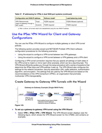
Boiler Detail*This box displays important data fromthe AZL display such as burner status,output, flame signal, etc.This is where you control the operating mode and setpoint of theburner when setpoints are set through the Director SCS. The boilersetpoint is displayed when in automatic mode and manual outputsetpoint is displayed when in manual mode. When control is releasedto the AZL, no setpoints are displayed. When the lead lag system isenabled, no setpoints are displayed.This button selects between setpoint control in the AZL or bythe Director SCS panel. Whenthe lead lag system is enabled,this button is not displayed.This box displays counter andrun-time data stored in the AZLdisplay. Pressing the reset button resets the counters to zero.This area contains graphical information of the various valves andactuators attached to the system. Items that are green indicate thatthey are “energized” while being red indicates “off”. Angular positions of actuators are displayed here as well. The backgroundcolor of the process variable display changes from black to bluewhen 5 units below the setpoint and black to red when 5 unitsabove the setpoint5These buttons navigate to other screens.* Screen may vary slightly depending on configuration
Lead Lag Setup1. Set the desired setpoint for the systemThis displays the current header pressure as well as the desired header setpoint. The current active setpointis indicated and is displayed. The setpoint can be changed by touching the white box and entering in a newsetpoint. Night and Weekend Setback Enable/Disable status is also indicated here. The outdoor reset temperature settings are accessed via the “Outdoor Reset Setup” button.2. Lead Lag Series/Unison (Parallel) SelectionSelect whether the lead/lag system operates in series or unison mode. In series mode, the system will holdthe boilers at the “Locked Boiler Output Setting” while modulating the active boiler up and down. Unisonmode modulates all active boilers up and down at the same output. This mode is also known as Parallel.3. Set the Event SettingsThe “Boiler Startup Time” setting is loaded into a timer that is triggered to countdown to zero when the systemcalls for another boiler to turn on. Until this timer reaches zero, the program pauses the checking of the boileroutput to the “SP Trigger to Shutdown the Lag Boiler” setpoint. This is to allow the boiler time to startup andmodulate before comparing it to the “SP Trigger to Shutdown the Lag Boiler” setpoint.The “SP Trigger to Start the Next Boiler” setting is the setpoint used to compare with the active modulatingboiler’s output to determine whether to start the next boiler in the lead/lag sequence. When the active modulating boiler’s output is above this setpoint, the program loads the “Next Delay” time into a countdown timer andcontinues to countdown to zero. If the active modulating boiler’s output falls below this setpoint, the counterstops and is reset back to the “Next Delay” value.When the counter reaches zero, the system locks the active boiler at the “Locked Boiler Output” setting and tellsthe next boiler to startup.Note: The SP Trigger % value should be higher than the locked boiler output value.6
Lead Lag Setup cont.3. Set the Event Settings continuedThe “SP Trigger to Shutdown the Lag Boiler” setting is the setpoint used to compare with the active modulatingboiler’s output to determine whether to shutdown the active boiler. When the active modulating boiler’s outputis below this setpoint, the program loads the “Stop Delay” time into a countdown timer and continues to countdown to zero. If the active modulating boiler’s output rises above this setpoint, the counter stops and is resetback to the “Stop Delay” value.When the counter reaches zero, the system shuts down the active boiler and releases the previous boiler in thesequence to modulate.The “Stop Delay” setting is a time value used to determine how long the active boiler’s output is below “SP Trigger to Shutdown the Lag Boiler” setting before shutting down the active boiler and releasing the previous boilerto modulate.The “Next Delay” setting is a time value used to determine how long the active boiler’s output is above “SP Trigger to Start the Next Boiler” setting before locking the active boiler and telling the next boiler in the sequence tostartup.Once the “Next Delay” timer has countdown to zero, the system locks the active boiler to the “LockedBoiler Output” setting and holds it there.Note: Set the Locked Boiler Output to an output that is the difference from low fire output of the lag boilerto the high fire output of the lead. In short, the less turndown you have on your burner the lower the LockedBoiler Output setting will need to be.7
4. Set the header setpoint PID valuesThis is the proportional control settings for the lead lag system. The system compares the difference of the system setpoint to the actual system value. Using the PID settings above, the Director SCS then calculates the setpoint for each boiler. The “Maximum Setpoint Deviation” value limits the difference in individual boiler setpoint to the system setpoint. Typical values for the Proportional Band is 5.0 to 20.0. Typical values for the Integral Band is 2.5 to 10.0. Integral Band Time is normally only used on steam systems and will usually be from1.0 to 10 seconds. On hot water systems set the Integral Band Time to 0.0. All of these settings must be tunedfor the particular system being controlled . Be careful not to set the “Maximum Setpoint Deviation” value toohigh as large swings in pressure to temperature will result. To tune the system; set the “Maximum Setpoint Deviation” to zero and tune the LMV’s for correct response to the loads. After the individual LMV’s are tuned andthe system is lined out. Put in a Maximum Setpoint Deviation that is just a little more than the offset from theheader Setpoint and the actual header pressure while running. 2 to 5 PSI on steam systems and 5 to 10 degreeson hot water systems. Then tune the Lead/Lag PI or PID setting to get the overall system response you want.Remember that you must fully tune the PID loops of the LMV’s before attempting to tune the overall system.8
Lead Lag Setup cont.5. Enable Boilers and Set sequenceFirst enable the boilers desired in the sequence.(hint– press the enable button for each boiler inthe desired sequence). The current sequence isshown in grey boxes. If a boiler is offline orlocked out in alarm, “Unavailable” will appearin the grey box for that boiler.If a different sequence is desired,press the white box above each boilernumber and enter the new number.Press “Save Sequence” to apply thenew boiler sequence.6. Auto RotationSet the number of hours between boiler rotations. This feature can be disabled or enabled.7. Boiler WarmingSet the water temperature that you want the burner to come on at and the temperature that you want theburner to go off at. When the temperature of the water in the boiler drops to the set temperature the lagboilers will start up and run at the specified output until the water temperature setpoint is reached. Thisfunction can be Enabled or Disabled by touching the Enable/Disable button.9
Lead Lag Setup cont.7. Night and Weekend SetbackEnter setpoint to use during the nightand weekend setback periods.Enter start and end times for the nightand weekend setback period.Countdown timer indicated how muchtime is left until the setpoint shifts backto the daytime setpoint.Indicates whether the night and/or theweekend setback is enabled or disabled.These buttons activate/de-activate the night and weekend setback feature. Note: Both featurescan be enabled or disabled independently.10
Lead Lag Setup cont.8. Outdoor ResetEnter the outdoor temperaturewhere the steam header setpointwill be at its maximum setting.Enter the header pressuresetpoint for the low outdoortemperature setting.Enter the outdoor temperaturewhere the steam header setpointwill be at its minimum setting.Enter the header pressuresetpoint for the high outdoortemperature setting.Enable or disable the outdoor reset function.11
Example of Series Lead/Lag Operation1. All boilers are off and enabled in the lead/lag system.2. The system setpoint is zero.3. Operator changes the system setpoint to 160 PSI.4. The first boiler starts up and begins to modulate.5. System load increases and the boiler output increases.6. Boiler output rises above the “SP Trigger to Start the Next Boiler” setting.7. The “Next Delay” timer begins to countdown and reaches zero.8. The second boiler is told to start up and the “Boiler Startup Time” is counted down.9. The second boiler starts up and begins to modulate before the “Boiler Startup Time” timer counts downto zero.10. The first boiler is locked at the “Locked Boiler Output” setting.11. The system load continues to increase and the second boiler’s output increases.12. The second boiler’s output rises above the “SP Trigger to Start the Next Boiler” setting.13. The “Next Delay” timer begins to countdown and reaches zero.14. The third boiler is told to start up and the “Boiler Startup Time” is counted down.15. The third boiler starts up and begins to modulate before the “Boiler Startup Time” timer counts downto zero.16. The second boiler is locked at the “Locked Boiler Output” setting.17. The system load levels off and the third boiler modulates above the “SP Trigger to Shutdown the LagBoiler”.18. The system load then decreases.19. The third boiler’s output falls below the “SP Trigger to Shutdown the Lag Boiler”.20. The “Stop Delay” timer begins to countdown and reaches zero.21. The third boiler is told to shutdown and the second boiler is released to modulate.22. The system load then levels off and the second boiler modulates between the “SP Trigger to Shutdownthe Lag Boiler” and the “SP Trigger to Start the Next Boiler” settings.23. After a while the system load decreases and the second boiler’s output falls below the “SP Trigger toShutdown the Lag Boiler”.24. The “Stop Delay” timer begins to countdown and reaches zero.25. The second boiler is told to shutdown and the first boiler is released to modulate.12
Example of Unison Lead/Lag Operation1. All boilers are off and enabled in the lead/lag system.2. The system setpoint is zero.3. Operator changes the system setpoint to 160 PSI.4. The first boiler starts up and begins to modulate.5. System load increases and the boiler output increases.6. Boiler output rises above the “SP Trigger to Start the Next Boiler” setting.7. The “Next Delay” timer begins to countdown and reaches zero.8. The second boiler is told to start up and the “Boiler Startup Time” is counted down.9. The second boiler starts up and begins to modulate before the “Boiler Startup Time” timer counts downto zero.10. The first and second boilers modulate together.11. The system load continues to increase and the boiler’s output increases.12. The boiler’s output rises above the “SP Trigger to Start the Next Boiler” setting.13. The “Next Delay” timer begins to countdown and reaches zero.14. The third boiler is told to start up and the “Boiler Startup Time” is counted down.15. The third boiler starts up and begins to modulate before the “Boiler Startup Time” timer counts downto zero.16. The first, second and third boilers modulate together.17. The system load levels off and the boilers modulates above the “SP Trigger to Shutdown a LagBoiler”.18. The system load then decreases.19. The boiler’s output falls below the “SP Trigger to Shutdown the Lag Boiler”.20. The “Stop Delay” timer begins to countdown and reaches zero.21. The third boiler is told to shutdown and the remaining boilers continue to modulate.22. The system load then levels off and the boilers modulates between the “SP Trigger to Shutdown theLag Boiler” and the “SP Trigger to Start the Next Boiler” settings.23. After a while the system load decreases and the boiler’s output falls below the “SP Trigger to Shutdown a Lag Boiler”.24. The “Stop Delay” timer begins to countdown and reaches zero.25. The second boiler is told to shutdown and the first boiler continues to modulate.13
Trend Menu ScreensThese menu screens allow navigation to the varioustrending screens available. The “Custom” button displaysa trend screen with all of the available trend variables.Select the item which you wish to view *14* Screen may vary slightly depending on configuration
Trend ScreenThis movable slider used to position a cursor on the chart. The values of the data onthe chart at the cursor positions can be readin the column labeled cursor values below.Touching any point on the chart will alsomove the cursor there.This box displays the values of the items on the chart. The currentvalue and the cursor value are displayed here. The vertical scalefor each item can be changed by pressing the “Min” or “Max” boxof the item you wish to change. The color of the pen for each itemcan be changed by pressing this button:Each pen can be hidden by pressing this checkbox:Buttons to navigate to other screensStart date and timeThis slider can beused to scroll backand forth throughlogged data.These buttons control the time span of the data displayed on thegraph. The duration can be increased or decreased in 15 minute,1 hour, or 12 hour increments. The minimum duration is 15minutes and there is no maximum. However, extremely longduration can cause the screen to become unstable and possiblylockup.End date and timeDuration can be enteredmanually hereEnd date and timecan be enteredmanually. Datecan be selectedfrom this calendarStart date and timecan be enteredmanually. Date canselected from thiscalendar popup.15
Screen SetupThe setup of the screen is accomplished through the menu on this screen. The buttons onthis screen activate pop-up windows that allow the user to configure the various aspects ofthe touch screen.The date and time can be changed in this window. Press onthe date or time in the highlighted box and enter the new dateor time. Press on the “Save Time” or “Save Date” button toupdate the current date or time with the new values.Setup for the emailing of alarms is done here.User must enter the SNMP IP address, POP3server name, a valid account and password tosend the email from, and the recipients of theemails. Once this information is entered, the“save email settings” button and the “enablealarm emailing” must be pushed. Consult withyour IT Administrator for this information.Note: The touch screen must be assigned a validIP address.16
Screen Setup cont.If connected to a local intranet or to the Internet, configure the IP address for the panel here. If the panel isto be accessed remotely and is behind a firewall/router,ports 80 and 1234 must be forwarded through therouter. Do not change the address of port 1. Usermust be logged in as “service” to have access to thesesettings. Consult with your IT Administrator for thisinformation.This window allows access to the setup of theprinter (if connected). The setup is done in theoperating system of the touch screen thereforemust be repeated if power is removed from thetouch screen.This window allows the user to change the “service” levelpassword. User must be logged in at the “service” level tochange the password. The current user level is displayed. Tochange the password, the user must press the “Change Password” button. The user is then prompted to enter the currentpassword and enter a new password in a second pop-up window.This window allows the user to recalibrate thetouchscreen. Press the “Recalibrate” button andfollow the on screen prompts. After pressing onthe five locations, press anywhere on the screento accept the new calibration settings. Whencompleted, press the “OK” button to close the“Stylus Properties” window.17
Screen Setup cont.This is where the scaling of all analog inputs are set.The RTD inputs are setup on this screen. Select the number that corresponds to the type of RTD installed. For most RTD’s in the US this is #3, PT100 ohm.18
Screen Setup cont.Select the boiler LMV that you want to tune the PID on.Adjust the PID values here.This screen is a helpful way of tuning the individual LMV’s in the system. All of these settings can also bemade in the AZL/LMV. Follow the instructions on the screen to perform the Adaptive Tuning function inthe LMV.19
Alarm ScreensActive alarmsThe most recent active alarm is displayed in a baracross the top of all screens as well a flashing red button. Pushing this button opens the screen seenabove. The current alarm indicated by the LMV or the water level control (if present) is displayed alongwith a description of the most common faults. Only the most recent fault is displayed in this window.Additional alarms associated with a system lockout can be viewed in the alarm history. If no description is given, the user can refer to the Siemens LMV manual or view the list of all Siemens error anddiagnostic codes on the screen by pressing the “Siemens LMV Error Codes” button. User configuredalarms are shown in this window as well. The user configured alarms can be setup and enable/disabledin the setup menu described in the screen setup. The user can acknowledge the alarm for the purpose ofthe alarm log. Note: Alarms occurring in the Siemens LMV system cannot be reset via the touch screen.User configurable alarms can be reset by pressing the “Alarm Acknowledge” button.Alarm HistoryAlarms are displayed here. Redindicates and alarm occurrence.Blue indicates that an alarm hasbeen acknowledged. Green indicates that an alarm has been cleared.User can clear the entire alarmhistory database.The alarm log can be printed if a printer hasbeen setup in the setup screensUser can acknowledge an active alarm orview the current alarm status20
LMV Setting NotesThe following pages show the basic communication settings for the LMV to communicate with the Director SCS.However there are several other considerations that should be given when using the Director SCS in a Lead Lagsystem.1) Make sure the Modbus “Timeout” setting is set to 30 seconds. This is the factory default.2) Set the W1 setpoint in the LMV/AZL to be about the same as your running pressure or temperature. This willallow the boiler to remain running on this local setpoint should the communication be lost to the Director SCS.On lead/lag systems the W1 setpoints may be set a little higher on one boiler and lower on another to providebasic sequencing.3) The External Maximum Setpoint must be set so the Director SCS can send a high enough setpoint to the LMVduring operation. This setting is found under Params & Display Load Controller Configuration ExtMaxSetpoint. This setting limits the setpoint W3 setpoint used by the Director SCS. It is set as a percentage ofthe measured variable input span of the LMV.4) When enabling the GatewayBASon from the AZL you must press the Enter button on the AZL while theGatewayBASon parameter is highlighted. There will be no feedback on the AZL as to the state of the Gateway.5) Since the Director SCS is using the temperature reading from the Cold Start section of the LMV the AdditionalSens must be set to Pt100. This setting is found under Params & Display Load Controller ControllerParam Cold Start AdditionalSens.21
22LMV/AZL Settings
23LMV/AZL Settings
24LMV/AZL Settings
25LMV/AZL Settings
Modbus ListDirector SCS Modbus InterfaceRev 1.0Modbus Address : 1Baud Rate : 19,200Data Bits: 8Stop Bits: 0Parity:NoneModbusAddress: Words Data Format21Unsigned 1631Unsigned 1641Unsigned 1651Unsigned 1661Unsigned 1671Unsigned 1681Unsigned 1691Unsigned 16101Unsigned 16111Unsigned 16121Unsigned 16131Unsigned 16141Unsigned 16151Unsigned 16161Unsigned 16171Unsigned 16181Unsigned 16191Unsigned 16201Unsigned 16211Unsigned 16221Unsigned 16261Unsigned 16271Unsigned 16281Unsigned 16291Unsigned 16301Unsigned 16311Unsigned 16321Unsigned 16331Unsigned 16341Unsigned 16351Unsigned 16361Unsigned 16371Unsigned adReadReadReadReadReadRead381Unsigned 16Read391Unsigned 16Read401Unsigned 16ReadDescription:Header Pressure Current SetpointHeader Pressure Setpoint DaytimeHeader Pressure Setpoint NighttimeHeader Pressure Setpoint WeekendOutdoor ResetBoiler 1 PressureBoiler 2 PressureBoiler 3 PressureBoiler 1 Lead/Lag EnableBoiler 2 Lead/Lag EnableBoiler 3 Lead/Lag EnableCommunication Error With Boiler 1 AZL DisplayCommunication Error With Boiler 2 AZL DisplayCommunication Error With Boiler 3 AZL DisplayCommunication Error With Director SCS Panel PLCCommunication Error With Boiler 1 PLCCommunication Error With Boiler 1 Feedwater ControllerCommunication Error With Boiler 2 PLCCommunication Error With Boiler 2 Feedwater ControllerCommunication Error With Boiler 3 PLCCommunication Error With Boiler 3 Feedwater ControllerBoiler 1 Saftey Loop Closed (LMV X3.04.2)Boiler 2 Saftey Loop Closed (LMV X3.04.2)Boiler 3 Saftey Loop Closed (LMV X3.04.2)Boiler 1 LMV Alarm ONBoiler 2 LMV Alarm ONBoiler 3 LMV Alarm ONBoiler 1 SetpointBoiler 2 SetpointBoiler 3 SetpointBoiler 1 Output %Boiler 2 Output %Boiler 3 Output %Boiler 1 LMV Alarm Error Code(convert from decimal tohex)Boiler 2 LMV Alarm Error Code(convert from decimal tohex)Boiler 3 LMV Alarm Error Code(convert from decimal tohex)26
411Unsigned 16ReadBoiler 1 LMV Alarm Diagnostic Code(convert from decimal to421Unsigned 16ReadBoiler 2 LMV Alarm Diagnostic Code(convert from decimal signed 16Unsigned 16Unsigned 16Unsigned 16Unsigned 16Unsigned 16Unsigned 16Unsigned 16Unsigned 16Unsigned 16Unsigned 16Unsigned 16Unsigned 16Unsigned 16Unsigned 16Unsigned 16Unsigned 16Unsigned 16Unsigned 16Unsigned 16Unsigned 16Unsigned 16Unsigned 16Unsigned 16Unsigned 16Unsigned 16Unsigned 16Unsigned adReadReadRead10061Unsigned 16Read10071Unsigned 200220042006200820101111111111222222Unsigned 16Unsigned 16Unsigned 16Unsigned 16Unsigned 16Unsigned 16Unsigned 16Unsigned 16Unsigned 16Unsigned 16Unsigned 32Unsigned 32Unsigned 32Unsigned 32Unsigned 32Unsigned ReadReadReadReadBoiler 3 LMV Alarm Diagnostic Code(convert from decimal toBoiler 1 LMV Burner PhaseBoiler 2 LMV Burner PhaseBoiler 3 LMV Burner PhaseBoiler 1 Flame Signal (0-100)Boiler 2 Flame Signal (0-100)Boiler 3 Flame Signal (0-100)Boiler 1 Fan Contact Closed (LMV X4.01.3)Boiler 2 Fan Contact Closed (LMV X4.01.3)Boiler 3 Fan Contact Closed (LMV X4.01.3)Boiler 1 LMV Hours Run TotalBoiler 2 LMV Hours Run TotalBoiler 3 LMV Hours Run TotalBoiler 1 LMV Lockout CounterBoiler 2 LMV Lockout CounterBoiler 3 LMV Lockout CounterBoiler 1 LMV Startup CounterBoiler 2 LMV Startup CounterBoiler 3 LMV Startup CounterBoiler 1 Start Signal Energized (LMV X4.03.3)Boiler 2 Start Signal Energized (LMV X4.03.3)Boiler 3 Start Signal Energized (LMV X4.03.3)Boiler 1 Combustion Air TemperatureBoiler 2 Combustion Air TemperatureBoiler 3 Combustion Air TemperatureBoiler 1 Flue Gas TemperatureBoiler 2 Flue Gas TemperatureBoiler 3 Flue Gas TemperatureBoiler 1 Combustion Efficiency (Divide by 10 to get decimalpoint)Boiler 2 Combustion Efficiency (Divide by 10 to get decimalpoint)Boiler 3 Combustion Efficiency (Divide by 10 to get decimalpoint)Boiler 1 Stack Oxygen % (Divide by 10 to get decimal point)Boiler 2 Stack Oxygen % (Divide by 10 to get decimal point)Boiler 3 Stack Oxygen % (Divide by 10 to get decimal point)Boiler 1 Feedwater PVBoiler 2 Feedwater PVBoiler 3 Feedwater PVBoiler 1 Feedwater SetpointBoiler 2 Feedwater SetpointBoiler 3 Feedwater SetpointBoiler 1 Gas Flow RateBoiler 2 Gas Flow RateBoiler 3 Gas Flow RateBoiler 1 Oil Flow RateBoiler 2 Oil Flow RateBoiler 3 Oil Flow Rate27
6. Boiler output rises above the "SP Trigger to Start the Next Boiler" setting. 7. The "Next Delay" timer begins to countdown and reaches zero. 8. The second boiler is told to start up and the "Boiler Startup Time" is counted down. 9. The second boiler starts up and begins to modulate before the "Boiler Startup Time" timer .