Transcription
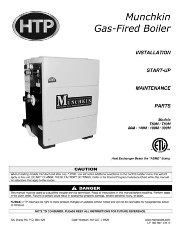
MunchkinGas-Fired 0M / T80M80M / 140M / 199M / 399MHeat Exchanger Bears the “ASME” StampWhen installing models manufactured after July 7, 2008, you will notice additional selections on the control installer menu that will notapply to this unit. DO NOT CHANGE THESE FACTORY SETTINGS. Refer to the Control Program Reference Chart within this manualfor selections that apply to this model.This manual must be used by a qualified installer/service technician. Read all instructions in this manual before installing. Perform stepsin the given order. Failure to comply could result in substantial property damage, severe personal injury, or death.NOTICE: HTP reserves the right to make product changes or updates without notice and will not be held liable for typographical errorsin literature.NOTE TO CONSUMER: PLEASE KEEP ALL INSTRUCTIONS FOR FUTURE REFERENCE.120 Braley Rd. P.O. Box 429East Freetown, MA 02717-0429www.htproducts.comLP-185 Rev. 9.9.14
2IF THE INFORMATION IN THIS MANUAL IS NOT FOLLOWED EXACTLY, A FIRE OR EXPLOSION MAY RESULT, CAUSINGPROPERTY DAMAGE, PERSONAL INJURY, OR LOSS OF LIFE. DO NOT STORE GASOLINE OR OTHER FLAMMABLE VAPORSAND LIQUIDS IN THE VICINITY OF THIS OR ANY OTHER BOILER.WHAT TO DO IF YOU SMELL GAS Do not try to light any appliance.Do not touch any electrical switch.Do not use any phone in your building.Immediately call your gas supplier from a neighbor’s phone. Follow the gas supplier’s instructions.If you cannot reach your gas supplier, call the fire department. Installation and service must be provided by a qualified installer,service agency, or the gas supplier.LP-185 Rev. 9.9.14
3The following defined terms are used throughout this manual to bring attention to the presence of hazards of various risklevels, or to important product information.DANGER indicates an imminently hazardous situation which, if not avoided, will result in death or serious injury.WARNING indicates a potentially hazardous situation which, if not avoided, could result in death or serious injury.CAUTION indicates a potentially hazardous situation which, if not avoided, may result in minor or moderate injury.CAUTION used without the safety alert symbol indicates a potentially hazardous situation which, if not avoided, may result in propertydamage.FOREWORDThis manual is intended to be used in conjunction with other literature provided with the MC Series Gas-Fired Boiler. This includes allrelated control information. It is important that this manual, all other documents included with this system, and additional publicationsincluding the National Fuel Gas Code, ANSI Z223.1-2002, be reviewed in their entirety before beginning any work.Installation should be made in accordance with the regulations of the Authority Having Jurisdiction, local code authorities, and utilitycompanies which pertain to this type of water heating equipment.Authority Having Jurisdiction (AHJ) – The Authority Having Jurisdiction may be a federal, state, local government, or individual suchas a fire chief, fire marshal, chief of a fire prevention bureau, labor department or health department, building official or electricalinspector, or others having statutory authority. In some circumstances, the property owner or his/her agent assumes the role, and atgovernment installations, the commanding officer or departmental official may be the AHJ.NOTE: HTP, Inc. reserves the right to modify product technical specifications and components without prior notice.FOR THE INSTALLERThis manual must only be used by a qualified heating installer/service technician. Read all instructions in this manual before installing.Perform steps in the order given. Failure to comply could result in severe personal injury, death or substantial property damage.This boiler must be installed by qualified and licensed personnel. The installer should be guided by the instructions furnished with theboiler, and with local codes and utility company requirements. In the absence of local codes, preference should be given to the NationalFuel Gas Code, ANSI Z223.1 – latest edition.INSTALLATIONS MUST COMPLY WITH:Local, state, provincial, and national codes, laws, regulations and ordinances.The latest version of the National Fuel Gas Code, ANSI Z223.1, from American Gas Association Laboratories, 8501 East PleasantValley Road, Cleveland, OH 44131.In Canada – CGA No. B149 (latest version), from Canadian Gas Association Laboratories, 55 Scarsdale Road, Don Mills, Ontario,Canada M3B 2R3. Also, Canadian Electrical Code C 22.1, from Canadian Standards Association, 5060 Spectrum Way, Suite 100,Mississauga, Ontario, Canada L4W 5N6.Code for the installation of Heat Producing Appliances (latest version), from American Insurance Association, 85 John Street, NewYork, NY 11038.LP-185 Rev. 9.9.14
4The latest version of the National Electrical Code, NFPA No. 70.NOTE: The gas manifold and controls met safe lighting and other performance criteria when undergoing tests specified in ANSIZ21.10.3 – latest edition.The hydronic supply and return connections of these products are for installation in closed loop systems ONLY! Use of thisproduct in any manner other than described in this manual may result in premature product failure, substantial property damage, severepersonal injury, or death. Damage or failure of this product (or the system in which it is installed) due to unauthorized use IS NOTCOVERED BY WARRANTY.IMPORTANTIn accordance with Section 325 (f) (3) of the Energy Policy and Conservation Act, HTP, Inc. has provided this boiler withmultiple features designed to save energy by reducing the boiler water temperature as heating load decreases.These features include: A modulating combustion system that adjusts firing rate based on heat demand. Adjustment of boiler set point based on inferred heat load as determined by an outdoor sensor. The outdoor sensoris supplied by HTP, Inc. with this boiler. This boiler does not include a standing pilot. This boiler is designed and shipped to assure the highest efficiency operation possible. Such high efficiency isachieved by limiting heating circuit water temperature to 140 F when there is no anticipated heat load, based uponthe outdoor sensor and the Outdoor Reset Curve (sensor response curve) in the boiler software. This feature may be over-ridden as described below in specific installations: The boiler control is equipped with an outdoor sensor override for use with building management systems or incascaded systems (for systems with total input of 300,000 BTU/hr or greater).See statement below for an important notice on the use of the override.IMPORTANTIn accordance with Section 325 (f) (3) of the Energy Policy and Conservation Act, this boiler is equipped with a feature thatsaves energy by reducing the boiler water temperature as the heating load decreases. This feature is equipped with anoverride which is provided primarily to permit the use of an external energy management system that serves the samefunction. THIS OVERRIDE MUST NOT BE USED UNLESS AT LEAST ONE OF THE FOLLOWING CONDITIONS IS TRUE: An external energy management system is installed that reduces the boiler water temperature as the heating loaddecreases. This boiler is not used for space heating. This boiler is part of a modular or multiple boiler system having a total input of 300,000 BTU/hr or greater. This boiler is equipped with a tankless coil.TABLE OF CONTENTSPART 1 – GENERAL SAFETY INFORMATION . 7A. PRECAUTIONS . 7B. IMPROPER COMBUSTION . 7C. GAS . 7D. WHEN SERVICING THE BOILER . 7E. BOILER SYSTEM . 8F. WATER CHEMISTRY* . 8G. WINTERIZING . 8PART 2 – BEFORE YOU START . 8A. WHAT’S IN THE BOX . 8B. HOW THE BOILER OPERATES. 9C. OPTIONAL EQUIPMENT . 10LP-185 Rev. 9.9.14
5PART 3 – PREPARE BOILER LOCATION . 10A. BEFORE LOCATING THE BOILER . 10B. LEVELING . 14C. CLEARANCES FOR SERVICE ACCESS . 15D. RESIDENTIAL GARAGE, CLOSET, AND ALCOVE INSTALLATIONS . 15E. EXHAUST VENT AND INTAKE PIPE . 15F. PREVENT COMBUSTION AIR CONTAMINATION . 16G. REMOVING AN EXISTING BOILER FROM AN EXISTING COMMON VENT SYSTEM . 16PART 4 – PREPARE BOILER . 17A. REMOVE BOILER FROM PACKAGING . 17B. WALL MOUNTING CONSIDERATIONS . 17C. WALL MOUNTING INSTRUCTIONS . 17PART 5 – BOILER PIPING . 18A. GENERAL PIPING INFORMATION . 18B. RELIEF VALVE . 19C. SEPARATE LOW WATER CUTOFF . 19D. BACKFLOW PREVENTER . 20E. SYSTEM WATER PIPING METHODS . 20F. CIRCULATORS. 20G. HYDRONIC PIPING WITH CIRCULATORS, ZONE VALVES, AND MULTIPLE BOILERS . 20H. CIRCULATOR SIZING . 21I. ZONING WITH ZONE VALVES. 23J. ZONING WITH CIRCULATORS . 23K. MULTIPLE BOILERS . 23L. FILL AND PURGE HEATING SYSTEM . 23M. PIPING DETAILS . 24PART 6 – PIPING WITH OPTIONAL VISION 1 SYSTEM . 31A. VISION 1 SYSTEM PIPING . 31B. ZONING WITH ZONE VALVES USING VISION 1 . 31C. ZONING WITH CIRCULATORS USING VISION 1 . 31D. PIPING DETAILS WITH THE VISION 1 SYSTEM . 32PART 7 – VENTING, COMBUSTION AIR, AND CONDENSATE REMOVAL . 42A. GENERAL . 42B. APPROVED MATERIALS FOR EXHAUST VENT AND INTAKE PIPE . 42C. REQUIREMENTS FOR INSTALLATION IN CANADA . 43D. EXHAUST VENT AND INTAKE PIPE LOCATION. 431. DETERMINE EXHAUST VENT LOCATION. 432. DETERMINE INTAKE PIPE LOCATION . 44E. EXHAUST VENT AND INTAKE PIPE SIZING . 45G. LONGER VENT RUNS . 45H. EXHAUST VENT AND INTAKE PIPE INSTALLATION . 46LP-185 Rev. 9.9.14
6I. DIAGRAMS FOR SIDEWALL VENTING . 48J. DIAGRAMS FOR VERTICAL VENTING . 50PART 8 – GAS PIPING . 51A. GAS CONNECTION . 51B. GAS PIPING . 52C. CHECK INLET GAS PRESSURE . 52D. GAS VALVE . 53PART 9 – FIELD WIRING . 54A. INSTALLATION MUST COMPLY WITH: . 54B. FIELD WIRING. 54C. LINE VOLTAGE WIRING. 54D. THERMOSTAT . 54PART 10 – FIELD WIRING – VISION 1 OPTION . 57PART 11 – START-UP PREPARATION. 58A. CHECK/CONTROL WATER CHEMISTRY . 58B. FREEZE PROTECTION (WHEN USED) . 59C. FILL AND TEST WATER SYSTEM . 59D. PURGE AIR FROM WATER SYSTEM . 59E. CHECK FOR GAS LEAKS . 60F. CHECK THERMOSTAT CIRCUIT(S) .
An external energy management system is installed that reduces the boiler water temperature as the heating load decreases. This boiler is not used for space heating. This boiler is part of a modular or multiple boiler system having a total input of 300,000 BTU/hr or greater. This boiler is equipped with a tankless coil. TABLE OF CONTENTS