Transcription
COMPONENT MAINTENANCE MANUALFORSANDEL SN3500 EHSI Navigation DisplayDocument No. 82005-0133Revision D, February 1, 2010SANDEL AVIONICS, INC.2401 Dogwood WayVista, CA 92081Telephone: (760) 727-4900Facsimile: (760) 727-4899www.sandel.comPROPRIETARY DATASANDEL AVIONICS proprietary rights are included in the information disclosed herein. Recipient byaccepting this document agrees that neither this document nor the information disclosed herein nor anypart thereof shall be reproduced or transferred to other documents or used or disclosed to others formanufacturing or for any other purpose except as specifically authorized in writing by SANDELAVIONICS.
REVISION SHEETREVDatePagesPara.DFebruary 1, 20109-11AllA/R 1108 Added Section 5. Field replacement ofDiffuser WindowCJune 24, 20097-8AllA/R 1077 Added section 4. Field u-jointreplacement.BNov 20, 2007434-6AllA/R 941; Added Lamp Kit part number; updatedfor Mod 1 LED backlight;Updated lamp housing figures for better clarity.AllAllA/R 855; Initial ReleaseASep 14, 200682005-0133-D SN3500 CMMDESCRIPTION OF CHANGESSandel Avionics ProprietaryPage 2 of 10Use or disclosure of data on this page is subject to the proprietary notice on page 1 of this document.
TABLE OF CONTENTS1.APPLICABLITY . 42.UPLOADING SYSTEM SOFTWARE AND DATABASES . 43.LAMP REPLACEMENT PROCEDURE . 44.U-JOINT REPLACEMENT PROCEDURE. 75.DIFFUSER WINDOW REPLACEMENT PROCEDURE. 982005-0133-D SN3500 CMMSandel Avionics ProprietaryPage 3 of 10Use or disclosure of data on this page is subject to the proprietary notice on page 1 of this document.
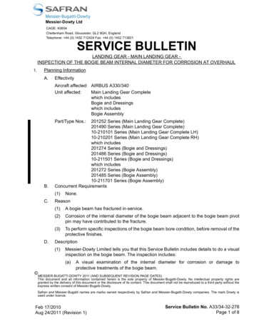
1. APPLICABLITYThis document is applicable to maintenance for continued airworthiness of Sandel SN3500EHSI Navigation display:Unit part number:SN3500-xxx, Software revision 1.00 or later2. UPLOADING SYSTEM SOFTWARE AND DATABASESSystem software is released via SIL (Service Information Letter) posted on the Sandelwebsite. The SIL contains links to the software and the related software installation filesnecessary to load the software. Database updates are available for purchase via the Sandelwebsite. The database information site also contains up-to-date links to database downloadinstructions.The SIL's and Database update information can be found at:"Support".3.www.sandel.com underLAMP REPLACEMENT PROCEDUREField lamp replacement applies to part number SN3500-xxx, serial numbers less than 2000without Mod Level 1 LED light source [the Mod level is shown on the lower portion of the TSOlabel]. Use the following eleven step procedure to replace the lamp using Sandel Lamp Kitpart number 90130-LK. SN3500-xxx Mod Level 1 LED light source is not field serviceable.Step 1Step 24 ScrewsFig. 1: Place SN3500 unit onto a grounded bencharea. Remove 4 flat head screws that hold the lampmodule.82005-0133-D SN3500 CMM2 ScrewholesFig. 2: Remove Lamp Module and carefully disconnectlamp terminals. Either of the 2 screw holes can be usedto aide module removal. Insert a 4-40 screw as a handleand pull module out.Sandel Avionics ProprietaryPage 4 of 10Use or disclosure of data on this page is subject to the proprietary notice on page 1 of this document.
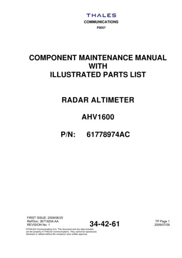
Step 3Step 4SaveDiscardFig. 4: Remove screw, lamp bracket, lamp and spacer.Discard lamp and spacer. Lamp Contains Mercury,Dispose According to Local, State or Federal Laws.Save bracket and screw for replacement lamp set.Fig. 3: Place lamp module onto flat surface.Step 5Step 6Lamp Assy84015Fig. 5: Remove lamp and shimfrom protective packaging. Do nottouch lamp glass with bare skin!This can significantly reduce lamplife. Ensure lamp is clean and freefrom dirt or dust. If cleaning isrequired, use isopropyl alcohol anda clean cotton swab.82005-0133-D SN3500 CMMStep 7Red stripewireFig. 6: Orient the lamp wire with redstripe as shown. Assemble new lamp,spacer, existing bracket and screw intolamp module as shown.Sandel Avionics ProprietaryFig. 7: Ensure lamp is fullyseated into lamp housing. Torquepan head screw until snug.Page 5 of 10Use or disclosure of data on this page is subject to the proprietary notice on page 1 of this document.
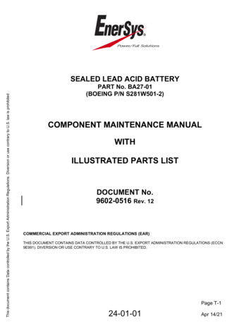
Step 8TerminalCoversFig. 8: Reconnect the lampterminals to mating terminals insideunit lamp pocket. Ensure terminalcovers are completely engagedand completely cover theconnected terminals. Thesecovers prevent high voltageshorting inside the unit.Step 11Step 9WiresinsideboxFig. 9: Ensure the lamp wires aresecurely seated inside the plasticwire box. Ensure the lamp wires arenot touching the circuit cards or rearfan surface.Step 10Fig. 10: Fully seat lamp moduleinto unit lamp pocket. Fasten andtorque flat head screws untilsnug.SOFTWARE RESET:Reset the lamp-hours counter in the SN3500 byentering the BRT/AUDIO maintenance page, in EditMode. Select “Lamp Hours/Cycles” using thearrow buttons. Press the “Reset” softkey to reset.82005-0133-D SN3500 CMMSandel Avionics ProprietaryPage 6 of 10Use or disclosure of data on this page is subject to the proprietary notice on page 1 of this document.
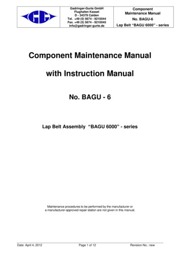
4.U-JOINT REPLACEMENT PROCEDUREField U joint replacement applies to part number SN3500-xxx. Replacement U-joints, Sandelpart number 90253-01 may be ordered from Sandel.Step 1Step 2Fig. 1: Place SN3500 unit onto a grounded bencharea. Remove 12 ea 4-40 X .25 flat head machinescrews securing side covers to unit. Remove sidecoversStep 3Fig. 2: Rotate Heading and Course knobs to expose UJoint retaining setscrews. Using 0.050” hex wrench,loosen U-Joint retaining setscrews. (left and right handsides are symmetric)Step 4Fig. 3: Remove Heading and Course Knobs thrufront of bezel, disengage U-Joints from EncoderShafts and remove from unit.82005-0133-D SN3500 CMMFig. 4:1. Apply Thread Locker (Loctite 222, or eq.) tothreads of replacement U-Joint retainingsetscrews.2. Align U-Joints to Encoder Shafts and install intounit, leaving .10” gap between rear of U-Jointand face of Encoder (see Fig. 6).3. Reinstall Heading and Course Knobs (ensuringproper orientation, see Fig. 5), thru bezel, intosockets of replacement U-Joints. Space knobsto leave .06” gap between Knobs and face ofbezel (see Fig. 6).4. Align U-Joint setscrews to flats on Encoder andKnob Shafts and tighten firmlySandel Avionics ProprietaryPage 7 of 10Use or disclosure of data on this page is subject to the proprietary notice on page 1 of this document.
Step 4 (cont.)Step 4 (cont.)Fig. 5: Ensure correct orientation of Heading andCourse Knobs.Step 5Fig. 6: Space knobs to leave .06 gap between face ofbezel and knobs, .10” gap between rear of U-Jointsand faces of Encoders.Step 6Verify Encoder operation:1. Rotate Heading and Course Knobs through360º, ensuring that mechanism does notbind.2. At each detent position, push and releaseknob, ensuring that encoder push buttonfunction operates smoothly, withoutsticking.3. If improper function is noted at any position,loosen setscrews and reposition U-Jointslightly to alleviate condition. Maintain .06gap between knob and bezel.Fig. 7: Reinstall Side Covers to SN3500. Install 12 X 440 Flat Head Machine Screws. Torques screws to5-7inch-lbs.82005-0133-D SN3500 CMMSandel Avionics ProprietaryPage 8 of 10Use or disclosure of data on this page is subject to the proprietary notice on page 1 of this document.
5.DIFFUSER WINDOW REPLACEMENT PROCEDUREField replacement of Diffuser Window applies to part number SN3500-xxx. Replacement displaywindows, Sandel part number 63034 may be ordered from Sandel.Step 1Step 2Fig. 1: Place SN3500 unit onto a groundedbench area. Carefully pry heading and courseknob caps from encoder knobs using a small,flat blade screw driver or similar. Loosenencoder knob collets using a flat blade screwdriver and remove encoder knobs from encodershafts.Step 3Fig. 2 Remove 6 ea flat head machine screws, 2-56X .125 retaining bezel to actuator housing. Holdbezel in place to prevent shifting of retainedcomponents.Step 4Fig. 3: Carefully lift Bezel and Diffuser Windowfrom unit. Do not remove or shift Fresnel lens.Remove existing window from unit.82005-0133-D SN3500 CMMFig. 4: Align replacement window to switch actuatorsand place onto Fresnel lens on face of unit. Ensure thatDiffuser Window and Fresnel Lens are properly locatedand have not shifted during procedure.Sandel Avionics ProprietaryPage 9 of 10Use or disclosure of data on this page is subject to the proprietary notice on page 1 of this document.
Step 5Step 6Fig. 5: Carefully reinstall Bezel onto ActuatorHousing. Ensure that the machined lip in DiffuserWindow engages Bezel opening and that Bezelfully seats. If necessary, loosen (but do notremove) screws at bottom corners of unit to allowMenu Actuator and USB socket to “float” to facilitateinstallation. Secure Bezel using 6 Ea Flat HeadMachine Screws, 2-56 X .125. Re-torque cornerscrews, if loosened.Fig. 6: Place encoder knobs over encoder shafts.Leave approximately 0.06” (1.5mm) gap betweenback of encoder knob and face of bezel. Tightenencoder knob collets using flat blade screw driver.Verify knob operation by rotating knob and pushingin knob. Detent in knob push should be detectableand knob should not contact bezel.Whendepressed, verify gap dimension by slipping a pieceof paper between the knob and the bezel (paper isapproximately 0.005” [0.1mm]). The paper shouldfit easily.Reinstall encoder knob caps into encoder knobs.Ensure proper location of heading and course caps.Step 7Verify installation:1. Ensure that all affected components areinstalled.2. Ensure that Bezel is fully seated.3. Ensure that Bezel retaining screws aresecurely installed.4. Ensure that all Switch Actuators operatefreely, without binding.5. Ensure that Encoder Knobs are properlyinstalled, with .060 gap between back ofknob and face of Bezel and that encoderswitches actuate freely.82005-0133-D SN3500 CMMSandel Avionics ProprietaryPage 10 of 10Use or disclosure of data on this page is subject to the proprietary notice on page 1 of this document.
82005-0133-D SN3500 CMM Sandel Avionics Proprietary Page 2 of 10 Use or disclosure of data on this page is subject to the proprietary notice on page 1 of this document. REVISION SHEET REV Date Pages Para. DESCRIPTION OF CHANGES D February 1, 2010 9-11 All A/R 1108 Added Section 5. Field replacement of Diffuser Window