Transcription
Boiler Basics, Operation andMaintenanceCourse No: M08-009Credit: 8 PDHElie Tawil, P.E., LEED APContinuing Education and Development, Inc.22 Stonewall CourtWoodcliff Lake, NJ 07677P: (877) 322-5800info@cedengineering.com
Addendum SheetBoiler Basics, Operation and MaintenanceCourse # M08-009ADDENDUM SHEET FOR BOILER BASICS, OPERATION AND MAINTENANCECOURSE # M08-009The modifications listed in this addendum sheet apply to Chapter 9 of the Naval Education andTraining Professional Development and Technology Center “Boilers” NAVEDTRA 14265Atraining course.Corrections as of July, 2021:To prevent compatibility issues, and to ensure that the content of this document is accessible in itsentirety, the interactive educational clips that are part of the original document have been disabled.As a result, the following features have been disabled: Audio and video clips, with italicized instructions of where to click to activate it. Popup boxes displaying the appropriate definition of bold and italicized glossary termswithin the text. Correct answer indicator functionality for end of chapter review questions.
Chapter9BoilersTopics1.0.0Steam Generation Theory2.0.0Boiler Fittings and Accessories3.0.0Types of Boilers4.0.0Boiler Design Requirements5.0.0Automatic Controls6.0.0Instruments and Meters7.0.0Boiler Water Treatment and Cleaning8.0.0Cleaning Boiler Firesides and Watersides9.0.0Boiler MaintenanceTo hear audio, click on the box.OverviewA boiler is an enclosed vessel in which water is heated and circulated, either as hot wateror steam, to produce a source for either heat or power. A central heating plant may haveone or more boilers that use gas, oil, or coal as fuel. The steam generated isused to heatbuildings, provide hot water, and provide steam for cleaning, sterilizing, cooking, andlaundering operations. Small package boilers also provide steam and hot water for smallbuildings.A careful study of this chapter can help you acquire useful knowledge of steam generation,types of boilers pertinent to Seabee operations, and various fittings commonly found onboilers. The primary objective of this chapter is to lay the foundation for you to developskill in the operation, maintenance, and repair of boilers.NAVEDTRA 14265A9-1
ObjectivesWhen you have completed this chapter, you will be able to do the following:1. State the steam generation theory.2. Describe boiler design requirements.3. Describe the different types of boilers.4. Describe the different types of boiler fittings and accessories.5. Identify the automatic controls associated with boilers.6. Describe the different types of instruments and meters.7. Describe the procedures associated with boiler water treatment and cleaning.8. Describe the procedures for cleaning boiler firesides and watersides.9. Describe the procedures associated with boiler maintenance.PrerequisitesNoneNAVEDTRA 14265A9-2
This course map shows all of the chapters in Utilitiesman Basic. The suggested trainingorder begins at the bottom and proceeds up. Skill levels increase as you advance on thecourse map.Utilities Equipment and MaintenanceAir ConditioningRefrigerationHeating SystemsUSteam Distribution SystemsTBoilersSewage Disposal, Field Sanitation, andWater TreatmentBPrime Movers, Pumps, andCompressorsAPlumbing FixturesSPiping System Layout and PlumbingAccessoriesIStructural Openings and Pipe MaterialCFundamentals of Water DistributionBasic Math, Electrical, and PlumbingOperationsPlans, Specifications, and ColorCodingFeatures of this ManualThis manual has several features which make it easier to use online. Figure and table numbers in the text are italicized. The figure or table is eithernext to or below the text that refers to it. The first time a glossary term appears in the text, it is bold and italicized. Whenyour cursor crosses over that word or phrase, a popup box displays with theappropriate definition. Audio and video clips are included in the text, with an italicized instruction tellingyou where to click to activate it. Review questions that apply to a section are listed under the Test Your Knowledgebanner at the end of the section. Select the answer you choose. If the answer iscorrect, you will be taken to the next section heading. If the answer is incorrect, youwill be taken to the area in the chapter where the information is forNAVEDTRA 14265A9-3
review. When you have completed your review, select anywhere in that area toreturn to the review question. Try to answer the question again. Review questions are included at the end of this chapter. Select the answer youchoose. If the answer is correct, you will be taken to the next question. If the answeris incorrect, you will be taken to the area in the chapter where the information is forreview. When you have completed your review, select anywhere in that area toreturn to the review question. Try to answer the question again.NAVEDTRA 14265A9-4
1.0.0 STEAM GENERATION THEORYTo acquaint you with some of the fundamentals underlying the process of steam operation,suppose that you set an open pan of water on the stove and turn on the heat.You findthat the heat causes the temperature of the water to increase and, at the same time, toexpand in volume. When the temperature reaches the boiling point (212 F or 100 C atsea level), a physical change occurs in the water; the water starts vaporizing. When youhold the temperature at the boiling point long enough, the water continues to vaporizeuntil the pan is dry. A point to remember is that the temperature of water does not increasebeyond the boiling point. Even if you add more heat after the water starts to boil, thewater cannot get any hotter as long as it remains at the same pressure.Now suppose you place a tightly fitting lid on the pan of boiling water. The lid preventsthe steam from escaping from the pan and this results in a buildup of pressure inside thecontainer. However, when you make an opening in the lid, the steam escapes at the samerate it is generated. As long as water remains in the pan and as long as the pressureremains constant, the temperature of the water and steam remains constant and equal.The steam boiler operates on the same basic principle as a closed container of boilingwater. By way of comparison, it is as true with the boiler as with the closed container thatsteam formed during boiling tends to push against the water and sides of the vessel.Because of this downward pressure on the surface of the water, a temperature in excessof 212 F is required for boiling. The higher temperature is obtained simply by increasingthe supply of heat; therefore, the rules you should remember are as follows:1. All of the water in a vessel, when held at the boiling point long enough, will changeinto steam. As long as the pressure is held constant, the temperature of the steamand boiling water remains the same.2. An increase in pressure results in an increase in the boiling point temperature ofwater.A handy formula with a couple of fixed factors will prove this theory. The square root ofsteam pressure multiplied by 14 plus 198 will give you the steam temperature. When youhave 1 psig (pounds per square inch gauge) of steam pressure, the square root is onetimes 14 plus 198 which equals 212 F which is the temperature that the water will boil at1 psig.The equation for figuring out the steam temperature is:Steam Pressure x 14 198 Steam TemperatureLet P Steam PressureLet T Steam TemperatureExample 1:x 14 198 212Example 2:100 x 14 198 33810 x 14 198 338140 198 338NAVEDTRA 14265A9-5
There are a number of technical terms used in connection with steam generation. Someof these commonly used terms you should know are as follows: Degree is defined as a measure of heat intensity. Temperature is defined as a measure in degrees of sensible heat. The termsensible heat refers to heat that can be measured with a thermometer. Heat is a form of energy measured in British thermal units (BTU). One Btu is theamount of heat required to raise 1 pound of water 1 degree Fahrenheit at sea level. Steam means water in a vapor state. Dry saturated steam is steam at thesaturation temperature corresponding to pressure, and it contains no water insuspension. Wet saturated steam is steam at the saturation temperaturecorresponding to pressure, and it contains water particles in suspension. The quality of steam is expressed in terms of percent. For instance, if a quantity ofwet steam consists of 90 percent steam and 10 percent moisture, the quality of themixture is 90 percent. Superheated steam is steam at a temperature higher than the saturationtemperature corresponding to pressure. For example, a boiler may operate at 415psig (pounds per square inch gauge). The corresponding saturation temperaturefor this pressure is 483 F, and this will be the temperature of the water in the boilerand the steam in the drum. This steam can be passed through a super-heaterwhere the pressure remains about the same, but the temperature will be increasedto some higher figure.Test your Knowledge (Select the Correct Response)1.At what temperature Fahrenheit does water reach the boiling point?A.B.C.D.200 212 232 275 NAVEDTRA 14265A9-6
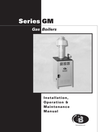
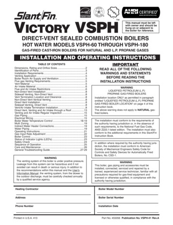
2.0.0 BOILER FITTINGS and ACCESSORIESA sufficient number of essential boiler fittings (Figure 9-1) and accessories are discussedin this section to provide a background for further study. As a reminder, and in case youshould run across some unit or device not covered here, check the manufacturer'smanual for information on the details of its construction and method of operation.Figure 9-1-Boiler fittings.The term "fittings" includes various control devices on the boiler. Fittings are vitallyimportant to the economy of operation and safety of personnel and equipment. You mustunderstand fittings if you are to acquire skill in the installation, operation, and servicingof steam boilers.All boilers require boiler fittings to operate safely. The American Society of MechanicalEngineers (ASME) requires all boiler fittings to be made of materials that withstand thepressure and temperatures that boilers are subject to. All of the boiler fittings discussedare important and must be operated and maintained properly to operate a boiler safely.2.1.0 Air CockAn air cock is located in the uppermost steam space of a boiler, as shown in Figure 9-2.This design allows for air to enter and escape during filling and draining of the boiler.Before firing a cold boiler with no steam pressure, open the air cock to allow air toNAVEDTRA 14265A9-7
escape during the heating of the water.When steam begins to come out of the aircock piping, close the valve.2.2.0 Chimneys, Draft Fans, andBreechingsChimneys are necessary for discharging theproducts of combustion at an elevation highenough to comply with health requirementsand to prevent a nuisance because of lowflying smoke, soot, and ash. A boiler needsa draft to mix air correctly with the fuelsupply and to conduct the flue gasesthrough the complete setting. The airnecessary for combustion of fuel cannot besupplied normally by a natural draft.Therefore, draft fans may be used to ensurethat the air requirements are properlyattained.Figure 9-2 - Aircock.Two types of draft fans used on boilers are forced-draft and induced-draft fans. They aredamper controlled and usually are driven by an electric motor.The forced draft fan forces air through the fuel bed, or fuel oil burner, and into the furnaceto supply air for combustion. The induced draft fan draws gases through the setting, thusfacilitating their removal through the stack. Breechings (see Item 1 in Figure 9-1) areused to connect the boiler to the stack. They are usually made of sheet steel with provisionfor expansion and contraction. The breeching may be carried over the boilers, in back ofthe setting, or even under the boiler room floor. Keep breechings as short as possible andfree from sharp bends and abrupt changes in area. The cross- sectional area should beapproximately 20 percent greater than that of the stack to keep draft loss to a minimum.A breeching with a circular cross section causes less draft loss than one with a rectangularor square cross section.2.3.0 Blowdown ValvesBlowdown valves on boilers are located onthe water column and on the lowest point ofthe water spaces of the boiler (Figure 9-3).The blowdown valves on a boiler installed atthe bottom of each water drum and headerare used to remove scale and other foreignmatter that have settled in the lowest part ofthe water spaces. Boilers are also blowndown to control concentration of dissolvedand suspended solids in boiler water. Thewater column blowdown permits removal ofscale and sediments from the water column.Additionally, some boilers have what is calleda surface blowdown. The surface blowdownis located at the approximateNAVEDTRA 14265A9-8
water level so as to discharge partial steam and water. The surface blowdown removesfoaming on the top of the water surface and any impurities that are on the surface of the water.2.4.0 Fusible PlugsFusible plugs are used on some boilers toprovide added protection against low water.They are constructed of bronze or brasswith a tapered hole drilled lengthwisethrough the plug. They have an even taperfrom end to end. This tapered hole is filledwith a low-melting alloy consisting mostly oftin. There are two types of fusible plugsfire actuated and steam actuated.The fire-actuated plug is filled with an alloyof tin, copper, and lead with a melting pointof 445 F to 450 F. It is screwed into the shellat the lowest permissible water level. Oneside of the plug is in contact with theFigure 9-4 - Fusible plug.fire or hot gases, and the other side is incontact with the water (Figure 9-4). As longas the plug is covered with water, the tindoes not melt. When the water level drops below the plug, the tin melts and blows out.Once the core is blown out, a whistling noise will warn the operator. The boiler then mustbe taken out of service to replace the plug.The steam-actuated plug is installed on the end of a pipe outside the drum. The other endof the pipe, which is open, is at the lowest permissible water level in the steam drum. Avalve is usually installed between the plug and the drum. The metal in the plug melts at atemperature below that of the steam in the boiler. The pipe is small enough to preventwater from circulating in it. The water around the plug is much cooler than the water in theboiler as long as the end of the pipe is below the water level. However, when the waterlevel drops below the open end of the pipe, the cool water runs out of the pipe and steamheats the plug. The hot steam melts and blows the tin out, allowing steam to escape fromthe boiler warning the operator. This type of plug can be replaced by closing the valve inthe piping. It is not necessary to take the boiler out of service to replace the plug.Fusible plugs should be renewed regularly once a year. Do NOT refill old casings withnew tin alloy and use again. ALWAYS USE A NEW PLUG.2.5.0 Water ColumnA water column is a hollow vessel having two connections to the boiler (Figure 9-5). Watercolumns come in many more designs than the two shown in Figure 9-5; however, they alloperate to accomplish the same principle. The top connection enters the steam drum ofthe boiler through the top of the shell or drum. The water connection enters the shell orhead at least 6 inches below the lowest permissible water level. The purpose of the watercolumn is to steady the water level in the gauge glass through the reservoir capacity ofthe column. Also, the column may eliminate the obstruction on small diameter, gaugeglass connections by serving as a sediment chamber.NAVEDTRA 14265A9-9
Figure 9-5-Typical water columns.The water columns shown are equipped with high- and low-water alarms that sounds awhistle to warn the operator. The whistle is operated by either of the two floats or the solidweights shown in Figure 9-5.2.5.1 Water Level ControlThe water level control not only automatically operates the boiler feed pump but alsosafeguards the boiler against low water by stopping the burner. Various types of waterlevel controls are used on boilers. At Seabee activities, boilers frequently are equippedwith a float-operated type, a combination float and mercury switch type, or an electrodeprobe type of automatic water level control. Each of these types is described below.The float-operated type of feedwater control, similar in design to the feedwater controlshown in Figure 9-6, is attached to the water column. This control uses a float, an arm,and a set of electrical contacts. As a low-water cutoff, the float rises or lowers with thewater level in an enclosed chamber. The chamber is connected to the boiler by two lines,a setup which allows the water and steam to have the same level in the float chamber asin the boiler. An arm and linkage connects the float to a set of electrical contacts thatoperate the feedwater pump when the water lowers the float. When the water supply failsor the pump becomes inoperative and allows the water level to continue to drop, anotherset of contacts operates an alarm bell, buzzer, or whistle, and secures the burners.NAVEDTRA 14265A9-10
The combination float and mercuryswitch type of water level controlshown in Figure 9-6, Frame 1reacts to changes made within amaintained water level by breakingor making a complete control circuitto the feedwater pump. It is asimple two-position type control,havingnomodulationordifferential adjustment or setting.As all water level controllers shouldbe, it is wired independently fromthe programmer. The control ismounted at steaming water leveland consists of a pressurized float,a pivoted rocker arm, and a cradleattached mercury switch.The combination float and mercuryswitch type of water-level controlfunctions as follows: As the waterlevel within the boiler tends todrop, the float lowers.Figure 9-6 - Combination float and mercuryswitch type of feedwater control.As the float lowers, the position of the mercury switch changes. Once the float drops to apredetermined point, the mercury within the tube runs to its opposite end. This endcontains two wire leads, and when the mercury covers both contacts, a circuit is completedto energize the feedwater pump. The pump, being energized, admits water to the boiler.As the water level within the boiler rises, thefloat rises. As the float rises, the position ofthe mercury switch changes. Once the float rises to a predetermined point, the mercuryruns to the opposite end of its tube, breaking the circuit between the wire leads andsecuring the feedwater pump. The feedwater pump remains off until the water level againdrops low enough to trip the mercury switch.Because of the hazards associated with mercury, these switches are being phased out.The electrode probe type of feedwater control and low-water cutoff and the solid state(Figure 9-6, Frame 2) type of switches are replacing them. The solid state componentsare controlled by a ground wire connected to the side of the reservoir and a probe thatextends into the water column. When the water is at the acceptable level, current isavailable and the switch remains closed. When the water level drops, the current isreduced and the switch is activated thus turning on the water pump. If the water leveldrops too far down the probe, the burner cutout switch is activated and the burner will notcome on until the water reaches the appropriate level.NAVEDTRA 14265A9-11
The electrode probe type offeedwater control and low-watercutoff consists of an electrodeassembly and a water level relay(Figure 9-7). The electrodeassemblycontainsthreeelectrodes of different lengthscorresponding to high, low, andburner cutout in the boiler drum.To understand the operation ofa boiler circuit, refer to Figures9-7 and 9-8 as you read theinformation in Table 9-2.Although this information is notcomplete, it is presented here toacquaint you with the operationof the electrode type of boilerwater-level control.Figure 9-7 - Electrode type of water-levelcontrol.Figure 9-8-Typical boiler circuit.NAVEDTRA 14265A9-12
Table 9-2 - Operation of a boiler circuit.OperationActionResultsWhen the feed pumpswitch is in the autoposition.The feed pump motor isenergized.The feed pump willoperate under control ofthe water-level relay.When the water level inthe boiler reaches thelevel of electrode #3.The circuit through theelectrode is groundedand this completes thecircuit.All of the contacts labeled#6 change positions. Thethree feed pump contactsthat are normally closed,open, and contact 6-4closes which maintainsthegroundedcircuitthrough electrode #2.When the water level falls The circuit through relaybelow electrode #2.#6 will no longer begrounded because thewater is not in contactwith the electrode.This de-energizes relay#6, so all of the contactslabeled #6 return to theirnormal positions.Contacts 6-1 through 6-3close and 6-4 opens. Thefeedwaterpumpisenergized and water ispumped into the boiler.When the water levelrises again to electrode#3.The cycle continues andthe water level in theboiler is maintained.Relay #6 will energizeagain.When the water level falls Relay #5 will be debelow electrode #1.energized.Contact 5-1 will open.This action de-energizesthe entire control circuit.The boiler is now shutdown and the low-wateralarm is sounded.2.5.2 Try CocksThe purpose of the try cocks is to prove the water level in the boiler. You may see waterin the gauge glass, but that does not mean that the water level is at that position in theboiler. lf the gauge glass is clogged up, the water could stay in the glass, giving a falsereading. The try cocks, on the other hand, will blow water, steam, or a mixture of steamand water out of them when they are manually opened. When steam is discharged fromthe lowest try cock, you have a low-water condition.WARNINGWhen the water level is proved using the try cocks, personnel should stand off to the sideof the try cocks away from the discharge. The discharged steam or scalding water cancause severe burns.NAVEDTRA 14265A9-13
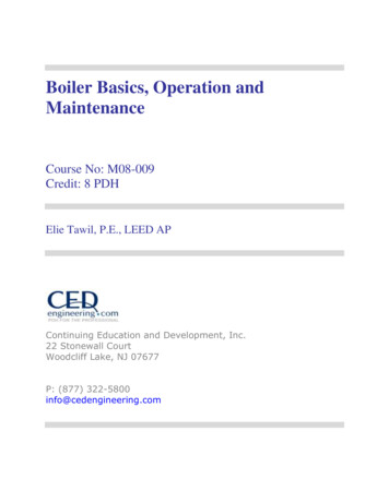
2.5.3 Gauge GlassThe gauge glass allows the boiler operator to see the water level in the boiler. Normallythere are two valves associated with the gauge glass. One valve is located at the top andone is located at the bottom of the gauge glass. These two valves, named gauge cockvalves, secure the boiler water and steam from the gauge glass. Another valve locatedin line with the gauge glass is used to blow the gauge glass down.2.6.0 Safety ValveThe safety valve shown in Figure9-9 is the most important of boilerfittings. It is designed to openautomatically to prevent pressurein the boiler from increasingbeyond the safe operating limit.The safety valve is installed in avertical position and attacheddirectly to the steam space of theboiler. Each boiler has at leastone safety valve; when the boilerhas more than 500 square feet ofheating surface, two or morevalves are required.There are several different typesof safety valves in use, but all aredesigned to open completely(POP) at a specific pressure andto remain open until a specifiedpressure drop (BLOWDOWN)has occurred.Figure 9-9 - Spring-loaded safety valve.Safety valves must close tightly, without chattering, and must remain tightly closed afterseating.To understand the difference between boiler safety valves and ordinary relief valves isimportant. The amount of pressure required to lift a relief valve increases as the valvelifts, because the resistance of the spring increases in proportion to the amount ofcompression. When a relief valve is installed on a steam drum, it opens slightly when thespecified pressure is exceeded, a small amount of steam is discharged, and then thevalve closes again. Thus a relief valve on a steam drum is constantly opening andclosing; this repeated action pounds the seat and disk and causes early failure of thevalve. Safety valves are designed to open completely at a specified pressure to overcomethis difficulty.Several different types of safety valves are used on boilers; however, they all lift on thesame general principle. In each case, the initial lift of the valve disk, or feather, is causedby static pressure of the steam acting upon the disk, or feather. As soon as the valvebegins to open, however, a projecting lip, or ring, of the larger area is exposed for thesteam pressure to act upon. The resulting increase in force overcomes the resistance ofthe spring, and the valve pops, that is, it opens quickly and completely.Because of the larger area now presented, the valve reseats at a lower pressure thanthat which caused it to lift originally.NAVEDTRA 14265A9-14
Lifting levers are provided to lift the valve from its seat (when boiler pressure is at least75 percent of that at which the valve is set to pop) to check the action and to blow awayany dirt from the seat. When the lifting lever is used, raise the valve disk sufficiently toensure that all foreign matter is blown from around the seat to prevent leakage after beingclosed.The various types of safety valves differ chiefly as to the method of applying compressionto the spring, the method of transmitting spring pressure to the feather, or disk, the shapeof the feather, or disk, andthemethodofblowdownadjustment. Detailed informationontheoperationandmaintenance of safety valvescan be found in the instructionbooksfurnishedbythemanufacturers of this equipment.2.7.0 Steam Injector FeedSystemThe steam injector is a boiler feedpump that uses the velocity andcondensation of a jet of steamfrom the boiler to lift and force ajet of water into the boiler(Figure9-10). This injection of water ismany times the weight of theoriginal jet of steam.The injector is used to someextent in boiler plants as anemergency or standby feed unit.Itdoes not feed very hot water.Under the best conditions, it canlift a stream of water having atemperature of 120 F about 14feet.Figure 9-10 - Cross-sectional view of asteam injector.The installation of an injector isnot a difficult operation becausethe unit is mounted on the side ofthe boiler. The four connections tothe injector are as follows (Figure9-11):1. The discharge line to theboiler feedwater inlet2. The steam supply line fromthe boiler3. The water overflow line4. The water supply line fromthe reservoir.NAVEDTRA 14265AFigure 9-11 - Injector piping.9-15
The controls for the injector include the following (Figure 9-11):A. Steam supply valveB. Water supply valveC. Discharge valve to the boilerD. Check valve in the discharge lineAs you might expect, some degree of skill is needed to start the injector. After the injectorbegins to operate, however, it continues automatically until shutdown by the operator.When starting the injector, first open the water supply valve (Figure 9-11B) about one fullturn. Next quickly turn the steam supply valve (Figure 9-11A) all the way open. At thispoint, steam rushes into the combining tube of the injector. As the steam speeds past thewater supply opening, it creates a suction that draws water through the opening into thecombining tube. Water and steam are now mixed together inside the injector, and thepressure opens a valve that leads to the boiler. Meanwhile, there is an excess of waterin the injector; this excess is discharged through the overflow valve. As the next step ofthe procedure, slowly turn the water supply valve (Figure 9-11B) toward the closed positionuntil the overflow stops. The overflow valve has now closed, and all of the water beingpicked up from the supply line is going into the boiler. Remember, this feedwater systemis used on boilers only as a standby method for feeding water.For the injector to operate, the water supply should not be hotter than 120 F. When severalunsuccessful attempts are made to operate the injector, it will become very hot and cannotbe made to prime. When you encounter this problem, pour cold water over the injectoruntil it is cool enough to draw water from the supply when the steam valve is opened.2.8.0 Handholes and ManholesHandholes and manholes provide maintenance personnel access into a boiler to inspectand clean it internally as needed. These handholes and manholes will be covered in depthwhen boiler maintenance is discussed later in this chapter.NAVEDTRA 14265A9-16
2.9.0 Boiler AccessoriesFigure 9-12 provides a graphic presentation of important boiler accessories. Refer to itas you study Table 9-3, which gives a brief description of each accessory, its location,and function.Figure 9-12 - Boiler accessory equipment.NAVEDTRA 14265A9-17
Table 9-3 - Boiler accessories, location, and function.ItemAccessoryLocationFunctionBoilerBoiler roomGenerate steam orhot water in a closedvessel.Main steam stopOn the steam outlet of a boilerPlace the boiler online or off line.Guard valveOn the steam outlet of a boilerdirectly following the mainsteam stop valveGuard or backup tomain steam stopvalve.Daylight (drain)valveBetween the main steam-stopvalve and the guard valveOpen only when themain steam andguard valves areclosed. Indicates ifone of the valves isleaking through.Main steam lineThe line that conveys steamfrom a boiler to all branch ordistribution lines. When asystem is supplied by a bankof boilers connected into thesame header, the line(s)conveying steam for theboiler(s) to the headerCarry steam from theboiler to the branchesor distribution lines.Root valveInstalled in branch ordistribution lines just off of themain steam lineIsolate a branch ordistribution line(serves as anemergency shutoff).Pressure regulatingvalves (PRV)Installed as close as practical(after a reducing station) to theequipment or area it servesEquipment thatrequires lowerpressure than mainsteam line pressure(coppers,dishwashers, steamchests, or turbines).Steam trapInstalled on the discharge sideof all steam heating or coolingequipment, dead ends, lowpoints, or at regular intervalsthroughout a
4.0.0 Boiler Design Requirements 5.0.0 Automatic Controls 6.0.0 Instruments and Meters 7.0.0 Boiler Water Treatment and Cleaning 8.0.0 Cleaning Boiler Firesides and Watersides 9.0.0 Boiler Maintenance To hear audio, click on the box. Overview A boiler is an enclosed vessel in which water is heated and circulated, either as hot water