Transcription
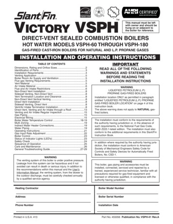
VICTORY VSPHThis manual must be leftwith owner and should behung on or adjacent tothe boiler for reference.DIRECT-VENT SEALED COMBUSTION BOILERSHOT WATER MODELS VSPH-60 THROUGH VSPH-180GAS-FIRED CAST-IRON BOILERS FOR NATURAL AND L.P. PROPANE GASESINSTALLATION AND OPERATING INSTRUCTIONSTABLE OF CONTENTSDimensions, Rating and Orifice Sizes .2Identification of Parts .3Installation Requirements .4Venting Application .5Boiler Room Air Supply and Ventilation.5Flue gas Venting Requirements.5Vent Material .5Air Intake Material .6Flue and Air Intake Restrictions .6Non-Direct Vent Installation .8Sidewall Venting, Non-Direct Vent .8Vent Termination Location and Clearance.8Non-Direct Vent Vertical Venting .8Direct Vent Installation .8Sidewall Venting, Direct Vent .8Vent/Air Intake Termination Installation.8Direct Vent, Venting and Air Intake through a Roof .13Venting and Air Intake Regular Inspection .15Gas Piping .15Electrical Wiring .15Boiler Water Temperature Control .18-19Multi Zoning .19Indirect Water Heater Connections.19Water Piping .19Operating Instructions.21Gas Input Rate Adjustment .22Boiler Control .23Status of Indicator Lights (LED’s) .23Safety Check .24Sequence of Operation.25Care and Maintenance .26General Troubleshooting Guide .27-29WARNINGThe venting system of this boiler is under positive pressure.Leakage from this system can be hazardous and if notavoided can result in death or serious injury. In addition tothe recommendations within this manual and the User’sInformation Manual, the venting system, from the blower tothe outdoor discharge, must be carefully checked annuallyby a qualified service agency.IMPORTANTREAD ALL OF THE FOLLOWINGWARNINGS AND STATEMENTSBEFORE READING THEINSTALLATION INSTRUCTIONSWARNINGLIQUEFIED PETROLEUM (L.P.)PROPANE GAS-FIRED BOILERSInstallation location ONLY as permitted in paragraphentitled "LIQUEFIED PETROLEUM (L.P.) PROPANEGAS-FIRED BOILER LOCATION" on page 4 of thisinstruction book.The above warning does not apply to NATURAL gasfired boilers.The installation must conform to the requirements ofthe authority having jurisdiction or, in the absence ofsuch requirements, to the National Fuel Gas Code,ANSI Z223.1-latest edition. The installation must alsoconform to the additional requirements in this Slant/FinInstruction Book.In addition where required by the authority having jurisdiction, the installation must conform to AmericanSociety of Mechanical Engineers Safety Code forControls and Safety Devices for Automatically FiredBoilers, No. CSD-1.WARNINGThis boiler, gas piping and accessories must beinstalled, connected, serviced and repaired by atrained, experienced service technician, familiar with allprecautions required for gas-fired equipment andlicensed or otherwise qualified, in compliance with theauthority having jurisdiction.Heating ContractorBoiler Model NumberAddressBoiler Serial NumberPhone NumberInstallation DatePrinted in U.S.A. 413Part No. 455056 Publication No. VSPH-41 Rev.A
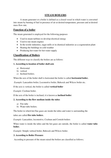
2VICTORY VSPH ModelsRATINGS AND DIMENSIONSNOTE: Height dimensions increase by11 2" and depth increases to 281 2" whencombustible floor kit is used.Figure 1. Dimensions dataBoilerModelInputBtuhNo. ofSectionsBVSPH-6060,0003A111 8"173 8"VSPH-9090,0004141 8"203 8"VSPH-120120,0005171 8"233 8"VSPH-150150,0006201 8"263 8"VSPH-180180,0007231 8"293 8"Gas Orifice SizeVictory VSPH boilerOrifice Sizes for High AltitudesIncludes 4% Reduction for Each 1000 FeetOrificeSize forSea on — Feet5000 6000 7000Orifice sizes indicated for sea level above are factory installed in boiler unless otherwise specified by the local authority. Orificetable is based on a higher heating value between 1000 Btuh and 1010 Btuh for Natural Gas (See page 20, if local higher heating value exceeds these numbers). See page 20, for burner input adjustment.
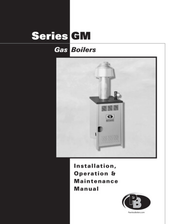
3VICTORY VSPH ModelsLOCATION AND IDENTIFICATION OF PARTSFigure 2. Location and identification of partsFigure 2a. Hydrolevel Model 3000 BoilerWater Temperature Control
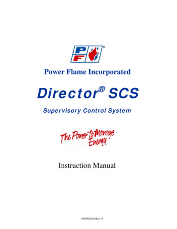
4INSTALLATION REQUIREMENTSThe installation must conform to the requirements of theauthority having jurisdiction or, in the absence of suchrequirements, to the National Fuel Gas Code, ANSI Z223.1latest edition.This installation must also conform to the additional requirements in this Slant/Fin Instruction Book.NATURAL GAS-FIRED BOILER LOCATIONProvide a level, solid foundation for the boiler. Locationshould be as near as possible to chimney or outside wall sothat the flue pipe from boiler is short and direct. (See Appendix A for vent terminal location restrictions.) The locationshould also be such that all boiler components are protectedfrom water (dripping, spraying, rain, etc.) during applianceoperation and service (circulator replacement, controlreplacement, etc.).WARNINGLIQUEFIED PETROLEUM (L.P.) PROPANE GAS-FIREDBOILER LOCATIONREQUIRES SPECIAL ATTENTIONLiquefied Petroleum (L.P.) propane gas is heavier than air.Therefore, propane boilers, piping, valves should NOT beinstalled in locations where propane leaking from defectiveequipment and piping will "pool" in a basement or otherspace below the leak.VICTORY VSPH ModelsMINIMUM CLEARANCES FROM COMBUSTIBLECONSTRUCTIONSA. Minimum clearances to the exterior surfaces of the boilershall be as follows:MINIMUM ALCOVE AND CLOSET CLEARANCESurfaceFrontRearLeft SideRight SideTopFlue Connector:Enclosed —Uninclosed —For CombustibleConstruction6"6"6"12"12"Recommendedfor Service18"18"18"24"12"6"2"6"6"B. Provide accessibility clearance of 24" on sides requiringservicing and 18" on sides used for passage.C. All minimum clearances shown above must be met. Thismay result in increased values of some minimum clearances in order to maintain the minimum clearances ofothers.D. Clearance from hot water pipes shall be 1 inch**.** At points where hot water pipes emerge from a floor, wall or ceiling,the clearance at the opening through the finished floor boards or wallor ceiling boards may be not less than 1/2 inch. Each such openingshall be covered with a plate of uncombustible material.A spark or flame from the boiler or other source may ignitethe accumulated propane gas causing an explosion or fire.Provide a level, solid foundation for the boiler. Locationshould be as near the chimney as possible so that the fluepipe from boiler to chimney is short and direct.The UNIFORM MECHANICAL CODE may be in effect inyour geographic area.The following precautions are cited by the 1994 UNIFORMMECHANICAL CODE, section 304.6:"LPG Appliances. Liquefied petroleum gas-burningappliances shall not be installed in a pit, basement orsimilar location where heavier-than-air-gas might collect.Appliances so fueled shall not be installed in an abovegrade under-floor space or basement unless such location is provided with an approved means for removal ofunburned gas."Consult Chapter 5 of the 1994 UNIFORM MECHANICALCODE for design criteria of the "approved" means forremoval of unburned gas.BOILER FOUNDATIONA. Provide a solid, level foundation, capable of supportingthe weight of the boiler filled with water, and extending atleast 2" past the jacket on all sides. See dimensions ofboilers, page 2.B. For installation on non-combustible floors only*.C. If boiler is to be located over buried conduit containingelectric wires or telephone cables, consult local codes orthe National Board of Fire Underwriters for specificrequirements.* Installation on combustible flooring allowed only with proper Combustible Floor Kit. Kit part number is printed on boiler rating plate.In no case may the boiler be installed on carpeting.Figure 3. Victory “VSPH” boiler min. clearances forcombustible construction.SAFETYKEEP THE BOILER AREA CLEAR AND FREE FROMCOMBUSTIBLE MATERIALS, GASOLINE AND OTHERFLAMMABLE VAPORS AND LIQUIDS.
5VICTORY VSPH ModelsVENTING APPLICATIONVSPH Series are sealed combustion type boilers, they maybeinstalled and vented either as a direct vent boiler which all airfor combustion is obtained directly from outside or as a nondirect vent boiler which air for combustion is taken from insidethe boiler room.VSPH boilers must be vented by proper 3" diameter stainlesssteel venting system (see “vent material” on this page) throughthe roof or sidewall.BOILER ROOM AIR SUPPLY AND VENTILATIONAn ample supply of air is required for combustion and ventilation. When buildings are insulated, caulked and weatherstripped, now or later on, direct openings to outside may berequired and should be provided. If the boiler is not near anoutside wall, air may be ducted to it from outside wall openings.Provisions for combustion and ventilation air must be made inaccordance with section 5.3, Air for Combustion and Ventilation, of the National Fuel Gas Code, ANSI Z223.1-latest edition, or applicable provisions of the local building codes. Thefollowing recommendation applies to buildings of energy-savingconstruction, fully caulked and weatherstripped.INSTALLATION IN ENCLOSED BOILER ROOM REQUIRESTWO UNOBSTRUCTED OPENINGS FOR PASSAGE OF AIRINTO THE BOILER ROOM:A. NON-DIRECT VENT INSTALLATION1. Air drawn horizontally from outdoors DIRECTLYthrough an outside wall; one louvered opening near thefloor and one louvered opening near the ceiling, each opening with a minimum FREE air passage area of 1 squareinch per 4000 Btuh of total appliances’ input.2. Air drawn horizontally through HORIZONTAL DUCTS;one opening near the floor and one opening near the ceiling, each opening with a minimum FREE air passage areaof 1 square inch per 2000 Btuh of total appliances’ input.3. Air drawn VERTICALLY from outdoors; one opening atthe floor and one opening at the ceiling, each opening witha minimum FREE air passage area of 1 square inch per4000 Btuh of total appliances’ input.4. Air drawn from inside the building; one opening nearthe floor and one opening near the ceiling, each openingwith a minimum FREE air passage area of 1 square inchper 1000 Btuh of total appliances’ input.IF BOILERS ARE INSTALLED ADJACENT TO OTHER FUELBURNING EQUIPMENT, THE AREA OF FREE OPENINGSMUST BE APPROPRIATELY INCREASED TO ACCOMMODATE THE ADDITIONAL LOAD.B. DIRECT VENT INSTALLATIONAdequate air supply should be provided to prevent overheatingof the boiler controls and boiler room. Openings for passage ofair into the boiler room for direct-vent installation must be atleast 1 2 of the openings required for the non-direct vent as mentioned above.If additional non-direct vent appliances are installed in the samespace and adequate air openings are provided for them, thereare no additional air openings required for the VSPH boiler.For both direct and non-direct installation, the following must beconsidered:- Openings must never be reduced or closed. If doors orwindows are used for air supply, they must be lockedopen.- Protect against closure of openings by snow and debris.Inspect frequently.- No mechanical draft exhaust or supply fans are to beused in or near the boiler area.- Boiler area must never be under negative pressure. Theflow of combustion and ventilating air to the boiler mustnot be obstructed.FLUE GAS VENTING REQUIREMENTSThe Victory VSPH series boiler is a high efficiency, mechanically induced draft boiler and, therefore, requires different ventingarrangements than natural draft, lower efficiency boilers.THE FOLLOWING INSTRUCTIONS MUST BE CAREFULLYREAD AND FOLLOWED IN ORDER TO AVOID ANY HAZARDOUS CONDITIONS DUE TO IMPROPER INSTALLATIONOF THE AIR INTAKE AND FLUE GAS VENTING SYSTEM.The vent piping installation MUST be in accordance with theseinstructions and with ANSI Z223.1-latest edition NATIONALFUEL GAS CODE, Part 7, Venting of Equipment. Other localcodes may also apply and must be followed. Where there is aconflict between these requirements, the more stringent caseshall apply.The use of a vent damper is NOT permitted on this boilerseries.VENT MATERIALThe vent system for direct or non-direct vent installation mustbe UL listed single wall 3” diameter AL29-4C* stainless steelmaterial. The following manufacturers’ systems are approvedfor use within a specified minimum and maximum equivalentvent length for each model. Proper adapter must be used as aconnector between Victory VSPH boilers flue collar and ventingsystem as shown below:ManufacturerType/SystemAdapter PartNo.SealantHeat-Fab. Inc.Saf-T VentNot requiredRTV 106 or DowCorning 732Heat-Fab. Inc.Saf-T VentEZ SealNot requiredNot RequiredProTech System,Inc.FasNSealFSA-HFA3Not RequiredFlex-LInternational, Inc.StaR-34SRASFA3GE-IS806Z-VentO2SVSSLA2Z-Flex, Inc.GE, RTV 106Heat-Fab Part Numbers for various items of vent system are listed inSlant/Fin Part List, Publication No. VSPH-10PL*AL29-4C is a registered Trademark of Allegheny Ludlum Corp
6When joining the various components of the above listedvent systems, the manufacturers’ instructions should beclosely followed to insure proper sealing. Use sealant specified by vent system manufacturer for sealing of pipe and fittings. See Figure 4 for proper application of vent pipe sealingfor Saf-T vent system by Heat-Fab, Inc. All vent connectionsmust be liquid and pressure tight. Flue vent system CANNOTbe cut to length. Consult manufacturer’s instructions. For HeatFab system, use slip joint connector to adjust pipe lengthsdimensions.DO NOT use plastic or galvanized flue pipe.Figure: 4 Vent Sealing Instructions(Consult vent manufacturer’s instructions.)AIR INTAKE PIPE MATERIAL3” PVC Schedule 40 or galvanized steel materials are recommended.All joints must be sealed using appropriate sealants.FLUE AND AIR INTAKE RESTRICTIONS1. Maximum allowed equivalent flue and air intake length fordifferent flue systems at different altitudes are given in thetables on page 7.2. Equivalent of flue or air intake length is sum of thestraight pipe lengths and equivalent length of elbows asshown in the table on this page.3. The vent termination is in addition to the allowed equivalent lengths.4. Minimum flue length is 2 feet.5. Flue length restriction is for both direct and non-directvent installations.VICTORY VSPH ModelsEXAMPLE: Boiler model VSPH-180 is to be installed at sealevel. The combustion air is provided by air intake pipingdirectly to the boiler (direct-vent installation). Flue pipingincludes 2 elbows and using Heat-Fab system. Air intake isPVC and includes 3 elbows.Maximum straight flue length would be 30-2x3 24 feet.Maximum straight air intake pipe would be 40-3x5 25 feet.If the air for combustion were taken from the boiler room(non-direct vent installation), still the maximum straight fluelength would be 24 feet.6.All Victory VSPH boilers are equipped with a built-incondensation drain and trap. The trap loop must befilled with water. DO NOT operate the boiler withoutfilling the trap with water to prevent flue gas dischargeinto space. The drain should extend to a floor drain orto a container which may require emptying periodically.7.The horizontal vent pipe must be sloped upward fromthe boiler at a pitch of at least 1 4" per 1 foot of run, sothat the condensate from the vent system runs to thedrain trap.8.The horizontal vent pipes must be supported with pipestraps at intervals no greater than indicated by ventpipe manufacturer’s instructions. The vertical portionvent pipe also must be supported per manufacturer’sinstructions. Support air intake piping in the samemanner as the vent pipes.9.Minimum clearances of vent pipes from combustibleconstructions must be maintained (see Page 4). Maintain minimum 1" clearance between vent pipes andPVC air intake pipes.10.Common venting with other appliances or anotherVSPH boiler is not allowed.11.DO NOT install a vent damper or similar devices invent system or on the boiler.12.Do not insulate venting system.Equivalent Length of Various 90-Degree ElbowsManufacturerHeat-Fab, Inc.Type/SystemEquivalentLength (Feet)Heat-Fab, Inc.Saf-T StandardelbowSaf-T, tight radius elbow36ProTech System, Inc.FasNseal6Flex-L International, Inc.StaR-346N/APVC, Schedule 405N/AGalvanized steel6
7VICTORY VSPH ModelsMaximum allowed flue and air intake equivalent length (Feet)forHeat-Fab Saf-T vent system (Including EZ Seal)Boiler ipingFlueAir IntakeFlueAir IntakeFlueAir IntakeFlueAir IntakeFlueAir Intake0 - 5,000 Ft. 5,000 - 7,500 540304028357,500 - 10,000 Ft.Elevation40403540304025352330Maximum allowed flue and air intake equivalent length (Feet)forFlex-L StaR-34 vent systemsBoiler ipingFlueAir IntakeFlueAir IntakeFlueAir IntakeFlueAir IntakeFlueAir Intake0 - 5,000 Ft. 5,000 - 7,500 040254023357,500 - 10,000 Ft.Elevation35403040254020351830Maximum allowed flue and air intake equivalent length (Feet)forProTech FasNSeal vent systemsBoiler ipingFlueAir IntakeFlueAir IntakeFlueAir IntakeFlueAir IntakeFlueAir Intake0 - 5,000 Ft. 5,000 - 7,500 540204018357,500 - 10,000 Ft.Elevation30402540204015351530
8VICTORY VSPH ModelsVENTING INSTALLATIONFollow the vent material manufacturer’s instructions in conjunction with these instructions for venting system installation.I.Non-Direct Vent InstallationThe air for combustion is taken from the ambient air surrounding the boiler; therefore, ample supply of air is requiredfor combustion and ventilation (see page 5.)DO NOT use this installation method if the surrounding of theboiler is contaminated. The harmful corrosive contaminationmay be from the chlorine-type detergents, cleaners, bleaches, and fabric softeners used in laundry or chlorine-basedswimming pool chemicals.An existing chimney (see Figure 8) may be used as a chasefor vertical venting. Other appliances CANNOT be ventedinto the same chimney or vent pipe with in the chimney.The vertical vent piping must terminate with a screened tee,combination of 45 elbow and a 90 screened elbow termination or a rain cap termination.II. Direct Vent InstallationAir intake piping from outside to the boiler air intake collarprovides the air for combustion. The boiler surrounding maybe contaminated with chlorine-based products such as laundry detergents.A. SIDEWALL DIRECT VENTINGA. SIDEWALL VENTING - NON-DIRECT VENTFigures 5 and 6 show typical horizontal sidewall venting. Forcombustible wall passage of vent piping, a UL listed thimblemust be used, providing the wall thickness from 3" minimumup to 12" maximum. The vent piping must terminate with ascreened tee or elbow termination facing down.CAUTION: Flue gasses exiting from the vent terminal willcondense. Building materials in the area of the vent terminalshould be protected from discoloration and degradation.Figures 9 and 10 show typical sidewall direct venting.Slant/Fin vent/air intake termination MUST be used for thismethod of installation.CAUTION: Flue gasses existing from the vent terminal willcondense. Building materials in the area of the terminalshould be protected from discoloration and degradation. Seepage 8 for vent termination location and required clearances.VENT/AIR INTAKE TERMINATION INSTALLATIONVENT TERMINATION LOCATION AND CLEARANCES1. The venting system shall terminate at least 3 feet aboveany forced air inlet located within 10 feet.1.Termination must be installed horizontally.2.Refer to Figure 11 for installation details.2. The venting system shall terminate at least 12 inchesbelow, or 12 inches horizontally from, any door, window orgravity air inlet into any building. The bottom of the ventterminal or air intake terminal shall be at least 12 inchesabove grade or the normal snow level whichever is greater.3.Wall thickness should be 3" to 12" thick4.Follow instruction for “vent termination location andclearances” explained on this page5.Cut a rectangular opening with following dimensions inthe wall.Height: 51 4"Width: 123 4"6.From outside of the wall, install outside terminationplate using 4 screws. Make sure the louvers are atleft side.7.For combustible wall a 4" galvanized pipe must beused as a wall thimble.The length of the 4" galvanized pipe should beapproximately 1" shorter than the wall thickness.8.From inside the building, fit galvanized pipe over 4"collar of the outside plate.9.From inside, fit 3" diameter air intake pipe over 3"collar located on the air box of the outside plate.3. Through the wall vents shall not terminate over publicwalkways or over areas where condensate or vapor couldcreate a nuisance or hazard or could be detrimental tothe operation of regulators, relief valves or other equipment. Minimum clearance of 4 feet horizontal distance ismaintained, from electric meters, gas meters, regulatorsand relief equipment.4. Vent termination must not be located in any confinedspace (i.e. window wells, alcoves, narrow alleys) or underany overhang or deck. Vent termination should not allowflue gas discharge towards neighbor’s windows or wherepersonal injury or property damages can occur.B. NON-DIRECT VENT - VERTICAL VENTINGFigure 7 shows typical venting through the roof. The ventpipe must pass through the ceiling, floor and the roof vertically through a 7" minimum diameter cutout. A fire stop isrequired for each ceiling and floor penetration. For roof passage, an appropriate UL listed roof flashing must be used.(text continued p.13)
9VICTORY VSPH ModelsVICTORY VSPH MODELS NON - DIRECT VENT, SIDEWALL VENTINGAll joints must be liquid and pressure tight. Use U/L listed single wall 3" dia.AL29-4C S.S.*. venting materials (See page 5).Figure 5. Non-direct vent, side wall venting.Figure 6. Non-direct vent, side wall venting.Definition of Snow Line: Knowledge of local conditions will reveal the maximum height that repeated snowfalls accumulate to.The height should be used as the SNOW LINE.* AL 29-4C IS A REGISTERED TRADEMARK OF ALLEGHENY LUDLUM CORP.
10VICTORY VSPH ModelsVICTORY VSPH MODELS- NON- DIRECT VENT, VENTING THROUGH A ROOFAll joints must be liquid and pressure tight. Use U/L listed single wall 3" dia.AL29-4C* S.S. venting materials (See page 5).Figure 7. Victory VSPH models-non-direct vent, venting through the roof* AL 29-4C IS A REGISTERED TRADEMARK OF ALLEGHENY LUDLUM CORP.
VICTORY VSPH ModelsVICTORY VSPH MODELS- NON - DIRECT VENT, UTILIZING AN EXISTINGCHIMNEY AS A CHASEAll joints must be liquid and pressure tight. Use U/L listed single wall 3" dia.AL29-4C* S.S. venting materials (See page 5).Figure 8. Victory VSPH models-non-direct vent, utilizing an existing chimney as a chase* AL 29-4C IS A REGISTERED TRADEMARK OF ALLEGHENY LUDLUM CORP.11
12VICTORY VSPH ModelsVICTORY VSPH MODELS - DIRECT VENT, SIDEWALL VENTINGAll joints must be liquid and pressure tight. Use U/L listed single wall 3" dia.AL29-4C* S.S. venting materials (See page 5).Figure 9. Direct vent, sidewall venting illustration; with straight horizontal vent.Figure 10. Direct vent, sidewall venting illustration; horizontal vent using elbows.** Definition of Snow Line: Knowledge of local conditions will reveal the maximum height that repeated snowfalls accumulate to.The height should be used as the SNOW LINE.* AL 29-4C IS A REGISTERED TRADEMARK OF ALLEGHENY LUDLUM CORP.
13VICTORY VSPH Models10.From inside, install inside termination plate using 4screws. Make sure the 4" collar on the plate, penetrateed into the galvanized pipe.11.Assemble and seal straight screened termination tothe slip joint connector.12.From outside of the building, insert vent pipe (slip jointconnector and termination assembly) through the 3"holes of the outside and inside termination plate.13.From outside of the building seal outside terminationplate to building.14.From inside, proceed with air intake and vent pipeinstallation. Follow vent manufacturer’s instructions andrestrictions mentioned on page 6 of this manual. DONOT exceed the maximum allowed equivalent lengthsgiven in tables on page 7.When joining various components of the vent system and airintake piping, proper sealant must be used (see page 6).Install horizontal vent pipe with seams on the top. Connectand seal air intake piping to air intake collar of the boiler.Adjust the air pipe support to hold air intake pipe securely(see Figure 2).Figure 11. Vent/Air Intake TerminationB. DIRECT VENT - VENTING AND AIR INTAKETHROUGH A ROOFFigure 12 shows typical vertical venting. The vent pipe mustpass through the ceiling, floor and the roof vertically through a7" minimum diameter cutout. A fire stop is required for eachceiling and floor penetration. For roof passage an appropriateUL listed roof flashing must be used.The vertical vent piping must terminate with a screenedstraight termination.The air intake terminal should be a screened 180 elbow facing down. The air intake opening must be at least 1 foot belowthe vent opening.Follow vent manufacturer’s instructions and restrictions mentioned on page 6 of this manual.DO NOT exceed the maximum allowed equivalent length givenin tables on page 7. When joining various components of thevent system and air intake piping, proper sealant must beused (see page 6).Install horizontal vent pipe with seams on the top. Connectand seal air intake piping to air intake collar of the boiler.Adjust the air pipe support to hold air intake pipe securely(See Figure 2).
14VICTORY VSPH ModelsVICTORY VSPH MODELSDIRECT VENT, VENTING AND AIR INTAKE THROUGH A ROOFAll joints in vent system must be liquid and pressure tight. Use U/L listedsingle wall 3” dia. AL29-4C S.S. venting materials (See page 5).Figure 12. Direct vent, venting and air intake through a roof.
15VICTORY VSPH ModelsVENTING AND AIR INTAKE SYSTEM REGULARINSPECTIONA. Inspect the system regularly for condensation, corrosionand/or physical damage. A qualified professional should service the boiler annually and include such an inspection at thattime. The homeowner should look over the system monthly fordamage, water stains, any signs of rust, other corrosions orseparation of the vent and air intake piping (if direct-vent).B. Should an inspection turn up signs of condensation, corrosionor damage, the boiler should be shut down immediately andthe condition should be corrected by a qualified professional.C. All Victory VSPH boilers are equipped with a built-in condensation drain and trap. The trap loop must be filled with water.DO NOT operate the boiler without filling the trap with water toprevent flue gas discharge into space. Periodic inspectionshould be made of this assembly for deterioration of the tubing and to insure that the trap is not plugged. If it is plugged orappears to have excessive sediment in it, it should beremoved from the drain assembly, straightened out to clearthe obstruction, reformed, filled with water and reinstalled asbefore.GAS PIPINGA. Local installation codes apply. The pipe joint compoundused on threads must be resistant to the action of liquefiedpetroleum gases.B. The gas supply line to the boiler should run directly from themeter for natural gas or from the fuel tank for L.P. propanegas. See page 2 for location of union and manual mainshut-off valve that may be specified locally.Selecting pipe size for natural gas:1. Measure or estimate the length of piping from the meterto the installation site.2. Consult gas supplier for heating value of gas (Btu/cu. ft.).3. Divide boiler rated input by heating value to find gas flowin piping (cu. ft. per hour).4. Use table below to select proper pipe size.EXAMPLE: Boiler model VSPH-150 is to be installed. Distancefrom gas meter to the boilers is 30ft. Heating value of naturalgas is 1020 Btu/cu. Ft. Select proper pipe size.Gas flow 150,000 Btu/hour 147 cu. ft. per hour1020 Btu/cu. ft.C. The boiler and its gas connection must be leak testedbefore placing the boiler in operation. Use liquid soap solution for all gas leak testing. DO NOT use open flame. Thisboiler and its individual shutoff valve must be disconnectedfrom the gas supply piping system during any pressure testing of that system at test pressures in excess of 1 2 PSIG.This boiler must be isolated from the gas supply piping system by closing its individual manual shutoff valve during anypressure testing of
- Boiler area must never be under negative pressure. The flow of combustion and ventilating air to the boiler must not be obstructed. FLUE GAS VENTING REQUIREMENTS The Victory VSPH series boiler is a high efficiency, mechanical-ly induced draft boiler and, therefore, requires different venting arrangements than natural draft, lower efficiency .