Transcription
Section 2START-UP AND OPERATIONSTEAM BOILERSWARNING:IMPROPER SERVICING AND START-UP OF THIS EQUIPMENT MAY CREATE APOTENTIAL HAZARD TO EQUIPMENT AND TO OPERATORS OR PERSONS IN THEBUILDING.SERVICING AND START-UP MUST BE DONE ONLY BY FULLY TRAINED ANDQUALIFIED PERSONNEL.CAUTION:BEFORE DISCONNECTING OR OPENING ANY FUEL LINE, OR BEFORE CLEANING OR REPLACINGPARTS OF ANY KIND, TAKE THE FOLLOWING PRECAUTIONS:Turn OFF the main fuel shutoff valves, including the pilot gas cock if applicable. If the burner is a multiplefuel type, shut OFF all fuel supplies.Turn OFF all electrical disconnects to the burner, boiler and any other equipment or systems electricallyinterlocked with the burner or boiler.All cover plates, enclosures, and guards must be in place at all times except during maintenance andservicing.2.1 FIRING RATE ADJUSTMENT - ATMOSPHERIC GAS UNITS2.1.1 The following procedures must be followedcarefully before putting the boiler in operation.Failure to do so will present severe hazards toequipment, operating personnel and buildingoccupants.2.1.2 ADJUST PILOT BURNERCarefully follow the Lighting Instructions in theboiler manual for the proper adjustment of thepilot burner. This is absolutely essential beforeattempting to adjust the main burner.2.1.3 ADJUST BOILER INPUT(S)The boiler input must be adjusted for bothmaximum and minimum input values which arelisted on the boiler nameplate. First adjust themaximum input rating using the methoddescribed in Lighting Instructions in the BoilerManual. Refer to the following information for theadjustment of the minimum input. To determinethe adjustmentwhich firing rate system is used, see the boilerEquipment List and Wiring Diagram.2.1.4 ADJUST BOILER MINIMUM INPUTAfter setting the correct Maximum input asdescribed in the Lighting Instructions, proceed toadjust the minimum input as outlined below. Thisapplies only to those boilers which are designedand equipped for two-stage (High/Low/Off) firingor Modulation. On those boilers which areequipped for ON/OFF firing only, no minimuminput adjustment is required. NOTE: the low firingrate input is adjustable only on boilers equippedwith two-stage or modulating motorized gasvalves (V4055, V9055, or AH4 actuators) or withmotor-operated modulating butterfly gas valves.The other two-stage firing systems (VR850 orVR852 combination valves or dual diaphragmvalve type bypass systems) have a nonadjustable minimum input rate.
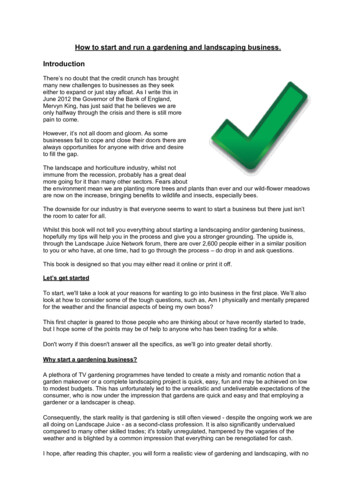
NOTETHE LOW FIRE ADJUSTMENT SHOULDRESULT IN A GAS PRESSURE ON THEBURNER MANIFOLD EQUAL TO 1" WATERCOLUMN FOR NATURAL GAS AND 3" FORPROPANE GAS.2.1.5 MINIMUM INPUT ADJUSTMENT COMBINATION GAS VALVES (VR850 ORVR852)The minimum input on these gas valves is NOTadjustable. The maximum input must be properlyset as outlined in Lighting Instructions. See themanufacturer's instructions on the VR850 orVR852 included in the Boiler Manual for furtherinformation.2.1.6 MINIMUM INPUT ADJUSTMENT - DUALDIAPHRAGM GAS VALVE HIGH/LOW BY-PASSSYSTEMThe minimum input on this control system is NOTadjustable. The maximum input must be properlyset as outlined in Lighting Instructions. Thissystem consists of two V48A (120 volt coil) or twoV88A (24 volts coil) diaphragm gas valves whichare piped in parallel. The minimum input iscontrolled by an orifice plug installed in a couplingin the by-pass piping (low fire valve piping), sizedfor approximately 1" w.c. manifold pressure at lowfire natural gas (2" w.c. if propane gas). When thehigh fire gas valve is not activated, gas flows onlythrough the bypass piping. When the high fire gasvalve is activated, gas will flow though bothvalves achieving full input.2.2 FIRING RATE ADJUSTMENT - GAS METER READINGS2.2.1 CHECKING BURNER INPUTThe burner input rate can be checked by takingreadings from the gas meter. Please notechecking the rate with a meter is the only way tobe sure of input. Manifold readings are only anapproximate value and may vary from unit to unit.In order to obtain accurate data, there must be noother appliances using gas from the same meterwhile the burner input rate is being checked. Thetest hand on the meter should be timed forseveral revolutions. The input rate in cubic feetper hour isTable 2.2A - Pressure Correctioncalculated from this timing. The method isdescribed in Lighting Instructions. If the meter isnot calibrated for gas temperature and pressure,correction factors must be applied to determinecorrect rate in SCFH (standard cubic feet perhour). Consult the National Fuel Gas Code (ANSIZ223.1, NFPA 54) or the local gas utility forfurther information. Refer to Table 2.2A forcorrection factors for the gas pressure at themeter. Refer to Table 2.2B for the gastemperature correction factors.Table 2.2B - Temperature CorrectionGas Pressure at MeterCorrection FactorGas Temp. at MeterCorrection Factor7" w.c.1.01740 F0.92014" w.c.1.03450 F0.90221" w.c.1.05160 F0.8851 psig1.06170 F0.8682 psig1.13680 F0.8525 psig1.34090 F0.836
2.3 SAFETY SHUT-OFF DEVICES (FLAME SUPERVISION)2.3.1 FLAME SUPERVISORY SYSTEMThe boiler is equipped with a flame supervisorysystem, either the Thermocouple type (such as acombination gas valve or a pilotstat) or electronictype (such as the RA890, or RM7895). Thepurpose of this device is to detect the main orpilot flame, depending on the type of device, andcontrol the gas valves accordingly. The devicemust be checked for proper operation. SeeLighting Instructions in the Boiler Manual for thecorrect procedure. The flame supervisory systemmust be tested to assure that it will shut off themain gas valves in case of aflame loss. In addition to the information given inLighting Instructions, operating sequence andtroubleshooting information may be found in themanufacturer's instructions in the Boiler Manual.2.3.2 AUTOMATIC (ELECTRIC) IGNITIONSYSTEMSOn boilers equipped with automatic electricallyignited pilots, follow the procedures described inLighting Instructions and test the controls forproper operation.2.4 LIMIT CIRCUIT CUT-OUT TEST2.4.1 PROTECTIVE DEVICESAll operating and limit controls and low watercutoffs must be tested for proper operation.2.4.2STEAMPRESSUREOPERATINGCONTROLThe steam pressure in the boiler is regulated bythe Boiler Operator. This is a pressure controlwhich senses the steam pressure and turns theboiler on and off accordingly. This control must beoperationally tested. Adjust the pressure settingon the control to a pressure less than the boilerpressure (as shown on the boiler pressuregauge). The control should turn the boiler off.Restore the control setting to normal. The boilershould cycle on.2.4.3 HIGH LIMIT CONTROLAt least one additional pressure control isprovided as the high limit control. It is set at apressure above the operator to act as a back-upshould the operator fail. The high limit controlmust be operationally tested. With the boileroperating, decrease the pressure setting of thelimit control below the current pressure of theboiler. The boiler should cycle off. Restore thehigh limit control setting to normal (pushing restbutton if it is a manual reset type). The boilershould now cycle on.2.4.4 LOW WATER CUT-OFF(S)Most boilers are supplied with a float-operatedprimary low water cut-off (and pump control orwater feeder combination) or electric probe typeauxiliary control. These water level controls areintended to sense (and control) the level of thewater in the boiler. They operate to shut off theboiler if the water level drops below their sensinglevel. The low water cut-off and water levelcontrols must be operationally tested by manuallylowering the boiler water level (by opening theboiler blowdown valve for probe controls, and byopening the control blowdown valve for float typecontrols). The boiler should cycle off when thewater level drops below the control point of thelow water cut-off. When the water level isrestored, the boiler should cycle back on.Depress the manual reset button of deviceswhich require manual reset in order to restore theboiler to operation. Carefully read the enclosedliterature on the low water cut-off controls,particularly installaing, operating and servicing.2.4.5 COMBINATION LOW WATER CUT-OFF &FEEDERThe low water cut-off/feeder supplied with someboiler serves as a low water cut-off (see above)and also causes make-up water to be added tothe boiler should the water level drop below itscontrol point.This type of control must be operationally testedas for low water cut-offs and also to assure thatthe make-up water is introduced as needed.Carefully read the enclosed literature on the Low
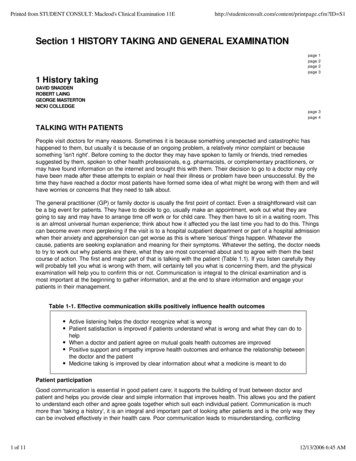
Water Cut-off controls, particularly installing,operating and servicing.2.4.6 OTHER CONTROLSAdditional controls as required for the particularinstallation may also be provided. Refer to theliterature on these devices included in the BoilerManual. All such devices must be operationallytested to assure reliable operation of the boilerand system.2.4.7 BOILER FEED SYSTEMThe boiler feed pump must be operationallytested to assure that it can provide boilerfeedwater at the pressure and in the amountneeded for safe and reliable boiler operation.2.4.8 CHEMICAL FEED SYSTEM & SOFTENERCheck the performance of the boiler watersoftener and chemical treatment system.Chemically test the feedwater to be certain itcomplies with the recommendations of thechemical treatment consultant.2.5 RECOMMENDED DRAFT AND COMBUSTION READINGSATMOSPHERIC GAS-FIRED BOILERSBOILER SERIESDRAFT AT BOILEROUTLET(i.w.c.)CO2 @ HIGHFIREO2 @HIGH FIRECO(ppm)SMOKENO.F-0.01 TO -0.047.5 TO 8.5 %5.0 TO 7.5 % 4000CL-0.02 TO -0.047.5 TO 9.0 %4.8 TO 7.5 % 4000K-0.02 TO -0.068.0 TO 9.5 %4.0 TO 6.7 % 4000FORCED DRAFT GAS FIRED BOILERSBOILER SERIESDRAFT ATBOILEROUTLET (i.w.c.)CO2 @HIGH FIREO2 @HIGH FIRECO(ppm)SMOKENO.D-0.01 TO -0.047.5 TO 9.5 %4.0 TO 7.5 % 4000HED-0.01 TO -0.047.5 TO 9.5 %4.0 TO 7.5 % 4000CL0.0 TO -0.048.5 TO 10.0 %3.2 TO 5.0 % 4000HECL0.0 TO -0.068.5 TO 10.0 %3.2 TO 5.0 % 4000RV & RW 0.50 TO -0.109.0 TO 10.0 %3.2 TO 5.0 % 4000AB 0.25 TO -0.069.0 TO 10.0 %3.2 TO 5.0 % 4000
FORCED DRAFT OIL FIRED BOILERSBOILER SERIESDRAFT ATBOILEROUTLET (i.w.c.)CO2 @HIGH FIREO2 @HIGH FIRECO(ppm)SMOKENO.D-0.01 TO -0.0410.0 TO 12.0 %4.0 TO 7.2 % 4000CL0.0 TO -0.0410.0 TO 12.0 %4.0 TO 7.2 % 4000RV & RW 0.50 TO -0.1011.5 TO 12.5 %3.7 TO 5.0 % 4000AB 0.25 TO -0.0611.5 TO 12.5 %3.7 TO 5.0 % 4000NOTE: THE VALUES FOR CO2 AND O2 ARE SHOWN FOR HIGH FIRE ONLY. THE VALUES FOR LOWFIRE OR MID RANGE WILL GENERALLY BE LOWER, PARTICULARLY FOR ATMOSPHERIC GASFIRED BOILERS. DRAFT SHOULD BE MEASURED APPROXIMATELY 24" FROM TOP OF BOILER,BEFORE ANY DRAFT CONTROL.2.5.1 DRAFT ADJUSTMENT - ATMOSPHERICGAS BOILERSRefer to Section 1.8.6 for the adjustment methodfor barometric dampers. Adjust the damper so asto yield a draft which results in values of CO2 andCO within the allowable limits listed above in theappropriate table.Draft adjustments are generally not required forboilers equipped with draft diverters. The ion readings are required, however, toassure that the boiler operation is both safe andefficient.Draft measurement should preferably be madewith an inclined tube manometer. If a draft gaugeis not available, check to be sure the flue gasesare being carried up the venting system bypassing a lighted taper or match around the edgeof the draft hood relief opening (or barometric). Ifthe venting system is operating correctly, thematch flame will be drawn toward the draft hoodrelief opening. Otherwise the products ofcombustion will tend to push the flame andextinguish it.CAUTIONIF THE PRODUCTS OF COMBUSTION AREBEING EMITTED INTO THE ROOM (VENTINGSYSTEM NOT OPERATING CORRECTLY),THE BOILER MUST NOT BE OPERATEDUNTIL PROPER ADJUSTMENTS OR REPAIRSARE MADE TO ASSURE ADEQUATE DRAFTTHROUGH THE VENTING SYSTEM.2.5.2 DRAFT ADJUSTMENT -FORCED DRAFTBOILERSDraft adjustments are generally not necessary onforced draft boilers. The draft must be measuredas part of the start-up procedure. The measureddraft at the boiler flue should fall within therecommended range specified in the appropriatetable.On some installations the draft may be excessivedue to a high chimney. In these cases, the draftshould be adjusted within the recommendedrange specified in the above appropriate table.This may be done using a barometric damper, arestrictor, or a locking quadrant damper. Suchdevices must be installed and adjusted by aqualified technician.2.5.3COMBUSTIONADJUSTMENTSFORCED DRAFTRefer to the separate burner manual for theprocedures for burner adjustments. The burnermust be adjusted for smooth lightoff. Combustionparameters should be within the range specifiedin the above appropriate table. In no case shouldthe level of CO be allowed to exceed the limitgiven, and the smoke spot reading must also notexceed the value shown.
2.6 OPERATING INSTRUCTIONS2.6.1 FAMILIARIZATION WITH MANUAL(S)The user of the boiler must familiarize himselfwith this manual and the burner manual for forceddraft boilers to be sure he is prepared to operateand maintain the boiler properly.2.7 MAINTENANCE SCHEDULE2.7.1 POSTING SCHEDULEPost a maintenance schedule in accordance withthe recommendations in this manual. A copy of atypical schedule is included in this manual.Section 3The operating instructions should be kept in thepocket in the boiler for F Series boilers, oradjacent to the boiler for all others.READ THE MANUAL BEFORE ATTEMPTING ASTART UP.
CARE AND MAINTENANCESTEAM BOILERS CAUTION:The boiler area should be kept free of combustible materials, gasoline and other flammable liquids.The boiler and venting system must be kept free of obstructions of the air louvers and draft hoodrelief openings.The following procedures must be conducted as outlined to assure safe operation of the boiler.All cover plates, enclosures, and guards must be in place at all times except during maintenanceand servicing.3.1 REQUIRED PRECAUTIONS DURING TEMPORARY USEGENERALA boiler is often utilized in new construction toassist in curing of
The steam pressure in the boiler is regulated by the Boiler Operator. This is a pressure control which senses the steam pressure and turns the boiler on and off accordingly. This control must be operationally tested. Adjust the pressure setting on the control to a pressure less than the boiler pressure (as shown on the boiler pressure gauge). The control should turn the boiler off.