Transcription
CommStat 4 ControllerCommStat 4 Telecom HVAC ControllerThe CommStat 4 is an HVAC controller designedspecifically for controlling two redundant airconditioners, heat pumps and air conditioners withtwo stage compressors in a telecommunicationsshelter or enclosure. In addition to the control ofthe air conditioners or heat pumps, the CommStat 4has seven outputs for remote alarms or notification.The CommStat 4 uses RS-485 communications via aRJ11 communication jack. It is capable of interfacingwith a secondary control board which can interpretMarvair's communication protocol and provide Internetconnectivity. Note: the end user must provide theinterface board and the Graphical User Interface (GUI)software to gain access via the Internet.The CommStat 4 is factory programmed withstandard industry set points, but can be configured onsite. Settings are retained indefinitely in the event of apower loss.CONTROL UP TO SIX AIR CONDITIONERS OR HEAT PUMPS IN A SHELTERThe CommStat 4 has the capability to be daisy chained with up to two additionalCommStat 4 controllers for controlling up to six air conditioners or heat pumps in ashelter. When two or three CommStat 4 controllers are daisy chained together, one of thecontrollers is the Master and controls all connected CommStat 4 controllers. Any settingsto the Master unit immediately take effect on the Slave units. The interface for the daisychain is an RJ11 connector.EASE OF CONTROL AND CONFIGURATIONA large, backlit LCD display shows the status of the system and provides a convenientuser interface. Status LEDs indicate Heat, Cool, Power and the Lead Unit. When a fault isdetected, an alarm LED flashes and the LCD screen displays the fault. If multiple faults aredetected, the display will scroll the faults across the screen.The CommStat 4 is easily configured with four buttons. A Comfort button changes thetemperature in the shelter for 90 minutes. After 90 minutes, the temperature revertsback to the programmed set points. A lead swap button alternates the lead and lag unit,allowing service techs to quickly check the operation of each unit.For security, the keypad can be locked out to prevent unwanted changes to the setpoints. English, Spanish or French is selectable as the language shown on the display. For C is selectable.RoHS COMPLIANTThe CommStat 4 controller contains no hazardous materials and is RoHS compliant.P/N 01675 rev. 3CommStat 4 PD, 11/2010
Specification/FeaturesThermostat Cooling Set Point: 65 F through 95 F (18 C through35 C) in 1 increments. Heating Set Point: 50 F through 80 F (10 Cthrough 27 C) in 1 increments.ously for 4 seconds. Alarms can be reset providedthere is no longer an input from the smoke detector.All alarms are functional when 24 VAC is applied tothe board. If 24 VAC is not present, no alarms will bedisplayed unless DC power is present. If DC power issupplied to the board, the display is operational.Differential ON-OFF Differential of Stage One: 2 F through 5 F High (Line) Voltage - activated if line voltage is not(1 through 3 C) in 1 increments.present. The CommStat 4 requires a line voltage ON-OFF Differential of Stage Two: 2 F through 5 Fof 230VAC input from each air conditioner or heat(1 through 3 C) in 1 increments. The 2nd stagepump to monitor for the presence of line voltage.differential is referenced to the 1st stage differentialIf line voltage is not present, the High Voltage Lossand the outputs will stage off as each stage’salarm relay is energized.differential is satisfied. Low (Control) Voltage – activated if control voltage Changeover Differential between cooling andis not present.heating: Minimum of 4 F (2 C). Lockout – activated if any air conditioner or heat 3rd stage heating Differential: 0 F through 7 F (0 Cpump is off due to either high or low refrigerantthrough 4 C) in 1 incrementspressure lockout. If all the air conditioners or heatControl Voltagepumps are locked out, the Mixed Air Relay (MAR) The CommStat 4 is powered by a nominal 24will be activated on each of the air conditioners orVAC and has a backup power supply of 24VDC orheat pumps. This air conditioner or heat pump will48VDC applied constantly. Should AC power be lost,go into the Ventilation mode, provided there is athe display, user interface and the alarm outputscall for cooling. If desired, the lockout alarm canremain functional. System outputs (Y, G, W, O andbe disabled by the user in the Configuration Set-up.the Mixed Air Relay) will not be functional when Low Building Temperature Alarm – Activated if the24 VAC is not present. If the control voltage istemperature in the building drops to the selectednot present, the Low Voltage Loss alarm relay istemperature. If the low building temperatureenergized.alarm is activated, the LCD displays, “Low BuildingTemperature”.Operating Range: -40 F through 150 F (-40 C First Stage High Building Temperature Warning – Ifthrough 66 C)the set point temperature is reached, the displayMinimum Voltage: 18 VACwill show, “First Stage High Building Temperature”Maximum Voltage: 30 VACon the LCD display. Second Stage High Building Temperature AlarmEase of Installation- If the set point temperature is reached, the Wiring connection insensitive to phasing of thedisplay will show, “Second Stage High Buildingunits.Temperature” on the LCD display and all outputs Easy terminal connections for thermostat wire.are turned off with the exception of the Mixed Remote temperature sensors insure accurateAir Relay (MAR) and the Air Mover Relay (AMR).temperature readings in the shelter.If the air conditioner(s) or heat pump(s) on the Easy attachment to the wall.shelter have economizer(s) and DC inverter(s), theLead/Lag Operationeconomizer(s) will open, and the indoor blower(s) User selectable changeover from ½ to 7 days in ½will be energized (Emergency Ventilation Mode).day increments. If the lead unit loses power, the lag Smoke Alarm – the contacts will be energizedunit automatically becomes the lead unit with allwhen the smoke detector inputs receive a signalthe set points of the lead unit. A lead swap buttonfrom an external detector. All air conditioners oralternates the lead and lag unit, allowing serviceheat pumps are immediately shut down. A physicaltechs to easily check the operation of each unit.reset is required to clear the alarm in the manualmode. If auto reset has been selected, the alarmwill reset after the user specified time (3-10minutes). AUX1and AUX2 – Two auxiliary dry contact outputsAlarmsthatcanbe energized based upon AUX1 and AUX2Dry contacts can be used for remote alarm or notiinputs.fication. Relays can be wired Normally Open (NO)or Normally Closed (NC). Most alarm relays can bereset by turning the CommStat 4 OFF and then ONOR the UP and DOWN buttons are held simultaneCommStat 4 PD, 11/2010 rev. 32
CommStat 4 Lead/Lag Controller Inputs1. Input PowerThe R and C terminals are the input power terminals for each respective air conditioner or heat pump.2. Modem ConnectionThe modem connection is used for remote communication and remote programming of the CommStat 4.It has the capability of providing shelter temperatures, mode of operation, as well as remote diagnosis. Allconfiguration settings can be viewed and changed remotely.3. Control Voltage (24 VAC)The CommStat 4 is powered by 24 VAC and has a back up power supply of 24 or 48 VDC appliedconstantly. Should AC power be lost, the display, user interface and alarm outputs of the CommStat 4will still be functional. However, the system outputs of the CommStat 4 (Y, G, W, O, and MAR) will not befunctional when 24 VAC is not present.4. Line VoltageThe CommStat 4 uses line voltage of 230VAC input from each unit air conditioner to monitor for thepresence of line voltage. If a line voltage loss is not present, the CommStat 4 will energize the HighVoltage Loss Alarm relay.5. Temperature SensorsThe CommStat 4 uses remote temperature sensor(s) to measure the temperature in the shelter anddetermine when the system is calling for heating or cooling. Up to three sensors can be connected to eachCommStat 4. There are two options for the sensors. If No (the default setting) is selected and multiplesensors are being used, the temperatures will be averaged. If Yes is selected and multiple sensors arebeing used, the sensor with the highest reading will be used for cooling operation and the one with thelowest reading will be used for heating. When multiple sensors are being used and there is a temperaturedifferential greater than or equal to 5 F (4 C) between the sensors, the CommStat 4 lead/lag controllerwill energize the indoor blowers (G) on all connected units.Screen #20 in the Configuration Mode allows the user to determine how the temperature sensors will beconfigured.6. Smoke DetectorThe smoke detector input terminals determine when there is a signal from an external smoke detector.They can be configured for either a Normally Open (N.O.) or Normally Closed (N.C.) smoke signal inConfiguration screen # 18. During a smoke fault condition, all AC units will be turned off.The smoke alarm relay reset has two selections -Manual (default) and Auto. If Manual is selected, aphysical reset of the fault is required by holding the Up and Down buttons for 4 seconds. Cycling powerwill not reset a smoke fault if Manual is selected.If Auto is selected the alarm will reset after an adjustable time delay of 3-10 minutes.Screen #17 in the Configuration Mode allows the user to determine how the smoke alarm relay reset willbe configured.7. Hydrogen DetectorThe hydrogen detector input terminals will determine when there is a 24 VAC signal from an externalhydrogen detector. The CommStat 4 will switch the lead unit to Emergency Ventilation mode (ComPac IIair conditioners or Classic heat pumps with economizers only) when high hydrogen levels are detected. Itwill switch back to normal air conditioning mode once the hydrogen levels are acceptable and the 24 VACsignal is removed from the hydrogen detector input terminals.8. Generator RelayThe generator input will monitor for a 24 VAC signal which will be used to determine when the CommStat4 is operating on generator power. When 24 VAC is recognized at the generator relay input, the CommStat4 controller will only operate the units selected by the user in screen # 16 of the Configuration Menu. Theoptions are:a. to run only the lead unit (default),b. the lead unit and one lag unit,c. the lead unit and two lag units, ord. the lead unit and three lag units.9. Economizer Mode Status MonitoringThe 2 terminal is monitored for a 24 VAC signal. When the 2 terminal has 24 VAC present, mechanicalcooling will be energized and the cooling LED will be lit. When 24 VAC is not present at the 2 terminal,the unit will be in economizer mode and this status will be annunciated on the LCD display. Economizermode is defined as a call for cooling (24VAC output at Y and O) with no 24VAC signal at the 2 terminal.Mechanical cooling is defined as a call for cooling (24VAC output at Y and O) while there is a 24VAC signalat the 2 terminal.3CommStat 4 PD, 11/2010 rev. 3
CommStat 4 Lead/Lag Controller Inputs (cont'd)10. Lockout Relay (LOR)The CommStat 4 has a lockout relay input (LOR) and will provide a Normally Open (NO) or NormallyClosed (NC) output in accordance to this input. This feature is enabled in the Configuration Mode, screen#10 by either selection On (default) or Off. If On is selected, the control will turn the output off, energizethe lockout relay output (NO or NC), and annunciate which unit is locked out on the LCD display. If all theunits are locked out, the mixed air relay will be activated on each unit to provide emergency ventilation,provided there is a call for cooling.Cycling power will not reset the Lockout fault. A physical reset of the fault will be required by pressing theUp and Down buttons for 4 seconds.11. AUX1-IN/AUX2The CommStat 4 has the option for two, dry contact, auxiliary outputs that will energize based on theAUX1 and AUX2 inputs. Each AUX input can be configured to look for a normally open (NO) or normallyclosed (NC) signal in Configuration Mode, screens # 21 and # 22. Each screen will allow the user theoption of NO, NC, or OFF to disable the feature.AUX1 and AUX2 are independent from the operation of the board and the air conditioners or heat pumps.CommStat 4 Lead/Lag Controller Outputs1. Y or 1The Y or 1 output energizes the compressor when the economizer is not selected. Upon a call for cooling,the Y (1) and O terminals are energized. On a call for 1st stage heating, the Y(1) output will be energized.There is a minimum compressor time off delay of 3 minutes for the lead unit and 4 minutes for the lagunit. A minimum compressor run time is preset at three minutes by the controller.2. G or 3The G or 3 output terminal energizes the indoor fan during either heating or cooling.3. W or 4The W or 4 output terminal energizes the electric heat.4. O (Heat Pumps) or Y2 (Air Conditioners with 2 Stage Compressors)The O output terminal energizes the reversing valve on heat pumps. The valve is energized on a call forcooling. If staged air conditioners are selected in Configuration screen #25, the O output becomes thesecond stage cooling output, Y2.5. Lockout AlarmWhen enabled in screen #10 of the Configuration Menu, the CommStat 4 monitors the Lockout Relay(LOR) input for a contact closure. If there is a contact closure between the LOR terminals, the controlwill turn off all outputs, energize the NO or NC contacts, and display which unit is locked out on the LCDdisplay. The default setting in the configuration is “On”. If all of the connected units are locked out,the Mixed Air Relay (MAR) will be activated on each of the connected units and the units will go intoEmergency Ventilation mode. Cycling power will reset the Lockout Alarm.6. Low (Control) Voltage Loss AlarmThe low voltage loss alarm relay provides a dry contact closure if control voltage is not present.7. High (Line) Voltage Loss AlarmThe high voltage loss alarm relay will provide a dry contact closure if line voltage is not present.8. Low Building Temperature AlarmThe Low Building Temperature Alarm has an adjustable temperature range of 30 F thru 65 F (-1 C thru19 C) that may be adjusted in screen #8 of the configuration menu. If the temperature drops to thissetting, all outputs will be turned off and the LCD display will annunciate Low Building Temperature. Thereis a 2 F (1 C) differential for this alarm to reset.9. First Stage High Building Temperature WarningThe set point temperature is adjustable from 70 F thru 140 F (21 C thru 60 C). If this set point isreached, the control will display a First Stage High Building Temperature warning on the LCD display. Thedefault setting for this is 85 F (29 C). There is a 2 F (1 C) differential for this alarm to reset. The firststage high temperature warning temperature is adjustable in screen #6 of the Configuration Menu.10. Second Stage High Building Temperature AlarmThis set point is adjustable from 75 F thru 145 F (24 C thru 63 C). If this set point is reached, all outputsare turned off with the exception of the Mixed Air Relay (MAR) and Air Mover Relay (AMR), and the controlwill display a Second Stage High Building Temperature alarm on the LCD display. The economizers (if airconditioners or heat pumps with economizers are installed) will run in the emergency mode and the indoorblower will be energized with a DC inverter (if an inverter is present). There is a 2 F (1 C) differentialCommStat 4 PD, 11/2010 rev. 34
CommStat 4 Lead/Lag Controller Outputs (cont'd)for this alarm to reset. The temperature for the second stage high temperature alarm can be selected inscreen #7 of the Configuration Menu.11. Smoke alarmThe smoke alarm is energized when the smoke detector inputs sense a smoke fault condition. All outputsare off and the smoke alarm relay is energized during a smoke fault. This is a dry contact output that canbe configured for NO or NC (default) operation in setting #18 of the configuration menu.The smoke alarm has two selections -Manual (default) and Auto. If Manual is selected, a physical resetof the fault is required by holding the Up and Down buttons for 4 seconds. Cycling power will not reset asmoke fault if Manual is selected.If Auto is selected the alarm will reset after an adjustable time delay of 3-10 minutes. Screen #17 in theConfiguration Mode allows the user to determine how the smoke alarm relay reset will be configured.12. Mixed Air Relay (MAR)The MAR output is be energized by the CommStat 4 when the second stage high temperature alarm hasbeen activated. This is referred to as the Emergency Ventilation Mode.13. DC Air Mover Relay (AMR)The DC Air Mover Relay has a dry contact output and is energized in the Emergency Ventilation Mode.14. AUX1 and AUX2The CommStat 4 has the option for two, dry contact, auxiliary outputs that are energized based on theAUX1 and AUX2 inputs. Each AUX input can be configured to look for a normally open (NO) or normallyclosed (NC) signal in configuration screens #21 and #22. Each configuration screen allows the user theoption of NO, NC, or OFF (default) to disable the feature. The AUX1 and AUX2 outputs provide a NO, NC,and COM terminal.Important Safety PrecautionsWARNINGALWAYS TURN OFF POWER AT THE MAIN POWER SUPPLY BEFORE INSTALLING, CLEANING, ORREMOVING THERMOSTAT. This thermostat is for 24 VAC applications only; do not use on voltages over 30 VAC Do not short across terminals of system control to test operation; this will damage your thermostat andvoid your warranty All wiring must conform to local and national electrical and building codes Use this thermostat only as described in this manual5CommStat 4 PD, 11/2010 rev. 3
To Install CommStat 4 Telecom ControllerWARNINGELECTRICAL SHOCK HAZARDTURN OFF POWER AT THE MAIN SERVICE PANEL BY REMOVING THE FUSE OR SWITCHING THEAPPROPRIATE CIRCUIT BREAKER TO THE OFF POSITION BEFORE REMOVING THE EXISTINGTHERMOSTAT.IMPORTANTCommStat 4 installation must conform to local and national building and electrical codes andordinances.Note: Mount the CommStat 4 about five feet above the floor. Do not mount the CommStat 4 on an outsidewall, in direct sunlight, behind a door, or in an area affected by a vent or duct.1.Turn off power to the heating and cooling system by removing the fuse or switching off the appropriatecircuit breaker.2. Put controller against the wall where you plan to mount it (Be sure wires will feed through the wireopening in the base of the CommStat 4).3. Mark the placement of the mounting holes.4. Using a drill bit, drill holes in the places you have marked for mounting.5. Align CommStat 4 with mounting holes and feed the control wires through wire opening.6. Use screws to mount CommStat 4 to wall.7. Insert stripped, labeled wires in matching wire terminals. See Wiring Diagrams. CAUTION!: Be sureexposed portion of wires do not touch other wires.8. Gently tug wire to be sure of proper connection. Double check that each wire is connected to the properterminal.9. Seal hole for wires behind CommStat 4 with non-flammable insulation or putty.10. Replace cover on CommStat 4.11. Turn on power to the system at the main service panel.12. Test CommStat 4 operation as described in “Testing the CommStat 4”.Remote Sensor Installation1.2.3.4.Remove cover from remote sensor(s) housing.Select an appropriate location for mounting the remote sensor(s).Mount remote sensor(s) unit using hardware provided.Install two wires between remote sensor(s) and CommStat 4 (use shielded cable that is adequatelygrounded). Wire 1 should run between the S1 terminal on the CommStat 4 and the S1 terminal on the remotesensor Wire 2 should run between the S2 terminal on the CommStat 4 and the S2 terminal on the remotesensorOptional Accessories Remote Sensor (P/N 50189) Expansion Cable (P/N 80515) To be used when multiple CommStat 4 controllers are installed in aMaster/Slave configuration.CommStat 4 PD, 11/2010 rev. 36
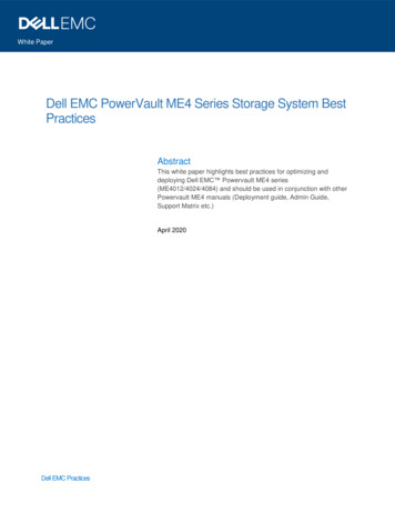
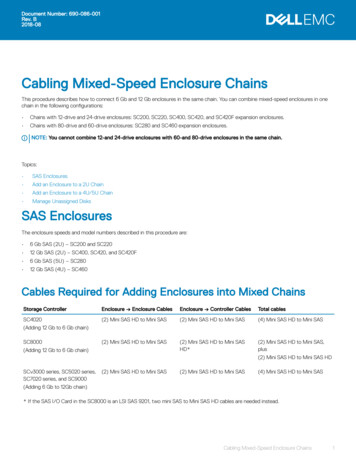
Thermostat and Line Voltage Connections SchematicDimensional Data7CommStat 4 PD, 11/2010 rev. 3
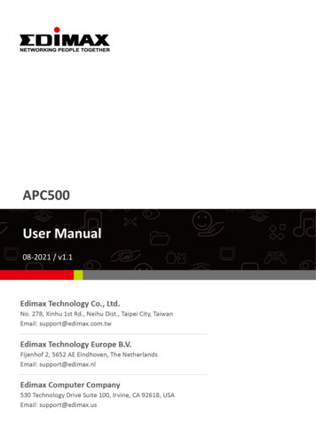
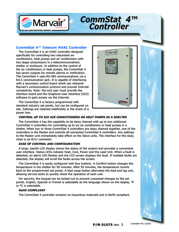
Alarm Connections SchematicCommStat 4 PD, 11/2010 rev. 38
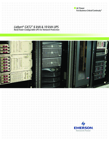
Operating the CommStat 4 Telecom ControllerThe CommStat 4 is controlled with buttons as described below.On/Off ButtonThe On/Off button turns the CommStat 4 on or off. If the system is running in the cooling or heatingcycle when this button is pressed, all outputs will turn off. It also clears unit lockouts and reset alarms aslong as all faults have cleared. To clear alarms and reset alarms, push and hold the On/Off button for 5seconds.Comfort ButtonThe Comfort button enables comfort mode operation. Pushing the Comfort button twice while in normaloperating mode allows the user access to adjust the cooling and heating temperature settings for Comfortmode. The CommStat 4 will revert to normal operation after 90 minutes in the Comfort mode. It can alsobe removed from Comfort mode manually by pressing the Comfort button once.The Comfort mode allows the service tech to be comfortable while working in the shelter. By revertingback to the desired set points after 90 minutes, energy costs can be minimized if the tech forgets to resetthe temperature.Up ButtonThe Up button is only functional when in the Configuration mode or when used in conjunction with theDown or Mode buttons in the normal operating mode. It is primarily used to set values while configuringthe controller. Simultaneously pressing the Up and Down buttons for 4 seconds, while in normaloperation, will reset the alarm relays, and status LEDs with the exception of the lockout alarm whichrequires the power to be cycled at the AC units. Simultaneously pressing the Up and Mode buttons for 4seconds, while in normal operation, changes all settings to the default values.Down ButtonThe Down button is only functional when in the Configuration mode or when used in conjunction withthe Up button in the normal operating mode. It is primarily used to set values while in the configurationmode. Simultaneously pressing the Up and Down buttons for 4 seconds, while in normal operation, willreset the alarm relays, and status LEDs with the exception of the lockout alarm which requires the powerto be cycled at the AC units.Mode ButtonThe Mode button is only functional in normal operating mode. Pushing the Mode button for 4 secondsin the normal operating mode will activate the CommStat 4 Configuration mode. The settings can beadjusted using the Up or Down buttons. The Mode button is mashed to accept the values and advanceto the next setting. Pressing the Mode and Up buttons simultaneously for 4 seconds, while in normaloperation, will change all settings to the default values.Fault History StorageThe CommStat 4 has a fault history storage feature that stores the last 10 faults that were registered.The fault history is accessed by holding the Comfort button for 5 seconds. Scroll through the fault historyby pressing the Up and Down buttons. To return to the normal operating screen and keep the faultsstored in memory, press the Comfort button once. To clear the fault memory, hold the Comfort buttonfor 5 seconds while on the fault viewing screen. This will clear the fault history and return to the normaloperating screen.Lead Swap ButtonHold down to alternate the Lead and Lag units. Functional only when in the Normal or Comfort operatingmode and both units are functional.Lag Unit Economizer OperationWhen the lead unit is in the Economizer mode, the lag or second stage unit, will only operate in themechanical cooling mode. The CommStat 4 will not allow the lag unit to operate in the economizer mode. TheCommStat 4 provides a 24 vac signal to terminal 2 on the lag unit through an internal relay to bypass theenthalpy controller and operate in the mechanical cooling mode until second stage cooling set point is reachedCommStat 4 Lead/Lag Controller Configuration ScreensTo enter the Configuration Mode:1. Make sure that the CommStat 4 is in the normal operating mode.2. Push the Mode button for 4 seconds.3. Press the Up and Down buttons to change the set points.4. Press the Mode button to accept the settings and advance to the next screen.To change all settings to the default values, press the Mode and Up buttons simultaneously for 4 secondswhile in normal operation.To exit configuration mode, do not touch any of the buttons for 5 seconds.9CommStat 4 PD, 11/2010 rev. 3
ScreenNumberDescriptionDefault1Keypad LockoutSelect OFF to disable lockout or a 3 digit number to enable lockout.OFF2 F or C F3Lead/Lag air conditioner changeover. 0.5 to 7 days in ½ day increments7 days4Cooling set point. 65 F thru 95 F (18 C thru 35 C) in 1 increments.75 F (24 C)5Heat set point. 50 F thru 80 F (10 C thru 27 C) in 1 increments68 F (20 C)6First stage high temperature warning set point. 70 F thru 140 F (21 Cthru 60 C) in 1 increments85 F (29 C)7Second stage high temperature alarm set point. 75 F thru 145 F (24 Cthru 63 C) in 1 increments.90 F (32 C)8Low building temperature alarm set point. 32 F thru 65 F (0 C thru18 C) in 1 increments55 F (13 C)9Continuous indoor blower on all air conditioners Select ON or OFFOFF10Alarms0 No alarm output. Screen does not display High voltage fail.1 No alarm output. High voltage input required.2 Alarm output. Screen does not display High voltage fail.3 Alarm output. High voltage input required.311Anti-short cycle timer. 0 no delay or 3-10 minutes in 1 minuteincrements012Differential for 3rd stage htg. 0 F thru 7 F (0 C thru 4 C) in 1 increments2 F (1 C)131st stage temperature differential 2 F thru 5 F (1 C thru 3 C) in 1 increments. This setting only affects the turning on of the system. Theturn off differential is fixed at 1 F/C.3 F (2 C)142nd stage temperature differential 2 F thru 5 F (1 C thru 3 C) in 1 increments. This differential is in reference to the 1st stage differentialand the outputs are staged off each stage’s differential is satisfied.3 F (2 C)15Cooling blower off time delay. 0-90 seconds in 1 second increments90 seconds16Operational units on generator power1 Lead unit only2 Lead unit & one lag unit3 Lead unit and two lag units4 Lead unit and three lag units117Smoke alarm relay resetAutomatic after 3-10 minutes or Manual.Manual18Smoke detector contacts Normally Open or Normally Closed. Whenconfigured for N.O., an open circuit between the smoke terminals willbe considered a smoke fault. When configured for N.C., a closed circuitbetween the smoke input terminals will be considered a smoke fault.NormallyClosed19Economizer ConfigurationYes ComPac II unit with economizerNo ComPac I unit without economizerIf "No" is selected, the emergency ventilation function does notoperate.No20Remote temperature Sensor(s). If No (the default) is selected and multiplesensors are being used, the temperatures will be averaged. If multiplesensors are being used and Yes is selected, the sensor with the highesttemperature reading will be used to control the units when in the coolingmode. In heating, the sensor with the lowest reading will be used to controlthe units.No21AUX 1 dry contact output. Selection are:NO Output will be energized when there is no contact closure between theAUX1-IN terminals.NC Output will be energized when there is contact closure between theAUX1-IN terminalsOFF DisabledOffCommStat 4 PD, 11/2010 rev. 310(Continued on following page.)
ScreenNumberDescriptionDefault22AUX 2 dry contact output. Selection are:NO Output will be energized when there is no contact closure between theAUX2-IN terminals.NC Output will be energized when there is contact closure between theAUX2-IN terminalsOFF DisabledOff23Excessive compressor operation. Select between 5-10 cycles per twohour period or “No” to disable. When set between 5-10 cycles and thecompressor cycles more than the set point, the first stage differential willincrease by 2 F (1 C).No24Language Select either English, French or SpanishEnglish25Select either 1-stage air conditioner, 2-stage air conditioner or heat pump.1 1-stage air conditioner2 2-stage air conditionerNo Heat pumpIf the CommStat 4 Controller is configured for 2-stage air conditioner, theCommStat 4 Controller only functions as a master, stand alone unit. It cannot be used as a slave unit.126Master/Slave setting. When connected to another CommStat 4, the userselects whether this unit is the Master (Yes) or Slave (No).Yes27Differential setting between the 3rd and 4th stages when the CommStat 4is being used in a Master/Slave application. This screen only appears if No isselected in screen #25.3 F (2 C)Testing the CommStat 4 Thermostat ControllerCheck-Out of Cooling CycleDue the wide range of configurations, the following instructions are limited to checking the operation ofthe cooling and heating modes. If alarm or fault conditions are displayed, recheck all field wiring and theconfiguration screens.Important: Be sure that the crankcase heater (if used) has been energized for at least 24 hours beforestarting the unit(s). Double-check all electrical connections before applying power. ComPac air conditionerswith scroll compressors running on 3Ø power must be checked for proper rotation during the initial start-up.Please refer to ComPac Installation & Operation manual for determining if the 3Ø compressors are rotatingcorrectly. Incorrect rotation can damage the compressor and is not covered by the warrantyProcedure:1. In the Configuration screen No. 4, set the cooling set point temperature to a point higher than theambient temperature. In the Configuration screen No. 5, set the heating set point temperature to atemperature that is lower than the ambient.2. Set the time delay in the ComPac I or ComPac II A/C control box to three minutes. On ComPac II airconditioners with the economizer, check the changeover setting of the H205A or dry bulb sensor and resetit if needed. (See ComPac air conditioner Installation & Opera
4 controller will only operate the units selected by the user in screen # 16 of the Configuration Menu. The options are: a. to run only the lead unit (default), b. the lead unit and one lag unit, c. the lead unit and two lag units, or d. the lead unit and three lag units. 9. Economizer Mode Status Monitoring