Transcription
RSL-OM-1006 OPERATION & MAINTENANCE MANUALSQUARE DRIVE SETHEX WRENCH SETSALES, PARTS, REPAIR, CALLIBRATION, SERVICE and RENTAL:Western hemisphere: 2440 E. Pasadena Freeway, Pasadena, TX 77506, tel. 713-860-4200, toll free in USA: 1-800-895-3849Eastern hemisphere: Bentley Road South, Darlaston, West Midlands, WS10 8LQ England, Phone: 0121 50 50 600Optional - REPAIR and CALLIBRATION: 2010 Clermont Street, Antigo, WI 54409, tel: 715-627-5519, fax: 715-627-5544, toll free in USA: 1-800-569-6807WEB SITE: http:/www.hydratight.com Hydratight, 2006
TABLE OF CONTENTSPAGESAFETY FIRST ------------------------- 3SECTION 1 – GENERALBRIEF DESCRIPTION ----------------------------------------- 4PREPARATION FOR OPERATION ------------------------ 4SECTION 2 – GENERAL OPERATION INSTRUCTIONSGENERAL ------ 5TIGHTENING --------------------------------------- ------------ 6ALTERNATE – STUD ELONGATION METHOD -------- 7LOOSENING ---------------------------------------- ------------ 7STUD/NUT SIZE CROSS REFERENCE ------------ ------ 10PRESSURE/TORQUE CONVERSION CHART ---------- 11SECTION 3 – RSL POWER HEAD WITH HEX WRENCH HEAD OPERATING INSTRUCTIONSGENERAL ----- 12ASSEMBLY OF COMPONENTS --------------------------- 13SECTION 4 – RSL POWER HEAD WITH SQUARE DRIVE WRENCH HEAD OPERATING INSTRUCTIONSGENERAL ----- 15ASSEMBLY OF COMPONENTS --------------------------- 16OPERATING RSL TOOL WITH THE SQUARE DRIVE WRENCH HEAD -------------------------- 16SET–UP AND USE -------------------------------------------- 17SECTION 5 – PREVENTIVE MAINTENANCERSL POWER HEAD ------------------------------------------- 18RSL HEX AND SQUARE DRIVE WRENCH HEADS -- 20SECTION 6 – TROUBLESHOOTING --------------------------------------------- 20SECTION 7 – PARTSRSL POWER HEAD ------------------------------------------- 22RSL HEX WRENCH HEAD PARTS LIST ---------------- 24RSL SQUARE DRIVE WRENCH HEAD PARTS LIST -------------------------------------------------- 25RSL REACTION ARM ASSEMBLY PARTS LIST ------ 26SEAL KITS, PARTS LIST AND PLACEMENT GUIDE -27RSL TOOL DESCRIPTIONS -------------------------------- 28SECTION 8 – TENSION AND ELONGATIONTENSION ------ 29TORQUE ---------------------------------------------- ---------- 29ELONGATION ------------------------------------------------- 29NOTES ------------------------------ 30SAFETY TAG ------------------------------------------------ ---------------------- 31WARRANTY -- ------------------- 32This tool, when used in conjunction with the specified console and hoses, conforms with the requirementsfor CE Marking. Contact Hydratight for a list of approved components.2
SAFETY FIRSTRSL power tools enable the user to more easily accomplish bolting tasks with increased force, accuracy, and efficiency. It is due tothe powered nature of the tools, with large forces generated from high pressure fluid/air and electricity applied to a variety ofapplications, that adherence to strict safety issues through the proper design and documented use of RSL tools. However, the usermust accept the primary responsibility of safety when using RSL tools by reading, understanding, and complying with all operatinginstructions prior to and during operation. In a commitment to facilitate user understanding of all operating instructions,HYDRATIGHT offers (upon request) free videotapes and on-site training by a local representative. This manual and additionalsafety related services are designed to assist in the proper training for use and care of RSL tools and play a major role in preventingaccidents and increasing safety.The following safety related operating instructions are documented in the manual and on a Safety Tag which should always beattached to the hydraulic pump when in use:Operator must read and understand all operating instructions prior to operations! In addition to this Manual,HYDRATIGHT offers (per request) videotapes and/or training on site by local representative.One-person operation recommended. Only one trained & competent person should control the operation of the tool.When two-person operation cannot be avoided a risk assessment must be undertaken that fully address the specificapplication, communication, & co-ordination of the tool operation between the two users, the person HOLDING thewrench should control operations. (Note: The person in control does not necessarily have the control pendant in hispossession, but will give the commands to energize the console.)Do not use electric pump in explosive or wet environment! If electric pump is used, assure that grounding, powersupply, and extension cord meet electrical code. Be aware of electrical hazards.Keep hands and fingers clear from pinch points! Pinch points are present around reaction area and in tight spaces.Set reaction properly! Improper reaction set-up and/or incorrect socket size will cause a concentration of stress thatcan make the tool, socket, or nut vulnerable to fracture. The common cause of socket breakage is cocking, a conditionwhen socket fits over the bolt at an angle. Read this manual for examples of “how to” and “how not to” react, with andwithout Reaction Arm.High hydraulic pressure hazards, 10,000 psi (690 bar)! Use proper tools, hoses, fittings and protective equipment. Keep clear of leaking hydraulic fluid. Never exceed the maximum working pressure. Marking on the Wrench Head indicates maximum workingpressure requirements.Wear safety glasses! Eye protection is necessary when working with or near the pressurized hydraulic system.Do not expose hoses to damaging conditions! Hose damage may result from mechanical, thermal, or chemical abuseand may release hydraulic fluid under pressure and cause injury.Disconnect all power supply before performing any maintenance!Maintain equipment in good working condition! Inspect for cracks, wear, and lubricate moving parts withSWEENEY 503 lubricant. Remove damaged equipment from service.Do not modify or subject any equipment or accessories to impact! Contact HYDRATIGHT for special toolapplications or modifications. Unauthorized modification(s) may cause injury.To avoid possibility of falling objects in elevated areas, tool must be tied off to application area and reaction arm firmly attached to tool!Reaction arm must be firmly attached with locking devise provided as part of arm (Dialock, ) and can be further retained by safety cable.Contact Hydratight for Bulletin 116, which shows how to tie reaction arm to tool with cable.3
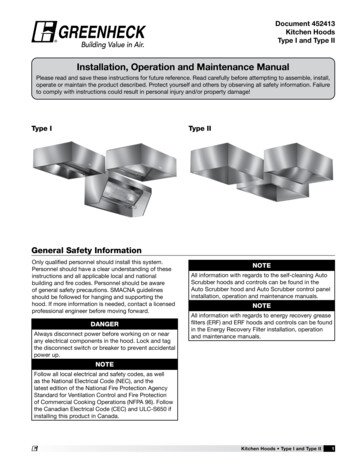
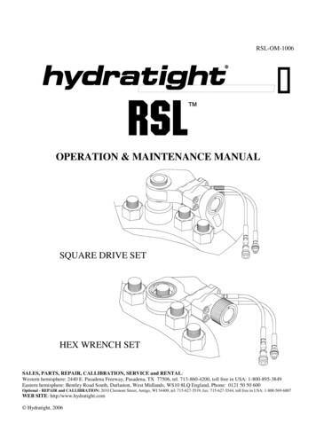
SECTION 1GENERALFIGURE 1-1RSL POWER HEADBRIEF DESCRIPTIONRatcheting Slim Line (RSL) Tool is operated with 10000 psi (690bar)* hydraulic pressure and is used to apply a specific tension to studs,bolts and cap screws by applying the proper torque value for a specificbolting material, size and type of lubrication. The Tool is also used toremove the tension when loosening is necessary.Caution! Do not modify any equipment oraccessories. Contact HYDRATIGHT forspecial application(s) or modification(s).Unauthorized modification(s) may causeinjury and damage, and will invalidate thewarranty.The Tool is powered by a Console (hydraulic pump). The desiredtension is achieved by precisely controlling the hydraulic fluid pressureproduced by the Console and controlling the frictional force exertedbetween the studs and nuts. The hydraulic fluid pressure produced bythe Consoles is accurate to 1%. The friction force is controlled byapplying a lubricant with a known coefficient of friction to the threadsand mating surfaces.PREPARATION FOR OPERATIONTools are inspected and tested at the HYDRATIGHT factory prior toshipment and should be ready for immediate use. However inspectionof the Tool for damage and verification that all loose parts areincluded, is recommended.RSL Tool is offered in Seven standard models:(Example of RSL tool is shown in figure 1-1)* HYDRATIGHT offers full torque and limited torque RSL WrenchHeads –see marking on the housing.RSL2 with a maximum torque output of 1408 ft-lb. (1909 N-m)RSL4 with a maximum torque output of 3080 ft-lb. (4176 N-m)RSL6 with a maximum torque output of 5303 ft-lb. (7190 N-m)RSL8 with a maximum torque output of 7862 ft-lb. (10660 N-m)RSL14 with a maximum torque output of 11154 ft-lb. (15123 N-m)RSL20 with a maximum torque output of 18843 ft-lb. (25514 N-m)RSL30 with a maximum torque output of 28002 ft-lb. (37966 N-m)4
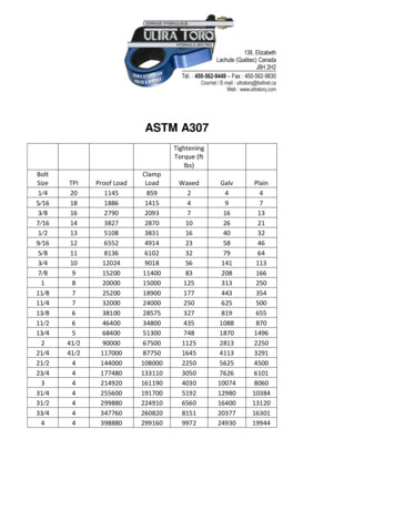
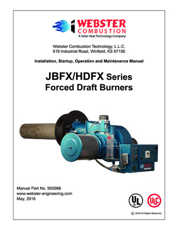
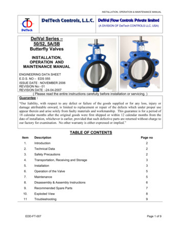
SECTION 2GENERAL OPERATING INSTRUCTIONSSTEP 3 Select the Console, which best meets the requirements of theGENERALapplication.The steps to be followed in selecting the correct Tool and Console for theApplication and setting-up- the Tool are as follows:STEP 4. Connect the air or electrical power source, as applicable,to the Console.STEP 1 Determine the torque value1.STEP 5. Connect the Twin Hoses to the Console. Each end of thehose will have one male and one female quick connect fitting. The Consolewill have like male/female quick connect fittings. Unscrew the locking collaron the female QD. Slide the outside slide ring back and snap the male andfemale together release the slide ring. Screw the locking collar back againstthe side ring.Slide RingThe torque value to be used for applying tension should be the valuespecified by the equipment manufacturer whenever it is available.For convenience, chart of torque values for common sizes of ASTMA193 Grades B7 and B16 studs and lubricants are shown in Figures 21 and 2-2. The torque values in the charts are based upon thefollowing:Locking CollarInch size studs are per ASTM A193, Grade B7 or B16, as applicable,with 10 UNC thread form on 3/4 inch studs, 9 UNC on 7/8 inch studs,8 UNC on 1 inch studs, and 8 UN on 1 1/8 inch and larger studs. Inchsize nuts are heavy hex per ASTM A194, Grade 2H. Metric size studmaterials and thread forms are per IFI 500; Class 8.8 and nuts are perClass 9. Torque values listed in the charts will produce stud stressequal to 50% for B7 and 35% for B16 of the minimum yield strengthof the specified materials, provided the threads and mating surfaces arein good condition and have been properly lubricated with the specifiedlubricant.STEP 6 Connect the Twin Hoses to RSL Tool, using the QuickConnect Fittings, as shown in Figure 2-2, before setting the tool on theapplication. Each end of the hose will have one male and one female quickconnect fitting. The RSL Tool will have like male/female quick connectfittings.CAUTION: It the stud material, thread form, lubrication, or loading inyour application is not the same as used to prepare the charts, do notuse the charts. Contact Hydratight Customer Service for the boltinganalysis of your application.2.STEP 7. Set the torque value on the Console according to theinstructions below for tightening or loosening, as applicable.STEP 8. Set the Tool on the nut and operate in accordance with theinstructions in Section 3 or Section 4, Tool Operating Instructions.For other materials, thread forms, lubricants, or loading, contactHydratight Customer Service to have the proper torque determined freeof charge. The following information must be provided to determinethe proper torque value for your application:a.Stud diameter at the threads (dimension a in Figure 2-1).b. Nut size across the flat (dimension b in Figure 2-1).c.Stud Grade (B7, B8, B16 etc.).d. Lubrication to be used on threads and mating surfaces and, ifknown, coefficient of friction of the lubricant.e.Desired tension (percentage of the yield strength of the studmaterial or tensile stress in the stud.)f.Threads per inch (dimension c in Figure 2-1) or inches per thread(dimension d in Figure 2-1)g. Extent of threading on the stud (full length or only at the ends).h. Stud solid or hollow; if hollow, inside diameter of the hole.i.Nut type (regular hex, heavy hex, special turntable diameter,etc.).b(AF)adcNUTfeIt the elongation of the stud or rotation of the nut methods are used tomeasure the tension in the studs, the following additional information mustbe provided:a.b.c.NUTDesired tension (elongation of the stud or rotation of the nut).If the threading is only at the ends, outside diameter of the studbetween the nut faces (dimension e in Figure 2-1).Effective bolt length (dimension f in Figure 2-1).FIGURE 2-1STUD AND NUT DIMENSIONNote: Note the type of gasket material in use, as it may have an effectupon t
For convenience, chart of torque values for common sizes of ASTM A193 Grades B7 and B16 studs and lubricants are shown in Figures 2-1 and 2-2. The torque values in the charts are based upon the following: Inch size studs are per ASTM A193, Grade B7 or B16, as applicable, with 10 UNC thread form on 3/4 inch studs, 9 UNC on 7/8 inch studs, 8 UNC on 1 inch studs, and 8 UN on 1 1/8 inch and larger .