Transcription
OM Book.book Page 1 Tuesday, September 25, 2012 2:30 PMDell XPS 13Owner’s ManualComputer model: L321x/L322xRegulatory model: P29GRegulatory type: P29G001/P29G002
OM Book.book Page 2 Tuesday, September 25, 2012 2:30 PMNotes, Cautions, and WarningsNOTE: A NOTE indicates important information that helps you make better use ofyour computer.CAUTION: A CAUTION indicates potential damage to hardware or loss of data ifinstructions are not followed.WARNING: A WARNING indicates a potential for property damage, personalinjury, or death.Information in this document is subject to change without notice. 2012 Dell Inc. All rights reserved.Reproduction of these materials in any manner whatsoever without the written permission of Dell Inc.is strictly forbidden.Trademarks used in this text: Dell , the DELL logo, and XPS are trademarks of Dell Inc.;Microsoft , Windows and the Windows start button logoare either trademarks or registeredtrademarks of Microsoft corporation in the United States and/or other countries; Bluetooth is aregistered trademark owned by Bluetooth SIG, Inc. and is used by Dell under license.Other trademarks and trade names may be used in this document to refer to either the entities claimingthe marks and names or their products. Dell Inc. disclaims any proprietary interest in trademarks andtrade names other than its own.Regulatory model: P29G2012 - 09Regulatory type: P29G001/P29G002Rev. A00
OM Book.book Page 3 Tuesday, September 25, 2012 2:30 PMContents1Before You Begin . . . . . . . . . . . . . . . . . . .Turn Off Your Computer and Connected DevicesSafety Instructions . . . . . . . . . . . . . . . . . . . . . . .Recommended Tools . . . . . . . . . . . . . . . . . .2After Working Inside Your Computer .3Base Cover91010. . .11. . . . . . . . . . . . . . . . . . . . . . .13Removing the Base Cover. . . . . . . . . . . . . . . .14. . . . . . . . . . . . . . . . .15. . . . . . . . . . . . . . . . . . . . . .15Power-Light BoardPrerequisites .13. . . . . . . . . . . . . . .Replacing the Base Cover .49Removing the Power-Light Board . . . . . . . . . . .15Replacing the Power-Light Board . . . . . . . . . . .16. . . . . . . . . . . . . . . . . . . . . .16PostrequisitesContents3
OM Book.book Page 4 Tuesday, September 25, 2012 2:30 PM5Battery . . . . . . . . . . . . . . . . . . . . . . . . .Prerequisites . . . . . . . . . . . . . . . . . .17Replacing the Battery. . . . . . . . . . . . . . . . . .18. . . . . . . . . . . . . . . . . . . . . .18Speakers. . . . . . . . . . . . . . . . . . . . . . . .Prerequisites .19Replacing the Speakers. . . . . . . . . . . . . . . . .22. . . . . . . . . . . . . . . . . . . . . .22Wireless Mini-Card. . . . . . . . . . . . . . . . . . . . . .2323. . . . . . . . . . . . . . . .24Replacing the Mini-Card . . . . . . . . . . . . . . . .25. . . . . . . . . . . . . . . . . . . . . .26Solid-State DrivePrerequisites .Contents. . . . . . . . . . . . . . . .Removing the Mini-Card .Postrequisites419. . . . . . . . . . . . . . . . .Prerequisites .8. . . . . . . . . . . . . . . . . . . . . .19Removing the SpeakersPostrequisites717Removing the BatteryPostrequisites6. . . . . . . . . . . . . . . . . . . . . .17. . . . . . . . . . . . . . . . . . . . . . . . . . . . . . . . . . . . . . .2727Removing the Solid-State Drive . . . . . . . . . . . .27Replacing the Solid-State Drive . . . . . . . . . . . .28
OM Book.book Page 5 Tuesday, September 25, 2012 2:30 PMPostrequisites9Heat Sink . . . . . . . . . . . . . . . . . . . . . .28. . . . . . . . . . . . . . . . . . . . . . . .29Prerequisites . . . . . . . . . . . . . . . . . . . . . .29Removing the Heat Sink . . . . . . . . . . . . . . . .29Replacing the Heat Sink . . . . . . . . . . . . . . . .30. . . . . . . . . . . . . . . . . . . . . .30. . . . . . . . . . . . . . . . . . . . . . . . . . . . .31Postrequisites10 Fan .Prerequisites . . . . . . . . . . . . . . . . . . . . . .31Removing the Fan. . . . . . . . . . . . . . . . . . . .31Replacing the Fan. . . . . . . . . . . . . . . . . . . .33. . . . . . . . . . . . . . . . . . . . . .33Postrequisites11 Power-Adapter ConnectorPrerequisites . . . . . . . . . . .35. . . . . . . . . . . . . . . . . . . . . .35Removing the Power-Adapter Connector . . . . . . .35Replacing the Power-Adapter Connector . . . . . . .37. . . . . . . . . . . . . . . . . . . . . .38PostrequisitesContents5
OM Book.book Page 6 Tuesday, September 25, 2012 2:30 PM12 I/O Board. . . . . . . . . . . . . . . . . . . . . . . .Prerequisites . . . . . . . . . . . . . . . . . . . . . . . . . . . . . . . . . . . . . .40Replacing the I/O Board. . . . . . . . . . . . . . . . .40. . . . . . . . . . . . . . . . . . . . . .4113 System Board .Prerequisites . . . . . . . . . . . . . . . . . . . . . . . . . . . . . . . . . . . . . . . . .4343Removing the System Board . . . . . . . . . . . . . .44Replacing the System Board . . . . . . . . . . . . . .46. . . . . . . . . . . . . . . . . . . . . .47PostrequisitesEntering the Service Tag in BIOS14 Coin-Cell BatteryPrerequisites . . . . . . . . . . . . . . . . . . . . . . . . . . . . . . . . . .49495050. . . . . . . . . . . . . . . . . . . . . .5115 Display Assembly .Prerequisites .47. . . . . . . . . . . .Replacing the Coin-Cell Battery .Postrequisites. . . . . . . . . . . . . . . . . . . . . . . . . . . . .Removing the Coin-Cell Battery. . . . . . . . . . . . . . . . . . . . . . . . . . . . . . . . . . . . . .Removing the Display Assembly.Contents39Removing the I/O BoardPostrequisites639. . . . . . . . . . . .535353
OM Book.book Page 7 Tuesday, September 25, 2012 2:30 PMReplacing the Display Assembly. . . . . . . . . . . .56. . . . . . . . . . . . . . . . . . . . . .57. . . . . . . . . . . . . . . . . . . . . . . . .59Postrequisites16 KeyboardPrerequisites . . . . . . . . . . . . . . . . . . . . . .Removing the Keyboard. . . . . . . . . . . . . . . . .61. . . . . . . . . . . . . . . . . . . . . .6117 Palm-Rest AssemblyPrerequisites .60. . . . . . . . . . . . . . . .Replacing the Keyboard .Postrequisites59. . . . . . . . . . . . . . . .63. . . . . . . . . . . . . . . . . . . . . .63Removing the Palm-Rest Assembly . . . . . . . . . .64Replacing the Palm-Rest Assembly . . . . . . . . . .64. . . . . . . . . . . . . . . . . . . . . .65Postrequisites18 System Setup .Overview . . . . . . . . . . . . . . . . . . . . .67. . . . . . . . . . . . . . . . . . . . . . . .67. . . . . . . . . . . . . . . . .67. . . . . . . . . . . . . . . . . .73Entering System Setup .19 Flashing the BIOSContents7
OM Book.book Page 8 Tuesday, September 25, 2012 2:30 PM8Contents
OM Book.book Page 9 Tuesday, September 25, 2012 2:30 PM1Before You BeginTurn Off Your Computer and Connected DevicesCAUTION: To avoid losing data, save and close all open files and exit all openprograms before you turn off your computer.1 Save and close all open files and exit all open programs.2 Follow the instructions to shut down your computer based on theoperating system installed on your computer.Windows 8:Move your mouse pointer to the upper-right or lower-right corner of thescreen to open the Charms sidebar, and click Settings Power Shutdown.Windows 7:Click Shutand click Shut down.Microsoft Windows shuts down and then the computer turns off.NOTE: If you are using a different operating system, see the documentation ofyour operating system for shut-down instructions.3 Disconnect your computer and all attached devices from theirelectrical outlets.4 Disconnect all telephone cables, network cables, and attached devicesfrom your computer.5 Press and hold the power button for 5 seconds, after the computer isunplugged, to ground the system board.Before You Begin9
OM Book.book Page 10 Tuesday, September 25, 2012 2:30 PMSafety InstructionsUse the following safety guidelines to protect your computer from potentialdamage and ensure your personal safety.WARNING: Before working inside your computer, read the safety informationthat shipped with your computer. For additional safety best practices information,see the Regulatory Compliance Homepage at dell.com/regulatory compliance.WARNING: Disconnect all power sources before opening the computer cover orpanels. After you finish working inside the computer, replace all covers, panels,and screws before connecting to the power source.CAUTION: To avoid damaging the computer, ensure that the work surface is flatand clean.CAUTION: To avoid damaging the components and cards, handle them by theiredges and avoid touching pins and contacts.CAUTION: Only a certified service technician is authorized to remove thecomputer cover and access any of the components inside the computer. See thesafety instructions for complete information about safety precautions, workinginside your computer, and protecting against electrostatic discharge.CAUTION: Before touching anything inside your computer, ground yourself bytouching an unpainted metal surface, such as the metal at the back of thecomputer. While you work, periodically touch an unpainted metal surface todissipate static electricity, which could harm internal components.CAUTION: When you disconnect a cable, pull on its connector or on its pull-tab,not on the cable itself. Some cables have connectors with locking tabs orthumb-screws that you must disengage before disconnecting the cable. Whendisconnecting cables, keep them evenly aligned to avoid bending any connectorpins. When connecting cables, ensure that the connectors and ports are correctlyoriented and aligned.CAUTION: To disconnect a network cable, first unplug the cable from yourcomputer and then unplug the cable from the network device.Recommended ToolsThe procedures in this document may require the following tools:10 Torx 5 screwdriver Phillips screwdriver Plastic scribeBefore You Begin
OM Book.book Page 11 Tuesday, September 25, 2012 2:30 PM2After Working Inside Your ComputerAfter you complete replacement procedures, ensure the following: Replace all screws and ensure that no stray screws remain insideyour computer Connect any external devices, cables, cards, and any other part(s)you removed before working on your computer Connect your computer and all attached devices to their electrical outletsCAUTION: Before turning on your computer, replace all screws and ensurethat no stray screws remain inside the computer. Failure to do so may damageyour computer.After Working Inside Your Computer11
OM Book.book Page 12 Tuesday, September 25, 2012 2:30 PM12After Working Inside Your Computer
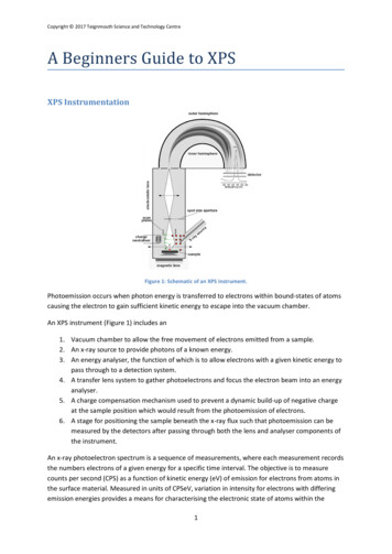
OM Book.book Page 13 Tuesday, September 25, 2012 2:30 PM3Base CoverWARNING: Before working inside your computer, read the safety information thatshipped with your computer and follow the steps in "Before You Begin" on page 9.For additional safety best practices information, see the Regulatory ComplianceHomepage at dell.com/regulatory compliance.Removing the Base Cover1 Close the display and turn the computer over.2 Using a Torx 5 screwdriver, remove the screws that secure the base cover tothe palm-rest assembly.3 Using your fingertips, lift the base cover starting from the back ofyour computer.4 Remove the base cover off the palm-rest assembly.11base cover22screws (10)Base Cover13
OM Book.book Page 14 Tuesday, September 25, 2012 2:30 PMReplacing the Base Cover1 Align the base cover with the palm-rest assembly and press the base coverinto place.2 Using a Torx 5 screwdriver, replace the screws that secure the base cover tothe palm-rest assembly.3 Follow the instructions in "After Working Inside Your Computer" on page 11.14Base Cover
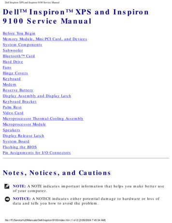
OM Book.book Page 15 Tuesday, September 25, 2012 2:30 PM4Power-Light BoardWARNING: Before working inside your computer, read the safety information thatshipped with your computer and follow the steps in "Before You Begin" on page 9.For additional safety best practices information, see the Regulatory ComplianceHomepage at dell.com/regulatory compliance.Prerequisites1 Remove the base cover. See "Removing the Base Cover" on page 13.Removing the Power-Light Board1 Lift the connector latch and pull the pull-tab to disconnect thepower-light board cable from the connector on the I/O board.2 Remove the screw that secures the power-light board to thepalm-rest assembly.3 Lift the power-light board off the palm-rest assembly.1231screw3power-light board2power-light board cablePower-Light Board15
OM Book.book Page 16 Tuesday, September 25, 2012 2:30 PMReplacing the Power-Light Board1 Align the screw hole on the power-light board with the screw hole onthe palm-rest assembly.2 Replace the screw that secures the power-light board to thepalm-rest assembly.3 Slide the power-light board cable into the system-board connectorand press down on the connector latch to secure the cable.Postrequisites1 Replace the base cover. See "Replacing the Base Cover" on page 14.2 Follow the instructions in "After Working Inside Your Computer" on page 11.16Power-Light Board
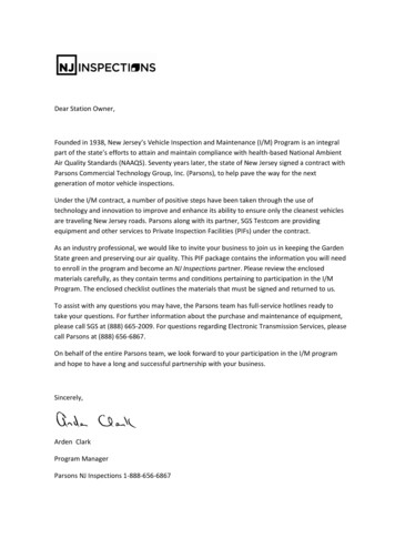
OM Book.book Page 17 Tuesday, September 25, 2012 2:30 PM5BatteryWARNING: Before working inside your computer, read the safety information thatshipped with your computer and follow the steps in "Before You Begin" on page 9.For additional safety best practices information, see the Regulatory ComplianceHomepage at dell.com/regulatory compliance.Prerequisites1 Remove the base cover. See "Removing the Base Cover" on page 13.2 Remove the power-light board. See "Removing the Power-Light Board" onpage 15.Removing the Battery1 Disconnect the battery cable from the system-board.2 Remove the screws that secure the battery to the palm-rest assembly.3 Lift the battery off the palm-rest assembly.1231screws (8)3battery cable2batteryBattery17
OM Book.book Page 18 Tuesday, September 25, 2012 2:30 PMReplacing the Battery1 Align the screw holes on the battery with the screw holes on thepalm-rest assembly.2 Replace the screws that secure the battery to the palm-rest assembly.3 Connect the battery cable to the system-board.Postrequisites1 Replace the power-light board. See "Replacing the Power-Light Board" onpage 16.2 Replace the base cover. See "Replacing the Base Cover" on page 14.3 Follow the instructions in "After Working Inside Your Computer" on page 11.18Battery
OM Book.book Page 19 Tuesday, September 25, 2012 2:30 PM6SpeakersWARNING: Before working inside your computer, read the safety information thatshipped with your computer and follow the steps in "Before You Begin" on page 9.For additional safety best practices information, see the Regulatory ComplianceHomepage at dell.com/regulatory compliance.Prerequisites1 Remove the base cover. See "Removing the Base Cover" on page 13.2 Remove the power-light board. See "Removing the Power-Light Board" onpage 15.3 Remove the battery. See "Removing the Battery" on page 17.Removing the SpeakersLeft Speaker1 Disconnect the I/O cable from the I/O board connector andsystem-board connector.1231I/O cable3system-board connector2I/O board connectorSpeakers19
OM Book.book Page 20 Tuesday, September 25, 2012 2:30 PM2 Disconnect the left-speaker cable from the I/O board connector.3 Release the Mini-Card cables from the routing guide on the left speaker.4 Remove the two screws that secure the left speaker to thepalm-rest assembly.5 Lift the left speaker off the palm-rest assembly.12201screws (2)3left-speaker cableSpeakers32routing guide
OM Book.book Page 21 Tuesday, September 25, 2012 2:30 PMRight Speaker1 Disconnect the right-speaker cable from the system-board connector.2 Remove the two screws that secure the right speaker to thepalm-rest assembly.3 Lift the right speaker off the palm-rest assembly.121screws (2)2right-speaker cableSpeakers21
OM Book.book Page 22 Tuesday, September 25, 2012 2:30 PMReplacing the SpeakersLeft Speaker1 Align the screw holes on the left speaker with the screw holes on thepalm-rest assembly.2 Replace the two screws that secure the left speaker to thepalm-rest assembly.3 Route the mini-card cables through the routing guide on the left speaker.4 Connect the left-speaker cable to the I/O board connector.5 Connect the I/O cable to the I/O board connector andsystem-board connector.Right Speaker1 Align the screw holes on the right speaker with the screw holes on thepalm-rest assembly.2 Replace the two screws that secure the right speaker to thepalm-rest assembly.3 Connect the right-speaker cable to the system-board connector.Postrequisites1 Replace the battery. See "Replacing the Battery" on page 18.2 Replace the power-light board. See "Replacing the Power-Light Board" onpage 16.3 Replace the base cover. See "Replacing the Base Cover" on page 14.4 Follow the instructions in "After Working Inside Your Computer" on page 11.22Speakers
OM Book.book Page 23 Tuesday, September 25, 2012 2:30 PM7Wireless Mini-CardWARNING: Before working inside your computer, read the safety information thatshipped with your computer and follow the steps in "Before You Begin" on page 9.For additional safety best practices information, see the Regulatory ComplianceHomepage at dell.com/regulatory compliance.NOTE: Dell does not guarantee compatibility or provide support for mini-cards fromsources other than Dell.If you ordered a wireless mini-card with your computer, the card isalready installed.Your computer has one half mini-card slot which supports a Wireless LocalArea Network (WLAN) Bluetooth combo card.Prerequisites1 Remove the base cover. See "Removing the Base Cover" on page 13.2 Remove the power-light board. See "Removing the Power-Light Board" onpage 15.3 Remove the battery. See "Removing the Battery" on page 17.4 Remove the right speaker. See "Removing the Speakers" on page 19.CAUTION: When the mini-card is not in the computer, store it in protectiveantistatic packaging. For more information, see "Protecting Against ElectrostaticDischarge" in the safety information that shipped with your computer.Wireless Mini-Card23
OM Book.book Page 24 Tuesday, September 25, 2012 2:30 PMRemoving the Mini-Card1 Disconnect the mini-card cables from the connectors on the mini-card.11mini-card cables (2)2 Remove the screw that secures the mini-card to the system board.3 Slide and remove the mini-card out of the system-board connector.123241screw3system-board connectorWireless Mini-Card2mini-card
OM Book.book Page 25 Tuesday, September 25, 2012 2:30 PMReplacing the Mini-Card1 Remove the new mini-card from its packaging.2 Align the notch on the mini-card with the tab in the system-board connector.CAUTION: Use firm and even pressure to slide the mini-card into place. If you useexcessive force, you may damage the connector.CAUTION: The connectors are keyed to ensure correct insertion. If you feelresistance, check the connectors on the mini-card and on the system board,and realign the mini-card.CAUTION: To avoid damage to the mini-card, never place cables underthe mini-card.3 Insert the mini-card connector at a 45-degree angle into thesystem-board connector.4 Press the other end of the mini-card down into the slot on thesystem board and replace the screw that secures the mini-card tothe system board.5 Connect the mini-card cables to the connectors on the mini-card.The following table provides the mini-card cable color scheme for theMini-Card supported by your computer.Connectors on the Mini-CardMini-Card Cable ColorSchemeWLAN Bluetooth (2 cables)Main WLAN Bluetooth (white triangle)whiteAuxiliary WLAN Bluetooth (black triangle) blackWireless Mini-Card25
OM Book.book Page 26 Tuesday, September 25, 2012 2:30 PMPostrequisites1 Replace the right speaker. See "Replacing the Speakers" on page 22.1 Replace the battery. See "Replacing the Battery" on page 18.2 Replace the power-light board. See "Replacing the Power-Light Board" onpage 16.3 Replace the base cover. See "Replacing the Base Cover" on page 14.4 Follow the instructions in "After Working Inside Your Computer" on page 11.26Wireless Mini-Card
OM Book.book Page 27 Tuesday, September 25, 2012 2:30 PM8Solid-State DriveWARNING: Before working inside your computer, read the safety informationthat shipped with your computer and follow the steps in "Before You Begin" onpage 9. For additional safety best practices information, see the RegulatoryCompliance Homepage at dell.com/regulatory compliance.CAUTION: To avoid data loss, do not remove the solid-state drive while thecomputer is On or in Sleep state.CAUTION: Solid-state drives are extremely fragile. Exercise care when handlingthe solid-state drive.Prerequisites1 Remove the base cover. See "Removing the Base Cover" on page 13.2 Remove the power-light board. See "Removing the Power-Light Board" onpage 15.3 Remove the battery. See "Removing the Battery" on page 17.Removing the Solid-State Drive1 Peel the tape that is adhered over the solid-state drive.11tape2 Remove the screw that secures the solid-state drive to the system board.Solid-State Drive27
OM Book.book Page 28 Tuesday, September 25, 2012 2:30 PM3 Slide and remove the solid-state drive out of the system-board connector.1231screw3solid-state drive2system-board connectorReplacing the Solid-State Drive1 Align the notch on the solid-state drive with the tab in thesystem-board connector.CAUTION: Use firm and even pressure to slide the solid-state drive into place.If you use excessive force, you may damage the connector.2 Insert the solid-state drive connector at a 45-degree angle into thesystem-board connector.3 Replace the screw that secures the solid-state drive to the system board.4 Adhere the tape over the solid-state drive.Postrequisites1 Replace the battery. See "Replacing the Battery" on page 18.2 Replace the power-light board. See "Replacing the Power-Light Board" onpage 16.3 Replace the base cover. See "Replacing the Base Cover" on page 14.4 Follow the instructions in "After Working Inside Your Computer" on page 11.28Solid-State Drive
OM Book.book Page 29 Tuesday, September 25, 2012 2:30 PM9Heat SinkWARNING: Before working inside your computer, read the safety information thatshipped with your computer and follow the steps in "Before You Begin" on page 9.For additional safety best practices information, see the Regulatory ComplianceHomepage at dell.com/regulatory compliance.Prerequisites1 Remove the base cover. See "Removing the Base Cover" on page 13.2 Remove the power-light board. See "Removing the Power-Light Board" onpage 15.3 Remove the battery. See "Removing the Battery" on page 17.Removing the Heat Sink1 In sequential order (indicated on the heat sink), remove the screws thatsecure the heat sink to the system board.2 Lift the heat sink off the system board.211heat sink2screws (4)Heat Sink29
OM Book.book Page 30 Tuesday, September 25, 2012 2:30 PMReplacing the Heat SinkNOTE: The original thermal grease can be reused, if the original system boardand heat sink are reinstalled together. If either the system board or the heat sinkis replaced, use the thermal pad provided in the kit to ensure that thermalconductivity is achieved.1 Clean the thermal grease from the bottom of the heat sink and reapply it.2 Align the screw holes on the heat sink with the screw holes on thesystem board.3 In sequential order (indicated on the heat sink), replace the screws thatsecure the heat sink to the system board.Postrequisites1 Replace the battery. See "Replacing the Battery" on page 18.2 Replace the power-light board. See "Replacing the Power-Light Board" onpage 16.3 Replace the base cover. See "Replacing the Base Cover" on page 14.4 Follow the instructions in "After Working Inside Your Computer" on page 11.30Heat Sink
OM Book.book Page 31 Tuesday, September 25, 2012 2:30 PM10FanWARNING: Before working inside your computer, read the safety information thatshipped with your computer and follow the steps in "Before You Begin" on page 9.For additional safety best practices information, see the Regulatory ComplianceHomepage at dell.com/regulatory compliance.Prerequisites1 Remove the base cover. See "Removing the Base Cover" on page 13.2 Remove the power-light board. See "Removing the Power-Light Board" onpage 15.3 Remove the battery. See "Removing the Battery" on page 17.Removing the Fan1 Disconnect the I/O cable from the I/O board connector and systemboard connector.3121I/O cable3system-board connector2I/O board connectorFan31
OM Book.book Page 32 Tuesday, September 25, 2012 2:30 PM2 Disconnect the power-adapter connector cable from thesystem-board connector.3 Release the power-adapter connector cable from the routing guideson the fan.211routing guides2power-adapter connector cable4 Disconnect the fan cable from the I/O board connector.5 Remove the screws that secure the fan to the palm-rest assembly.6 Lift the fan off the palm-rest assembly.123321fan cable3fanFan2screws (2)
OM Book.book Page 33 Tuesday, September 25, 2012 2:30 PMReplacing the Fan1 Align the screw holes on the fan with the screw holes on thepalm-rest assembly.2 Replace the screws that secure the fan to the palm-rest assembly.3 Connect the fan cable to the I/O board connector.4 Route the power-adapter connector cable through the routing guideson the fan.5 Connect the power-adapter connector cable to the system-board connector.6 Connect the I/O cable to the I/O board connector and system-boardconnector.Postrequisites1 Replace the battery. See "Replacing the Battery" on page 18.2 Replace the power-light board. See "Replacing the Power-Light Board" onpage 16.3 Replace the base cover. See "Replacing the Base Cover" on page 14.4 Follow the instructions in "After Working Inside Your Computer" on page 11.Fan33
OM Book.book Page 34 Tuesday, September 25, 2012 2:30 PM34Fan
OM Book.book Page 35 Tuesday, September 25, 2012 2:30 PMPower-Adapter Connector11WARNING: Before working inside your computer, read the safety information thatshipped with your computer and follow the steps in "Before You Begin" on page 9.For additional safety best practices information, see the Regulatory ComplianceHomepage at dell.com/regulatory compliance.Prerequisites1 Remove the base cover. See "Removing the Base Cover" on page 13.2 Remove the power-light board. See "Removing the Power-Light Board" onpage 15.3 Remove the battery. See "Removing the Battery" on page 17.4 Remove the speakers. See "Removing the Speakers" on page 19.Removing the Power-Adapter Connector1 Disconnect the mini-card cables from the connectors on the mini-card.2 Lift the connector latch and pull the pull-tab to disconnect the touchpadcable from the connector on the system board.3 Release the mini-card cables from the routing guides.Power-Adapter Connector35
OM Book.book Page 36 Tuesday, September 25, 2012 2:30 PM11routing guides3mini-card cables (2)232touchpad cable4 Disconnect the power-adapter connector cable from thesystem-board connector.5 Release the power-adapter connector cable from the routing guideson the fan.6 Remove the screw that secures the power-adapter connector to thepalm-rest assembly.7 Lift the power-adapter connector off the palm-rest assembly.36Power-Adapter Connector
OM Book.book Page 37 Tuesday, September 25, 2012 2:30 PM11routing guides3power-adapter connector cable223screwReplacing the Power-Adapter Connector1 Align the screw hole on the power-adapter connector with the screw holeon the palm-rest assembly.2 Replace the screw that secures the power-adapter connector to thepalm-rest assembly.3 Route the power-adapter connector cable through the routing guideson the fan.4 Connect the power-adapter connector cable to the system-board connector.5 Route the mini-card cables through the routing guides.6 Slide the touchpad cable into the system-board connector and pressdown on the connector latch to secure the cable.Power-Adapter Connector37
OM Book.book Page 38 Tuesday, September 25, 2012 2:30 PM7 Connect the mini-card cables to the connectors on the mini-card.The following table provides the mini-card cable color scheme for themini-card supported by your computer.Connectors on the Mini-CardMini-Card Cable ColorSchemeWLAN Bluetooth (2 cables)Main WLAN Bluetooth (white triangle)whiteAuxiliary WLAN Bluetooth (black triangle) blackPostrequisites1 Replace the speakers. See "Replacing the Speakers" on page 22.2 Replace the battery. See "Replacing the Battery" on page 18.3 Replace the power-light board. See "Replacing the Power-Light Board" onpage 16.4 Replace the base cover. See "Replacing the Base Cover" on page 14.5 Follow the instructions in "After Working Inside Your Computer" on page 11.38Power-Adapter Connector
OM Book.book Page 39 Tuesday, September 25, 2012 2:30 PMI/O Board12WARNING: Before working inside your computer, read the safety information thatshipped with your computer and follow the steps in "Before You Begin" on page 9.For additional safety best practices information, see the Regulatory ComplianceHomepage at dell.com/regulatory compliance.Prerequisites1 Remove the base cover. See "Removing the Base Cover" on page 13.2 Remove the power-light board. See "Removing the Power-Light Board" onpage 15.3 Remove the battery. See "Removing the Battery" on page 17.4 Remove the speakers. See "Removing the Speakers" on page 19.5 Remove the power-adapter connector. See "Removing the Power-AdapterConnector" on page 35.6 Remove the fan. See "Removing the Fan" on page 31.I/O Board39
OM Book.book Page 40 Tuesday, September 25, 2012 2:30 PMRemoving the I/O Board1 Remove the screw that secures the I/O board to the palm-rest assembly.2 Lift the I/O board off the palm-rest assembly.11I/O board22screwReplacing the I/O Board1 Align the screw holes on the I/O board with the screw holes on thepalm-rest assembly.2 Replace the screw that secure the I/O board to the palm-rest assembly.40I/O Board
OM Book.book Page 41 Tuesday, September 25, 2012 2:30 PMPostrequisites1 Replace the fan. See "Replacing the Fan" on page 33.2 Replace the power-adapter connector. See "Replacing the Power-AdapterConnector" on page 37.3 Replace the speaker
OM_Book.book Page 18 Tuesday, September 25, 2012 2:30 PM. Speakers 19 6 Speakers WARNING: Before working inside your computer, read the safety information that shipped with your computer and follow the steps in "Before You Begin" on page 9. 13. 13. computer.