Transcription
Bolting QuickReference Guiden Thread Lubricant Selectionn Bolting Installation Proceduren Hardware Selectionn Torque Charts
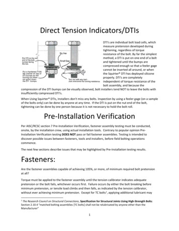
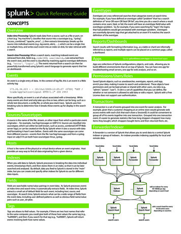
Thread Lubricant SelectionWhy Use Chesterton Thread Paste? Preserves bolt/stud integrity (controlled coefficient offriction [Kf-nut] at contact points) Accurate bolt/stud tension Insures correct flange sealing force Prevents thread galling Inhibits intergranular corrosion Safe operation of equipment Reduces disassembly timeChesterton Thread LubricantSelection GuideProduct KfMax TempWater pH Oil Steam Alloy710 0.20 1093 C (2000 F)B C CBC7250.18 1425 C (2600 F)BBBBA7720.16 1425 C (2600 F)BBBBA7830.16900 C (1650 F)AABAB7850.17 1204 C (2200 F)BBBAB785FG 0.20 1204 C (2200 F)BABBA7870.16540 C (1000 F)BCABC9000.16260 C (500 F)BBAAAKey: A Best, B Good, C FairAreas ofHigh StressabcExcess stress (a) without proper lubrication causes galling (b).This concentrates force and leads to thread fracture/seizure (c).Areas of high stress,shown in red,require use ofthread lubricants.Copyright 2014 László Molnár et al.23
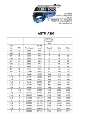
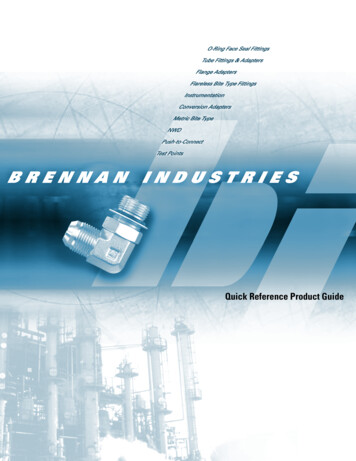
Bolting Installation ProcedureFlange and Bolt InstallationAll components must be correct to achieve a seal. The most commoncause of leaky gasketed joints is improper installation.1. Clean the flange faces and check for scars; the faces must be cleanand free of defects (burrs, pits, dents, etc.).2. Inspect all bolts and nuts for damaged or corroded threads.Remove burrs by “chasing” threads or wire brush to remove rust.Replace if components are heavily damaged.3. Lubricate, the full length of threads, the surface of the nut face adjacentto the flange or washer. Hardened washers are recommended.Assemble per diagram to the right.4. I nstall the new gasket and be sure gasket is properly centered.DO NOT REUSE old gasket. Use new gasket/gaskets only.5. C heck flange alignment. Flange faces must be parallel within 1/16''per foot of diameter, and flange bolt holes must be aligned towithin 1/8'' maximum offset.6. A djust the position of the nuts to insure that 2-3 threads are visibleabove the top of the nut.Recommended Tightening ProceduresUp to 8 Bolts– Use 4-Pass MethodPass 1: Set the torque wrench to the 30% torque value and apply thetorque wrench in the crisscross pattern for that particular flange untilall bolts have been tightened once.Pass 2: Set the torque wrench to the 60% torque value and repeat step 1.Pass 3: Set the torque wrench to the 100% torque value and repeatthe crisscross pattern a 3rd time.Pass 4: Check all bolts at 100% torque with a circular pattern.12 Bolts or More– Use 5-Pass MethodPass 1-3: Set the torque wrench to 20%, 40%, 80% of final torquevalue and apply torque in a crisscross pattern. Repeat until bolts havebeen successively tightened.Pass 4: Set the torque wrench to 100% torque value and repeatcrisscross pattern for a 4th time.Pass 5: Check all bolts at 100% torque with a circular pattern.4Bolt Tightening Sequence: Crisscross pattern: divide the flangeinto 4 quadrants. Over 40 bolts: tighten two adjacent bolts at thesame time.14BOLTS436121619311146710215 quadrant 1121313616920BOLTS4106142 quadrant 211241593415221913178 quadrant 258BOLTS428182124BOLTS371814106223191115 quadrant 4
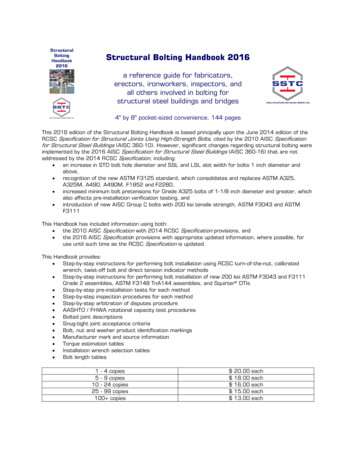
Hardware SelectionUseful Service Temperature Design LimitsGrade578B5B6SpecsSAE J429MaterialMedium CarbonSteelMinimumHeat TreatTempLowTempLimit*HighTempLimit*425 C(800 F)-45 C(-50 F)232 C(450 F)SAE J429Medium CarbonSteel425 C(800 F)-45 C(-50 F)232 C(450 F)SAE J429Medium CarbonAlloy Steel425 C(800 F)-45 C(-50 F)232 C(450 F)Cr-Mo Alloy Steel590 C(1100 F)-45 C(-50 F)400 C(750 F)Cr-Mo Alloy Steel590 C(1100 F)-45 C(-50 F)400 C(750 F)-45 C(-50 F)400 C(750 F)ASTM A193ASTM A193B7ASTM A193Cr-Mo Alloy Steel590 C(1100 F)B7MASTM A193Cr-Mo Alloy Steel620 C(1150 F)-45 C(-50 F)454 C(850 F)B8Class 1ASTM A193304 StainlessSteelNA-195 C(-320 F)593 C(1100 F)B8Class 2ASTM A193304 StainlessSteelNA-195 C(-320 F)593 C(1100 F)B8MClass 1ASTM A193316 StainlessSteelNA-195 C(-320 F)593 C(1100 F)B16ASTM A193Cr-Mo-Va AlloySteel650 C(1200 F)-45 C(-50 F)480 C(900 F)Live Loading Selection GuideDescription55005500I5505HMaterialStainless SteelAlloyInconelCarbon SteelColorGreyGreyBlackMax Temp C ( F)302 (575)704 (1300)593 e Range3/8'' to 2-3/4''(M8 to M64)3/8'' to 2-3/4''(M8 to M64)1/2'' to 3''(M16 to M72)RecommendedSize Range3/8'' to 1-1/8''(M8 to M30)3/8'' to 2-3/4''(M8 to M64)1-1/4'' to 3''(M33 to M72)Arrangement2 in parallel2 in parallelSingle DiscStress DesignsStandardStandard30K, 45K, 60KSTUDHEX BOLT* These values represent useful design limits. Use of these fastener materials close toor outside of these limits should be evaluated closely. Reference: Fastenal Company67
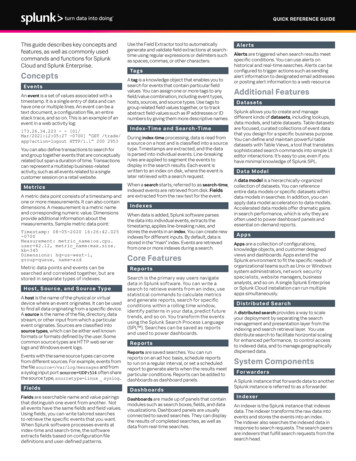
Torque ChartsCarbon/Carbon Alloy Torque Settings (FT-LBS)Bolt DiameterYield StrengthTensile 8"3"M76Grade 96.811444.813017.6Grade 813120.815021.317085.6Grade 3.214995.217167.219526.4Torque using Cf of 0.16 (783, 772, 787, 900). Add 10% for 725/785. Add 20% for 710.Ferretic Torque Settings (FT-LBS)Bolt DiameterB5B6Yield StrengthTensile Strength1/4"M65/16"M83/8"7/16" M101/2"M129/16" /8" M271-1/4" M301-3/8"1-1/2" M361-5/8"1-3/4" M421-7/8"2"M482-1/8"2-1/4" M562-3/8"2-1/2" M642-5/8"2-3/4" 9.67599.18873.010294.211871.213590.715458.4Torque using Cf of 0.16 (783, 772, 787, 900). Add 10% for 725/785. Add 20% for 710.89
Torque ChartsAustenitic Torque Wrench Settings (FT-LBS)Bolt DiameterYield StrengthTensile 8"M1611/16"3/4"M2013/16"7/8"M2215/16"1"M241-1/8" M271-1/4" M301-3/8"1-1/2" M361-5/8"1-3/4" M421-7/8"2"M482-1/8"2-1/4" M562-3/8"2-1/2" M642-5/8"2-3/4" M722-7/8"3"M76B8, B8M, (1 .84881.6B8-2, 745.8978.0Chesterton ISO certificates available onwww.chesterton.com/corporate/isoTechnical data reflects results of laboratory tests and is intended to indicate generalcharacteristics only. A.W. Chesterton Company disclaims all warranties express or implied,including warranties of merchantability and fitness for a particular purpose. Liability, if any, islimited to product replacement only. Any images contained herein are for general illustrativeor aesthetic purposes only and are not intended to convey any instructional, safety, handlingor usage information or advice respecting any product or equipment. Please refer to relevantSafety Data Sheets, Product Data Sheets, and/or Product Labels for safe use, storage, handling,and disposal of products, or consult with your local Chesterton sales representative.Torque using Cf of 0.16 (783, 772, 787, 900). Add 10% for 725/785. Add 20% for 710.*Tensile strength changed at bolt diameters.10The information contained in this document is for general guidance purposes only. It shouldnot be considered advice or a replacement for addressing equipment concerns or installationwith a qualified professional.11
GLOBAL SOLUTIONS, LOCAL SERVICESince its founding in 1884, A.W. Chesterton Company has successfullymet the critical needs of its diverse customer base. Today, as always,customers count on Chesterton solutions to increase equipmentreliability, optimize energy consumption, and provide local technicalsupport and service wherever they are in the world.Chesterton’s global capabilities include:nServicing plants in over 100 countriesnGlobal manufacturing operationsnMore than 500 Service Centers and Sales Offices worldwidenOver 1200 trained local Service Specialists and TechniciansVisit our website at chesterton.com 2017 A.W. Chesterton Company.trademark owned by A.W. Chesterton Company Registeredin USA and other countries, unless otherwise noted.A.W. Chesterton Company, 860 Salem Street, Groveland, MA 01834 USATelephone: 781-438-7000, Fax: 978-469-6528 chesterton.comForm No. EN36492Bolting Quick Reference Pocket Guide 09/17
Pass 1: Set the torque wrench to the 30% torque value and apply the torque wrench in the crisscross pattern for that particular flange until all bolts have been tightened once. Pass 2: Set the torque wrench to the 60% torque value and repeat step 1. Pass 3: Set the torque wrench to the 100% torque value and repeat the crisscross pattern a 3rd time.File Size: 369KBPage Count: 7