Transcription
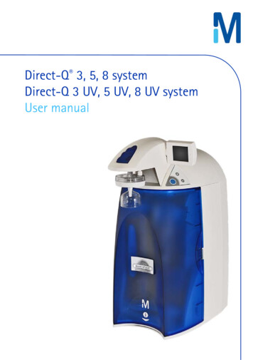
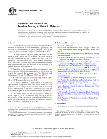
Direct Tension Indicators/DTIsDTI's are individual bolt load cells, whichmeasure pretension developed duringtightening, regardless of torqueresistance of the bolt. By far the simplestmethod, a DTI is put on one end of a boltand tightened until the bumps arecompressed enough so that a feeler gagecannot be inserted all around, or whenthe Squirter DTI has deployed siliconeproperly. DTI's are completelyindependent of torque resistance of thebolt assembly, and because thecompression of the DTI bumps can be visually observed, bolt installers tend NOT to leave the bolts withinsufficiently compressed DTI's.When Using Squirter DTIs, Installers don't miss any bolts. Inspection by using a feeler gage (on a sampleof the bolts only) can be done by anyone at any time. If the DTI is put on the nut end of the bolt,tightening can be done by one person because it is not necessary to hold the bolt roll.Pre-Installation VerificationPer AISC/RCSC section 7 Pre-Installation Verification, fastener assembly testing must be conducted,onsite, by the installation crew, using actual installation tools. Contrary to popular opinion PreInstallation Verification testing DOES NOT pass or fail fastener assemblies. Testing is intended todiscover possible issues between fasteners, tools and installers, before field bolting operationscommence.The next few sections describe issues that may be highlighted by Pre-Installation testing results.Fasteners:Are the fastener assemblies capable of achieving 105%, or more, of minimum required bolt pretensionat all?Torque must be applied to the fastener assembly until the tension calibrator indicates adequatepretension or the bolt fails, whichever occurs first. Failure occurs by either the bolt breaking beforeminimum pretension, or tensile load climbs and then falls, as indicated by the tension calibrator,without ever achieving minimum pretension. Except for TC bolts 1, applying additional lubricant mayThe Research Council on Structural Connections, Specification for Structural Joints Using High-Strength Bolts:Section 2.10.4 “matched bolting assemblies [TC bolts] shall not be relubricated by anyone other than theManufacturer”11
alleviate failure. However, if additional lubricant solves bolt failure, all fasteners represented bylubricated test samples, must be similarly lubricated.Tools:Do the installation tools have enough output torque to tighten adequately lubricated fastenerassemblies, to at least 105% of minimum required pretension?If the full effort of an installation tool applied to a fastener assembly, does not result in at least 105% ofrequired minimum pretension, the tool must be replaced for testing as well as for installation. Whilenot always true, an adequate installation tool should have a drive chuck at least as large as the fastenersbeing tightened. For example, when tightening ¾” bolts, the installation tool should have a square drivechuck of ¾” or more. Also, a tool’s manual may claim a higher output torque than the tool can produce.Such claims are usually stated vaguely, such as, claiming the tool’s motor can produce some highamount of torque. This statement may describe no-load torque output but once load is applied, thehigh torque described will not be realized.Installation crews:Do the installers understand how to employ the selected method?The installers must understand that a snugged tightened condition must be achieved before thepretensioning method is employed. Once a snug condition exists, the installers must fully understandthe method they employ and not confuse, or combine, fundamentals of individual methods. Such asapplying a torque value to compress a DTI or use a torque value as an inspection technique. Doing socombines elements of Calibrated Wrench and DTIs.Snug-Tightened Joints:Every bolted joint must be snug-tightened before a pretensioning method can be performed. Snugtighten is defined as the effort applied to bring the steel plies into firm contact. AISC/RCSC describes theeffort as the full effort of an ironworker or a few impacts of an impact wrench (section 8.1) until the nutcannot removed by hand. An attempt at manual nut removal is the only requirement for inspection(section 9.1). There is no pretension requirement for a “snugged” joint. Per AISC’s Specification forStructural Steel Buildings (AISC 360) Section J3:“There are no specific minimum or maximum tension requirements for snug-tight bolts.”With only hand tight as the inspection criteria, Snug-tight may begin with a pretension that is negligibleor zero.Conversely, snug-tightening may result in a pretension near or greater than the minimum required andmay strip or break the bolt. This is especially true of bolt diameters ¾” and below. Also, if the boltsurvives, a DTI will prematurely flatten and must be replaced before pretensioning begins.2
Verification BasicsThe following content applies to AISC/RCSC Pre-installation testing only. Individual projects, State DOTsand Federal Highway specifications may differ substantially and will not be covered here. The followingrepresents Applied Bolting Technology’s interpretation of AISC/RCSC Pre-installation testing based onThe Research Council on Structural Connections’, Specification for Structural Joints Using High-StrengthBolts (AISC 348) and the American Institute of Steel Construction’s Specification for Structural SteelBuildings (AISC 360). Anyone interested in a different interpretation is welcome to read the documentsthemselves.Verification testing can be summarized as snug-tightening, at least three sample fastener assemblies, inor with, a tension calibrator, applying the selected pretensioning method, and confirming at least 105%of minimum required pretension has been achieved. While each method accomplishes this withdifferent tools, fastener components, or tightening techniques, all 4 pretensioning methods follow thesebasic principles of snug fastener, apply method, and verify conformity to specification. Lastly, allacceptable methods are expected to permanently deform the fastener into its inelastic region 2.Sampling:Pre-Installation Verification testing begins with sampling. Per AISC/RCSC section 7.1:“On a sample of not fewer than three complete bolting assemblies of each combination ofdiameter, length, grade, and lot to be used in the work & Using bolting assemblies that arerepresentative of the condition of those that will be pretensioned in the work” (AISC/RCSC 16.252).Regardless of method, it is critical that assembly samples be TRULY REPRESENTATIVE, that is, in similarcondition as fasteners being actively pretensioned. Testing a “new” fastener, removed directly fromsealed shipping receptacles, does not constitute a representative sample, unless only new conditionfasteners are actively being pretensioned.Fasteners that have been snug-tightened & exposed to the weather, for any amount time, must beverified as is, if this condition accurately represents the fasteners’ being tightened in the steelwork.TRULY REPRESENTATIVE samples are especially important for TC bolts and Calibrated Wrenchinstallation and testing because these methods are negatively affected by weathering and lubricationdegradation.AISC/RCSC 16.2-47 “In any of the foregoing installation methods, it can be expected that a portion of the boltassembly (the threaded portion of the bolt within the grip length and/or the engaged threads of the nut and bolt)will reach the inelastic region of behavior. This permanent distortion has no undesirable effect on the subsequentperformance of the bolt.”23
Tension Calibrator StepsThe following lists the steps for both Standard (non-squirting) and Squirter type ASTM F959 DTIs1. Place each unique configuration of sample fastener assembly, containing a DTI, in a tensioncalibrator with washers placed in accordance with section 6.1, if necessary, and a washer againstthe DTI bumps.2. Snug the fastener in accordance with AISC/RCSC section 8.1 and inspect per section 9.1.3. Tighten the fastener assembly until the tension calibrator indicates 105% of the minimumrequired bolt pretension as listed in AISC/RCSC Table 5.2 or AISC 360 table J3.1M, asappropriate.4. Insert the appropriate feeler gauge into each available space between the DTI protrusions untilthe gauge physically touches the bolt shank. Each instance the feeler gauge fits between the DTIprotrusions, and touches the bolt shank, shall be known as an entry. Each time the feeler gaugedoes not touch the bolt shank, shall be known as a refusal.5. The number of entries may not be zero. Conversely, the number of refusals may not be 100%.In other words, a DTI must not be completely flattened at 105% of the minimum value listed inAISC/RCSC table 5.2 or AISC 360 table J3.1M.6. The number of entries/refusals defines the unique assembly’s test gap3 and Job Inspection Gap.7. Record the number of refusals as the baseline for field inspection. The number of refusalspermitted in the steelwork must be more than assembly’s test gap discovered duringverification. For example, if the test gap is defined as 0 refusals, out of a potential of 5, the JobInspection Gap shall be at least one additional refusal in the steelwork.8. If the number of entries equal zero and refusal count is 100% at 105% of the value in inAISC/RCSC table 5.2 or AISC 360 table J3.1M, consult the advisory section 4 of Applied BoltingTechnology’s website and apply the recommendation described therein.Bolting Methodology, non-squirting DTI1.2.Snug the steel plies, in as many steps as necessary, to bring the steel into firm contact asrequired by AISC/RCSC section 8.1, without compressing the DTI below the Job Inspection Gap.If the DTI is compressed below the Job inspection Gap, during the snugging operation, removeand replace the DTI.After snugging, apply enough torque to compress the DTI until the residual gap is less than theJob Inspection Gap.ASTM F959 Appendix X1. “The job inspection gap shall be a gap less than the measured DTI test gap at 1.05 theminimum required bolt tension.”AISC/RCSC 16.2-xi: Job Inspection Gap. A gap between a direct tension indicator and the hardened surface onwhich it bears that is less than the gap measured in a bolt tension measurement device when a tension equal to1.05 times the minimum required pretension is applied to the bolting s.php. Additional assistance is available by directly contacting AppliedBolting Technology via email at info@appliedbolting.com or calling 800 552-1999 or 802 460-3100.34
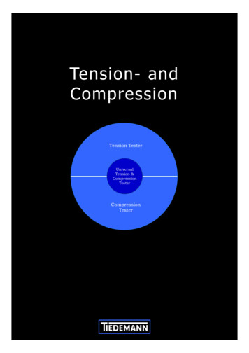
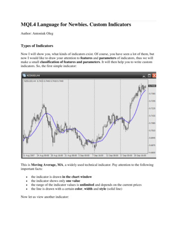
Bolting Methodology, Squirter DTI1.2.Snug the steel plies, in as many steps as necessary, to bring the steel into firm contact asrequired by AISC/RCSC section 8.1, without compressing the DTI below the Job Inspection Gap.If the DTI is compressed below the Job inspection Gap, during the snugging operation, removeand replace the DTI.After snugging, apply enough torque to compress the DTI until the orange Squirt indicationmedia is expelled from every available location and the residual gap is less than the JobInspection Gap.When inspecting non-squirting & Squirter DTIs the inspector MUST:1. Verify Pre-Installation Verification has been performed.2. Verify the joint has been snug-tightened.3. Verify the DTI bumps have not been compressed beyond the job inspection gap during thesnugging operation.4. Verify DTI bumps have been compressed below the job inspection gap after pretensioning.5. Accept any fastener with a pretension greater than the minimum required. 5When inspecting non-squirting & Squirter DTIs the inspector MUST NOT:1. Inspect DTI assemblies with a torque wrench.2. Compare the amount of turn between the nut and bolt with Turn-Of-Nut table 8.1.3. Reject DTIs that have been completely flattened during pretensioning.Minimum Bolt Pretension Per AISC/RCSC Table 5.2Bolt diameter, in.A325 boltsA490 bolts1 212155 819243 428357 8394951641 1 864801 1 4811021 3 8971211 1 21181481Equal to 0.70 times the minimum tensile strength of bolts as specified in ASTM F3125/F3125Mfor grades A325 and A490 bolts, with UNC threads, rounded to the nearest kip.AISC/RCSC 9.2.4 “A pretension that is greater than that specified in Table 5.2 or feeler gage refusal in all locations shall not because for rejection.”55
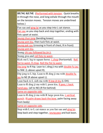
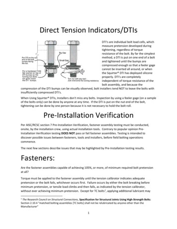
Minimum Bolt Pretension Per AISC 360, Table J3.1MBolt diameter, mmA325M boltsA490M 26408M36475595M16Equal to 0.70 times the minimum tensile strength of bolts, as specified in ASTM F3125/F3125Mfor grades A325M and A490M bolts, with MC threads, rounded to the nearest kN.6
Pre-Installation Verification Test Teportusing Direct Tension IndicatorsDate:Wrench Model:Skidmore No.:Bolt Grade:Bolt Size:Skidmore Calibration Date:ASTM A325ASTM A490BLACKGALVANIZEDDACROMETLot No.:DTI Lot & config.:DTI ON NUT SIDEDTI ON HEAD SIDENut lot number:F436 FW:F436 Wide FW:Required Tension:(5% over minimum tension)(7/8" Minimum 39 kips, 5% over 41 kips)Sample #1.005"Bolt Tension.015"Sample CCEPTABLEYesNoRefusalsASSEMBLYACCEPTABLEYesNoBolt TensionSample #3Bolt TensionInspector:Date:
applying a torque value to compress a DTI or use a torque value as an inspection technique. Doing so combines elements of Calibrated Wrench and DTIs. Snug-Tightened Joints: Every bolted joint must be snug-tightened before a pretensioning method can be performed. Snug-tighten is defined as the effort applied to bring the steel plies into firm contact