Transcription
T R A N Q U I L I T Y 2 7 T W O - S TA G E ( T T ) S E R I E SSIZE 026 - 072 (7.0kW - 19.3kW)H O R I Z O N TA L , V E R T I C A L & D O W N F L O WR 4 1 0 A - 6 0 H z S TA N D A R D & E X T E N D E D R A N G E
S E I R E S ) T T ( E G AT S - O W T 7 2 Y T I L I U Q N A R T)Wk3.91 - Wk0.7( 270 - 620 EZISW O L F N W O D & L A C I T R E V , L AT N O Z I R O HE G N A R D E D N E T X E & D R A D N AT S z H 0 6 - A 0 1 4 R
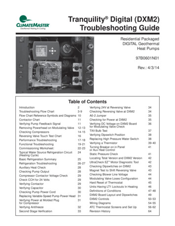
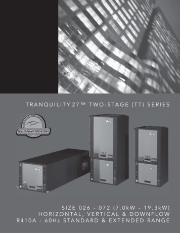
THE SMART SOLUTION FOR ENERGY EFFICIENCYTr a n q u i l i t y 2 7 Tw o - S t a g e ( T T ) S e r i e sR e v. : 0 5 / 2 2 / 0 7 DTHE TRANQUILITY 27 TWO-STAGE (TT) SERIESUNIT FEATURESAs the highest efficiency water-source heat pump on theplanet, the Tranquility 27 series raises the bar for watersource heat pump efficiencies, features and applicationflexibility. Not only does the Tranquility 27 far exceedASHRAE 90.1 efficiencies, but it also uses EarthPure HFC-410A zero ozone depletion refrigerant, making it anextremely environmentally-friendly option. Tranquility 27 is eligible for additional LEED (Leadership in Energyand Environmental Design) points because of its “green”technology design. Sizes 026 (2 ton, 7.0 kW) through 072 (6 tons, 19.3 kW) EarthPure HFC-410A refrigerant Copeland UltraTech two-stage unloadingscroll compressors GE ECM variable speed fan motor with soft start Exceeds ASHRAE 90.1 efficiencies Part load operation significantly lowers annualoperating costs Galvanized steel construction with attractive black matpolyester powder coat paint and silver accents Stainless steel drain pan Foil-backed insulation in air handler section Unique double isolation compressor mounting withvibration isolation springs for quiet operation Insulated divider and separate compressor/airhandler compartments TXV metering device Extended range (20 to 120 F, -6.7 to 48.9 C) operation Microprocessor controls standard (optional DXM and/orDDC controls) LonWorks, BACnet, Modbus and Johnson N2compatibility options for DDC controls Field convertible discharge air arrangement forhorizontal units Low profile slanted control box for easy access Internally trapped condensate drain line (verticalunits only) Flush securely-mounted corner post water connections(no backup wrench required) Unit Performance Sentinel performancemonitoring system Eight Safeties Standard Wide variety of options including ClimaDry modulatingreheat, e-coated air coils and internal pumpsAvailable in sizes 2 tons (7.0 kW) through 6 tons (19.3 kW)with multiple cabinet options (vertical upflow, verticaldownflow and horizontal) the Tranquility 27 offers a widerange of units for most any installation. The Tranquility27 has an extended range refrigerant circuit, capableof ground loop (geothermal) applications as well as waterloop (boiler-tower) applications. Standard features aremany. Copeland UltraTech two-stage unloading scrollcompressor, GE ECM variable fan motor, microprocessorcontrols, galvanized steel cabinet, polyester powder coatpaint, stainless steel drain pan and foil-backed air handlerinsulation are just some of the features of the innovativeTranquility 27 series.ClimateMaster’s exclusive double isolation compressormounting system makes the Tranquility 27 the quietestunit on the market. Compressors are mounted onvibration isolation springs to a heavy gauge mountingplate, which is then isolated from the cabinet basewith rubber grommets for maximized vibration/soundattenuation. The unique low profile slanted control boxmakes installing and maintaining the unit easier than anyother water-source heat pump currently in production.Options such as e-coated air coil, DDC controls, internalpump and high efficiency MERV 11 two-inch (51mm) airfilters allow customized design solutions.The Tranquility 27 (TT) Series water-source heat pumpsare designed to meet the challenges of today’s HVACdemands with one of the most innovative productsavailable on the market.w w w. c l i m a t e m a s t e r. c o mTT3
C L I M AT E M A S T E R W AT E R - S O U R C E H E AT P U M P STr a n q u i l i t y 2 7 Tw o - S t a g e ( T T ) S e r i e sR e v. : 0 5 / 2 3 / 0 7 DSelection ProcedureReference CalculationsHeatingHELWT EWT GPM x 500LAT EAT HCCFM x1.08CoolingHRLWT EWT GPM x 500LAT (DB) EAT (DB) -LC TC - SCSCCFM x1.08S/T SCTCLegend and Glossary of AbbreviationsBTUH BTU( British Thermal Unit) per hourCFM airflow, cubic feet/minuteCOP coefficient of performance BTUH output/BTUH inputDB dry bulb temperature ( F)EAT entering air temperature, Fahrenheit (dry bulb/wet bulb)EER energy efficiency ratio BTUH output/Watt inputEPT external pipe threadESP external static pressure (inches w.g.)EWT entering water temperatureGPM water flow in U.S. gallons/minuteHE total heat of extraction, BTUHHC air heating capacity, BTUHHR total heat of rejection, BTUHHWCIPTKWLATLCLWTMBTUHS/TSCTCWBWPD hot water generator (desuperheater) capacity, Mbtuh internal pipe thread total power unit input, kilowatts leaving air temperature, F latent cooling capacity, BTUH leaving water temperature, F 1000 BTU per hour sensible to total cooling ratio sensible cooling capacity, BTUH total cooling capacity, BTUH wet bulb temperature ( F) waterside pressure drop (psi & ft. of hd.)Conversion Table - to convert inch-pound (English) to SI (Metric)TT4Air FlowWater FlowExt Static PressureWater Pressure DropAirflow (L/s) CFM x 0.472Water Flow (L/s) gpm x 0.0631ESP (Pa) ESP (in of wg) x 249PD (kPa) PD (ft of hd) x 2.99C l i m a t e M a s t e r W a t e r- S o u r c e H e a t i n g a n d C o o l i n g S y s t e m s
THE SMART SOLUTION FOR ENERGY EFFICIENCYTr a n q u i l i t y 2 7 Tw o - S t a g e ( T T ) S e r i e sR e v. : 0 5 / 2 2 / 0 7 DSelection ProcedureStep 1 Determine the actual heating and cooling loads at thedesired dry bulb and wet bulb conditions.Step 2 Obtain the following design parameters: Entering watertemperature, water flow rate in GPM, air flow in CFM,water flow pressure drop and design wet and dry bulbtemperatures. Air flow CFM should be between 300 and450 CFM per ton. Unit water pressure drop should bekept as close as possible to each other to make waterbalancing easier. Go to the appropriate tables and findthe proper indicated water flow and water temperature.Step 3 Select a unit based on total and sensible coolingconditions. Select a unit which is closest to, but nolarger than, the actual cooling load.Step 4 Enter tables at the design water flow and watertemperature. Read the total and sensible coolingcapacities (Note: interpolation is permissible,extrapolation is not).Step 5 Read the heating capacity. If it exceeds the designcriteria it is acceptable. It is quite normal for WaterSource Heat Pumps to be selected on cooling capacityonly since the heating output is usually greater than thecooling capacity.Step 6 Determine the correction factors associated with thevariable factors of dry bulb and wet bulb (page 14).Corrected Total Cooling tabulated total cooling x wet bulb correction.Corrected Sensible Cooling tabulated sensible cooling x wet/dry bulb correction.Step 7 Compare the corrected capacities to the loadrequirements. Normally if the capacities are within 10%of the loads, the equipment is acceptable. It is betterto undersize than oversize, as undersizing improveshumidity control, reduces sound levels and extends thelife of the equipment.Step 8 When completed, calculate water temperature riseand assess the selection. If the units selected are notwithin 10% of the load calculations, then review whateffect changing the GPM, water temperature and/or airflow and air temperature would have on the correctedcapacities. If the desired capacity cannot be achieved,select the next larger or smaller unit and repeat theprocedure. Remember, when in doubt, undersizeslightly for best performance.Example Equipment Selection For CoolingStep 1 Load Determination:Assume we have determined that the appropriate cooling loadat the desired dry bulb 80 F and wet bulb 65 F conditions isas follows:Total Cooling . 22,100 BTUHSensible Cooling . 16,500 BTUHEntering Air Temp. 80 F Dry Bulb / 65 F Wet BulbStep 2 Design Conditions:Similarly, we have also obtained the following design parameters:Entering Water Temp . 90 FWater Flow (Based upon 10 F rise in temp.) 6.0 GPMAir Flow . 730 CFMStep 3, 4 & 5 HP Selection:After making our preliminary selection (TTH026 - Full Load), weenter the tables at design water flow and water temperature andread Total Cooling, Sens. Cooling and Heat of Rej. capacities:Total Cooling . 24,200 BTUHSensible Cooling . 16,300 BTUHHeat of Rejection . 29,900 BTUHStep 6 & 7 Entering Air and Airflow Corrections:Next, we determine our correction factors.TableEnt Air Air Flow CorrectedCorrected Total Cooling 24,200 x 0.975 x 0.978 23,076Corrected Sens Cooling 16,300 x 1.096 x 0.926 16,543Corrected Heat of Reject 29,900 x 0.979 x 0.978 28,628Step 8 Water Temperature Rise Calculation & Assessment:Actual Temperature Rise9.5 FWhen we compare the Corrected Total Cooling and CorrectedSensible Cooling figures with our load requirements statedin Step 1, we discover that our selection is within /- 10% ofour sensible load requirement. Furthermore, we see that ourCorrected Total Cooling figure is within 1,000 Btuh the actualindicated load.w w w. c l i m a t e m a s t e r. c o mTT5
C L I M AT E M A S T E R W AT E R - S O U R C E H E AT P U M P STr a n q u i l i t y 2 7 Tw o - S t a g e ( T T ) S e r i e sR e v. : 0 5 / 2 3 / 0 7 DTT Series Nomenclature1 234 5 67891011 12131415TT V 0 2 6 A G C 3 0 C L K SModel TypeStandardTT TranquilityTwo-Stage ScrollS StandardSupply Air & Motor OptionConfigurationOption Supply ConfigurationTopKTTVNTTDDownPTTHBackWTTHStraightV Vertical UpflowH HorizontalD Vertical DownflowUnit Size026038049064072MotorECMECMECMECMReturn AirL Left ReturnR Right ReturnHeat Exchanger & Valve OptionsRevision LevelA Current RevisionVoltageG 208-230/60/1H 208-230/60/3F 460/60/3ControlsC CXMD DXML CXM w/LONM DXM w/LONN CXM w/MPCP DXM w/MPCStandardClimaDry ReheatMotorized ValveNon Coated Air CoilCoated Air CoilCopper Cupro-Nickel Copper Cupro-NickelCNAJEPDFTSUWWater Circuit Options0 None2 HWG (Coil Only)5 Secondary Circulating Pump6 HWG (Coil Only) w/Auto Flow Regulator 2.5 GPM/Ton7 HWG (Coil Only) w/Auto Flow Regulator 3.0 GPM/Ton8 Auto Flow Regulator 2.5 GPM/Ton9 Auto Flow Regulator 3.0 GPM/TonCabinet Insulation1 Extended Range2 Extended Range w/UltraQuiet3 Standard Range4 Standard Range w/UltraQuietRev.: 03/02/06DTT6C l i m a t e M a s t e r W a t e r- S o u r c e H e a t i n g a n d C o o l i n g S y s t e m s
THE SMART SOLUTION FOR ENERGY EFFICIENCYTr a n q u i l i t y 2 7 Tw o - S t a g e ( T T ) S e r i e sR e v. : 0 5 / 2 2 / 0 7 DPerformance DataARI/ASHRAE/ISO 13256-1ASHRAE/ARI/ISO 13256-1. English (IP) UnitsWater Loop Heat TH/V/D072CapacityModulationCooling 86 FGround Water Heat PumpHeating 68 FCooling 59 FGround Loop Heat PumpHeating 50 FCoolingFull Load 77 FPart Load 68 FHeatingFull Load 32 FPart Load 41 57,70021.445,4003.9Cooling capacities based upon 80.6 F DB, 66.2 F WB entering air temperatureHeating capacities based upon 68 F DB, 59 F WB entering air temperatureGround Loop Heat Pump ratings based on 15% antifreeze solutionAll ratings based upon operation at lower voltage of dual voltage rated modelsASHRAE/ARI/ISO 13256-1. Metric (SI) UnitsWater Loop Heat PumpModelCapacityModulationCooling 30 CGround Water Heat PumpHeating 20 CCooling 15 CGround Loop Heat PumpHeating 10 CCoolingFull Load 25 CPart Load 20 CHeatingFull Load 0 CPart Load 5 ,9106.313,3063.9Cooling capacities based upon 27 C DB, 19 C WB entering air temperatureHeating capacities based upon 20 C DB, 15 C WB entering air temperatureGround Loop Heat Pump ratings based on 15% antifreeze solutionAll ratings based upon operation at lower voltage of dual voltage rated modelsw w w. c l i m a t e m a s t e r. c o mTT7
C L I M AT E M A S T E R W AT E R - S O U R C E H E AT P U M P STr a n q u i l i t y 2 7 Tw o - S t a g e ( T T ) S e r i e sR e v. : 0 5 / 2 3 / 0 7 DPerformance DataSelection NotesFor operation in the shaded area when water is usedin lieu of an anti-freeze solution, the LWT (LeavingWater Temperature) must be calculated. Flow must bemaintained to a level such that the LWT is maintainedabove 40 F [4.4*C] when the JW3 jumper is not clipped(see example below). This is due to the potential of therefrigerant temperature being as low as 32 F [0 C] with40 F [4.4 C] LWT, which may lead to a nuisance cutoutdue to the activation of the Low Temperature Protection.JW3 should never be clipped for standard rangeequipment or systems without antifreeze.Example:At 50 F EWT (Entering Water Temperature) and 1.5 gpm/ton, a 3 ton unit has a HE of 22,500 Btuh. To calculateLWT, rearrange the formula for HE as follows:HE TD x GPM x 500, where HE Heat of Extraction(Btuh); TD temperature difference (EWT - LWT) andGPM U.S. Gallons per Minute.Heating - EAT 70 0.733.433.434.134.125.925.928.628 9.520.420.621.221 .161.121.181.141.181.151.181.151.211.181.221 .213.514.514.815.215.515.415.716.516.817.317 2.189.293.990.894.891.695.191.996.693.297.794 .304.474.564.754.734.934.784.984.935.135.105 31TD HE / (GPM x 500)TD 22,500 / (4.5 x 500)TD 10 FLWT EWT - TDLWT 50 - 10 40 FIn this example, as long as the EWT does not fall below 50 F, the system will operate as designed. For EWTs below50 F, higher flow rates will be required (open loop systems, for example, require at least 2 gpm/ton when EWT isbelow 50 F).TT8C l i m a t e M a s t e r W a t e r- S o u r c e H e a t i n g a n d C o o l i n g S y s t e m s
THE SMART SOLUTION FOR ENERGY EFFICIENCYTr a n q u i l i t y 2 7 Tw o - S t a g e ( T T ) S e r i e sR e v. : 0 5 / 2 2 / 0 7 DPerformance DataTTH/V/D 026 (Part Load)725 CFM Nominal (Rated) Airflow Cooling, 825 CFM Nominal (Rated) Airflow HeatingWPDEWT 55.5Performance capacities shown in thousands of BtuhCooling - EAT 80/67 20725620725TCSCSens/TotRatiokWHeating - EAT 70 0Operation00 not 0000000000000000Interpolation is permissible; extrapolation is not.All entering air conditions are 80 F DB and 67 F WB in cooling, and 70 F DB in heating.ARI/ISO certified conditions are 80.6 F DB and 66.2 F WB in cooling and 68 F DB in heating.Table does not reflect fan or pump power corrections for ARI/ISO conditions.All performance is based upon the lower voltage of dual voltage rated units.Performance stated is at the rated power supply; performance may vary as the power supply varies from the rated.Operation below 40 F EWT is based upon a 15% antifreeze solution.Operation below 60 F EWT requires optional insulated water/refrigerant circuit.See performance correction tables for operating conditions other than those listed above.See Performance Data Selection Notes for operation in the shaded areas.w w w. c l i m a t e m a s t e r. c o mTT9
C L I M AT E M A S T E R W AT E R - S O U R C E H E AT P U M P STr a n q u i l i t y 2 7 Tw o - S t a g e ( T T ) S e r i e sR e v. : 0 5 / 2 3 / 0 7 DPerformance DataTTH/V/D 026 (Full Load)850 CFM Nominal (Rated) Airflow Cooling, 950 CFM Nominal (Rated) Airflow HeatingWPDEWT .26.96.9Performance capacities shown in thousands of BtuhCooling - EAT 80/67 30850730850TCSCSens/TotRatiokWHeating - EAT 70 Interpolation is permissible; extrapolation is not.All entering air conditions are 80 F DB and 67 F WB in cooling, and 70 F DB in heating.ARI/ISO certified conditions are 80.6 F DB and 66.2 F WB in cooling and 68 F DB in heating.Table does not reflect fan or pump power corrections for ARI/ISO conditions.All performance is based upon the lower voltage of dual voltage rated units.Performance stated is at the rated power supply; performance may vary as the power supply varies from the rated.Operation below 40 F EWT is based upon a 15% antifreeze solution.Operation below 60 F EWT requires optional insulated water/refrigerant circuit.See performance correction tables for operating conditions other than those listed above.See Performance Data Selection Notes for operation in the shaded 000000000000000000000000Operation00 not recommended0000000000000000000000000000000000C l i m a t e M a s t e r W a t e r- S o u r c e H e a t i n g a n d C o o l i n g S y s t e m 5.52000000000000000000
THE SMART SOLUTION FOR ENERGY EFFICIENCYTr a n q u i l i t y 2 7 Tw o - S t a g e ( T T ) S e r i e sR e v. : 0 5 / 2 2 / 0 7 DPerformance DataTT H/V/D 038 (Part Load)1000 CFM Nominal (Rated) Airflow Cooling, 1000 CFM Nominal (Rated) Airflow HeatingWPDEWT 8.04.04.06.06.08.08.04.04.06.06.08.08.0Performance capacities shown in thousands of BtuhCooling - EAT 80/67 6010008601000SCSens/TotRatiokWHeating - EAT 70 FTC00000Operationnot .3102.030.01.6224.897.830.91.6825.4103.231.21.6325
ClimateMaster Water-Source Heating and Cooling Systems CLIMATEMASTER WATER-SOURCE HEAT PUMPS Tranquility 27 Two-Stage (TT) Series Rev.: 05/23/07D TT 4 Air Flow Water Flow Ext Static Pressure Water Pressure Drop Airflow (L/s) CFM x 0.472 Water Flow (L/s) gpm x 0.0631 ESP (Pa) ESP (in of wg) x 249 PD (kPa) PD (ft of hd) x 2.99