Transcription
Tranquility 16(TC) SeriesTable of ContentsCommercial Horizontal& Vertical PackagedWater-Source Heat Pumps50HZ-HFC-410AINSTALLATION, OPERATION& MAINTENANCE97B0075N02Revised: 25 July, 2017Model NomenclatureGeneral InformationUnit Physical DataHorizontal InstallationField Conversion of Air DischargeHorizontal InstallationDuct System InstallationVertical InstallationPiping InstallationWater-Loop Heat Pump ApplicationsGround-Loop Heat Pump ApplicationsGround-Water Heat Pump ApplicationsWater Quality StandardsElectrical - Line VoltageElectrical - Power WiringElectrical - Power & Low Voltage WiringElectrical - Low Voltage WiringElectrical - Thermostat WiringTypical Wiring DiagramsCXM ControlsDXM ControlsCXM and DXM ControlsOperating LimitsPiping System Cleaning and FlushingUnit Starting and Operating ConditionsUnit Start-Up ProcedurePreventive MaintenanceFunctional TroubleshootingPerformance TroubleshootingFunctional Troubleshooting - S-I UnitsWarrantyRevision 04142444546474852
CLIMATEMASTER WATER-SOURCE HEAT PUMPSTr a n q u i l i t y 1 6 ( T C ) S e r i e sR e v. : 2 5 J u l y, 2 0 1 7This Page Intentionally Left Blank2C l i m a t e M a s t e r W a t e r- S o u r c e H e a t P u m p s
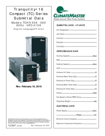
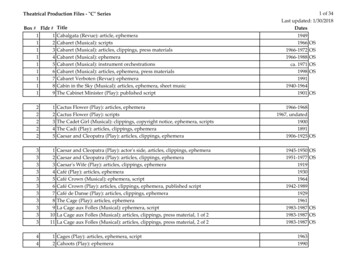
THE SMART SOLUTION FOR ENERGY EFFICIENCYTr a n q u i l i t y 1 6 ( T C ) S e r i e sR e v. : 2 5 J u l y, 2 0 1 7Model NomenclatureGeneral Overview12TC34 5 6789101112131415H036AUF30ALBSS STANDARDMODEL TYPESUPPLY AIR OPTIONSTC TRANQUILITY COMPACT (HFC-410A)B BACK DISCHARGE, HORIZONTAL ONLYY BACK DISCHARGE, HIGH STATICHORIZONTAL 015 - 060T TOP DISCHARGE, VERTICAL ONLYV TOP DISCHARGE, HIGH STATICVERTICAL 015 - 060S STRAIGHT DISCHARGE, HORIZONTAL ONLYZ STRAIGHT DISCHARGE, HIGH STATICHORIZONTAL 015 - 060CONFIGURATIONH HORIZONTALV VERTICALUNIT SIZE006 - V009 - V012 -V015 - V018 - V024 - V030 - V, U036 - V, U042 - U048 - U060 - URETURN AIR OPTIONSL LEFT RETURNR RIGHT RETURNF FRONT RETURN, VERTICAL 009 - 030V LEFT RETURN S.S. DRAIN PANW RIGHT RETURN S.S. DRAIN PANZ FRONT RETURN S.S. DRAIN PAN,VERTICAL 009-030HEAT EXCHANGER OPTIONSA Copper Water Coil w/Coated Air CoilC Copper Water Coil w/Non-Coated Air CoilJ Cupro-nickel Water Coil w/Coated Air CoilN Cupro-nickel Water Coil w/Non-Coated Air CoilREVISION LEVELA CURRENT REVISION FOR ALL SIZESVOLTAGEV 220/240/50/1U 380/420/50/3{CEAPPROVEDFUTURE USE0 NONECONTROLSCABINET INSULATIONF CXMG DXMH CXM w/LONJ DXM w/LONT CXM w/MPCU DXM w/MPC1 EXTENDED RANGE2 EXTENDED RANGE w/ULTRA QUIET3 STANDARD RANGE4 STANDARD RANGE w/ULTRA QUIETc l i m a t e m a s t e r. c o m3
CLIMATEMASTER WATER-SOURCE HEAT PUMPSTr a n q u i l i t y 1 6 ( T C ) S e r i e sR e v. : 2 5 J u l y, 2 0 1 7General InformationSafteyWarnings, cautions, and notices appear throught thismanual. Read these items carefully before attemptingany installation, service, or troubeshooting of theequipment.DANGER: Indicates an immediate hazardous situation,which if not avoided will result in death or serious injury.DANGER labels on unit access panels must be observed.WARNING!WARNING! All refrigerant discharged from this unit mustbe recovered WITHOUT EXCEPTION. Technicians mustfollow industry accepted guidelines and all local, state,and federal statutes for the recovery and disposal ofrefrigerants. If a compressor is removed from this unit,refrigerant circuit oil will remain in the compressor. Toavoid leakage of compressor oil, refrigerant lines of thecompressor must be sealed after it is removed.WARNING: Indicates an immediate hazardous situation,which if not avoided will result in death or serious injury. InspectionUpon receipt of the equipment, carefully check theCAUTION: Indicates a potentially hazardous situationshipment against the bill of lading. Make sure all unitsor an unsafe practice, which if not avoided could resulthave been received. Inspect the packaging of eachin minor or moderate injury with product or propertyunit, and inspect each unit for damage. Ensure thatdamage.the carrier makes proper notation of any shortages ordamage on all copies of the freight bill and completesNOTICE: Notification of installation, operation, or main- a common carrier inspection report. Concealedtenance information, which is important, but which is not damage not discovered during unloading musthazard-related.be reported to the carrier within 15 days of receiptof shipment. If not filed within 15 days, the freightcompany can deny the claim without recourse. Note: Itis the responsibility of the purchaser to file all necessaryclaims with the carrier. Notify your equipment supplierof all damage within fifteen (15) days of shipment.WARNING!WARNING! The EarthPure Application and ServiceManual should be read and understood before attemptingto service refrigerant circuits with HFC-410A.WARNING!WARNING! To avoid the release of refrigerant into theatmosphere, the refrigerant circuit of this unit must beserviced only by technicians who meet local, state, andfederal proficiency requirements.CAUTION!CAUTION! To avoid equipment damage, DO NOT usethese units as a source of heating or cooling during theconstruction process. The mechanical components andfilters will quickly become clogged with construction dirtand debris, which may cause system damage.WARNING!WARNING! This appliance is not intended for use bypersons (including children) with reduced physical,sensory, or mental capabilities, or lack of experience andknowledge, unless they have been given supervision orinstruction concerning use of the appliance by a personresponsible for their safety.4StorageEquipment should be stored in its original packaging ina clean, dry area. Store units in an upright position at alltimes. Stack units a maximum of 3 units high.Unit ProtectionCover units on the job site with either the originalpackaging or an equivalent protective covering.Cap the open ends of pipes stored on the job site.In areas where painting, plastering, and/or sprayinghas not been completed, all due precautions mustbe taken to avoid physical damage to the units andcontamination by foreign material. Physical damageand contamination may prevent proper start-up andmay result in costly equipment clean-up.Examine all pipes, fittings, and valves before installingany of the system components. Remove any dirt ordebris found in or on these components.C l i m a t e M a s t e r W a t e r- S o u r c e H e a t P u m p s
THE SMART SOLUTION FOR ENERGY EFFICIENCYTr a n q u i l i t y 1 6 ( T C ) S e r i e sR e v. : 2 5 J u l y, 2 0 1 7Pre-InstallationInstallation, Operation, and Maintenance instructionsare provided with each unit. Horizontal equipmentis designed for installation above false ceiling or in aceiling plenum. Other unit configurations are typicallyinstalled in a mechanical room. The installation sitechosen should include adequate service clearancearound the unit. Before unit start-up, read all manualsand become familiar with the unit and its operation.Thoroughly check the system before operation.Prepare units for installation as follows:1. Compare the electrical data on the unitnameplate with ordering and shippinginformation to verify that the correct unit has beenshipped.2. Keep the cabinet covered with the originalpackaging until installation is complete and allplastering, painting, etc. is finished.3. Verify refrigerant tubing is free of kinks or dentsand that it does not touch other unit components.4. Inspect all electrical connections. Connectionsmust be clean and tight at the terminals.5. Remove any blower support packaging (water-toair units only).6. Loosen compressor bolts on units equipped withcompressor spring vibration isolation until thecompressor rides freely on the springs. Removeshipping restraints.7. Some airflow patterns are field convertible(horizontal units only). Locate the airflowconversion section of this IOM.8. Locate and verify any hot water generator (HWG),hanger, or other accessory kit located in thecompressor section or blower section.CAUTION!CAUTION! All three phase scroll compressors must havedirection of rotation verified at start-up. Verification isachieved by checking compressor Amp draw. Amp drawwill be substantially lower compared to nameplate values.Additionally, reverse rotation results in an elevated soundlevel compared to correct rotation. Reverse rotation willresult in compressor internal overload trip within severalminutes. Verify compressor type before proceeding.CAUTION!CAUTION! DO NOT store or install units in corrosiveenvironments or in locations subject to temperature orhumidity extremes (e.g., attics, garages, rooftops, etc.).Corrosive conditions and high temperature or humidity cansignificantly reduce performance, reliability, and servicelife. Always move and store units in an upright position.Tilting units on their sides may cause equipment damage.CAUTION!CAUTION! CUT HAZARD - Failure to follow this cautionmay result in personal injury. Sheet metal parts may havesharp edges or burrs. Use care and wear appropriateprotective clothing, safety glasses and gloves whenhandling parts and servicing heat pumps.NOTICE! Failure to remove shipping brackets fromspring-mounted compressors will cause excessivenoise, and could cause component failure due toadded vibration.c l i m a t e m a s t e r. c o m5
CLIMATEMASTER WATER-SOURCE HEAT PUMPSTr a n q u i l i t y 1 6 ( T C ) S e r i e sR e v. : 2 5 J u l y, 2 0 1 7Tranquility 16 (TC) Series (50 Hz)TC Series006009012015018024030036RotaryCompressor (1 7 x 127127 x 127152 x 127254 x 254279 x Coax Volume ir Coil Dimensions (H x W) mm254 x 381254x381254 x 381508 x 438508 x 438508 x 438508 x 438610 x 552610 x 552610 x 718610 x 718Filter Standard - 25.4mmThrowaway mm254 x 457254x457254 x 457508 x 508508 x 508508 x 508508 x 508610 x 610610 x 6101-356 x 610,1- 457 x 6101-356 x 610,1- 457 x 610Weight - Operating kg474852697286899299119126Weight - Packaged kg5152567274889295102123129254 x 381254 x 381254 x 381406 x 559406 x 559406 x 559406 x 559508 x 635508 x 635508 x 889508 x 889508 x 711 or(2) 508 x 3561-508 x 610,1-508 x 3561-508 x 610,1-508 x 356Factory Charge HFC-410A - kgPSC Fan Motor & BlowerFan Motor Type/SpeedsFan Motor (Watts)Blower Wheel Size (Dia x w) mm203 x 178229 x 178229 x 203Water Connection SizeVerticalHorizontalAir Coil Dimensions (H x W) mm254 x 457254 x 457254 x 457406 x 635406 x 635457 x 635457 x 635508 x 711 or(2) 508 x 356Weight - Operating kg474752697286899299119138Weight - Packaged kg5152567274889295102123141Filter Standard - 25.4mmThrowaway mmNotes:All units have dual isolation compressor mounts for quiet operation, thermal expansion valves for refrigerant metering, and 22.2mm & 28.6mm electricalknockouts to accommodate field wiring.FPT - Female Pipe ThreadCondensate Drain Connection is 3/4” FPTUnit Maximum Water Working PressureOptionsBase Unit6Max Pressure kPa3447C l i m a t e M a s t e r W a t e r- S o u r c e H e a t P u m p s
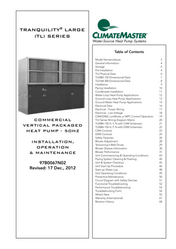
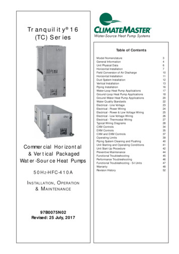
THE SMART SOLUTION FOR ENERGY EFFICIENCYTr a n q u i l i t y 1 6 ( T C ) S e r i e sR e v. : 2 5 J u l y, 2 0 1 7Horizontal InstallationHorizontal Unit LocationUnits are not designed for outdoor installation. Locatethe unit in an INDOOR area that allows enough spacefor service personnel to perform typical maintenanceor repairs without removing unit from the ceiling.Horizontal units are typically installed above a falseceiling or in a ceiling plenum. Never install units inareas subject to freezing or where humidity levels couldcause cabinet condensation (such as unconditionedspaces subject to 100% outside air). Considerationshould be given to access for easy removal of the filterand access panels. Provide sufficient room to makewater, electrical, and duct connection(s).If the unit is located in a confined space, such as acloset, provisions must be made for return air to freelyenter the space by means of a louvered door, etc. Anyaccess panel screws that would be difficult to removeafter the unit is installed should be removed prior tosetting the unit. Refer to Figure 3 for an illustration ofa typical installation. Refer to unit submittal data orengineering design guide for dimensional data.In limited side access installations, pre-removal of thecontrol box side mounting screws will allow control boxremoval for future servicing.Conform to the following guidelines when selectingunit location:1. Provide a hinged access door in concealed-splineor plaster ceilings. Provide removable ceilingtiles in T-bar or lay-in ceilings. Refer to horizontalunit dimensions for specific series and modelin unit submittal data. Size the access openingto accommodate the service technician duringthe removal or replacement of the compressor,control, or blower assembly. Provide access tohanger brackets, water valves and fittings. Providescrewdriver clearance to access panels, dischargecollars and all electrical connections.2. DO NOT obstruct the space beneath the unitwith piping, electrical cables and other items thatprohibit future removal of components or the unititself.3. Use a manual portable jack/lift to lift and supportthe weight of the unit during installation andservicing.Mounting Horizontal UnitsHorizontal units have 4 hanger brackets partiallyattached at the factory, one at each corner. Enclosedwithin the unit there is a hanger kit hardware bagcontaining vibration isolation grommets, washers,screws and a hanger installation instruction page. Oneadditional screw from the hardware bag must be addedto each hanger bracket before unit installation.Tighteneach screw to 75 in-lbs (8.5 Nm). See Figure 1. Referto the hanger installation instruction page containedin the hardware bag for details of final hanger bracketattachment and unit suspension. See Figure 1a
climatemaster.com 5 Tranquility 16 (TC) Series Rev.: 25 July, 2017 NOTICE! Failure to remove shipping brackets from spring-mounted compressors will cause excessive noise, and could cause component failure due to added vibration. CAUTION! All three phase scroll compressors must have direction of rotation verifi ed at start-up. Verifi cation is achieved by checking compressor Amp draw. Amp .