Transcription
TRANQUILITY LARGE(TL) SERIESTable of ContentsCOMMERCIALVERTICAL PACKAGEDHEAT PUMP - 50HZINSTALLATION,OPERATION& MAINTENANCE97B0067N02Revised: 17 Dec., 2012Model NomenclatureGeneral InformationStoragePre-InstallationTLV Physical DataTLV084-150 Dimensional DataTLV168-300 Dimensional DataInstallationPiping InstallationCondensate InstallationWater-Loop Heat Pump ApplicationsGround-Loop Heat Pump ApplicationsGround-Water Heat Pump ApplicationsElectrical DataElectrical - Power WiringElectrical - Low VoltageCXM/DXM, LonWorks or MPC Control OperationTLV Series Wiring Diagram MatrixTLV084-150 H, F, N with CXM SchematicTLV084-150 H, F, N with DXM SchematicCXM ControlsDXM ControlsSafety FeaturesBlower AdjustmentTensioning V-Belt DrivesBlower Sheave InformationBlower PerformanceUnit Commissioning & Operating ConditionsPiping System Cleaning & FlushingUnit & System CheckoutUnit Start Up ProcedureStart-up Sheet LogUnit Operating ConditionsPreventive MaintenanceCircuit Diagram with Safety DevicesFunctional TroubleshootingPerformance TroubleshootingTroubleshooting FormWhat’s NewWarranty (International)Revision 0314344454648495051525354556768
CLIMATEMASTER WATER-SOURCE HEAT PUMPSTr a n q u i l i t y L a r g e ( T L ) S e r i e sRevised: 17 Dec., 2012This Page Intentionally Left Blank2C l i m a t e M a s t e r W a t e r- S o u r c e H e a t P u m p s
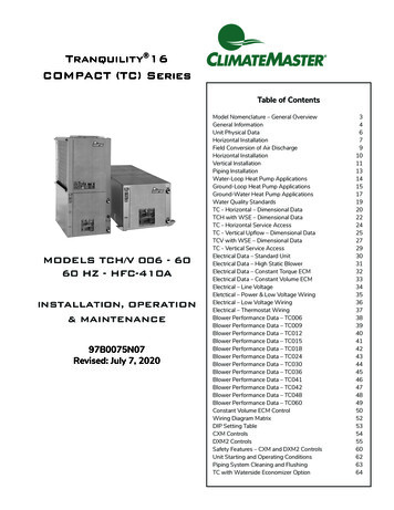
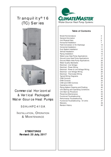
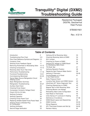
THE SMART SOLUTION FOR ENERGY EFFICIENCYTr a n q u i l i t y L a r g e ( T L ) S e r i e sRevised: 17 Dec., 2012Model Nomenclature1234 5 678910111213 1415TLV096AUF1AC BT SSPECIAL OPTIONSMODEL TYPETL TRANQUILITY LARGE COMMERCIALS STANDARDA DUAL POINT POWERB HOT GAS BYPASSC DUAL POINT POWER HOT GAS BYPASSCONFIGURATIONV VERTICALUNIT SIZE084096120150168192240300AIR FLOW OPTIONSBF BACK RETURN / FRONT SUPPLYBT BACK RETURN / TOP SUPPLYFB FRONT RETURN / BACK SUPPLYFT FRONT RETURN / TOP SUPPLYYF BACK RETURN / FRONT SUPPLY SS DRAIN PANYT BACK RETURN / TOP SUPPLY SS DRAIN PANZB FRONT RETURN / BACK SUPPLY SS DRAIN PANZT FRONT RETURN / TOP SUPPLY SS DRAIN PANREVISION LEVELA CURRENTVOLTAGEU 380-420/50/3 - R410A{CE APPROVEDEUROPEHEAT EXCHANGER /MOTORIZED VALVE OPTIONSCONTROLSF CXMG DXMH CXM w/ LONJ DXM w/ LONT CXM w/ MPCU DXM w/ MPCCOPPER CUPRONICKEL NON COATEDOPTION WATER COIL WATER COILAIR COILACABINET INSULATION / FILTER RACKOPTIONRANGEULTRA QUIET1ANO1” FILTER RACK 2” FILTER RACK 4” FILTER WSNONOYESYESNONOYESNOCOATED MTRZD VALVEAIR COIL ( WATER OUT NOYESNOBCYESYESNONOYESYESNONOYESNONOYESBLOWER DRIVE PACKAGEA STANDARD RPM & STANDARD MOTORB LOW & RPM & STANDARD MOTORC HIGH RPM & STANDARD MOTORE HIGH RPM & LARGE MOTORc l i m a t e m a s t e r. c o m3
CLIMATEMASTER WATER-SOURCE HEAT PUMPSTr a n q u i l i t y L a r g e ( T L ) S e r i e sRevised: 17 Dec., 2012StoragePre-InstallationGeneral InformationSafetyWarnings, cautions, and notices appearthroughout this manual. Read these items carefullybefore attempting any installation, service, ortroubleshooting of the equipment.DANGER: Indicates an immediate hazardoussituation, which if not avoided will result in death orserious injury. DANGER labels on unit access panelsmust be observed.WARNING: Indicates a potentially hazardoussituation, which if not avoided could result in death orserious injury.CAUTION: Indicates a potentially hazardous situationor an unsafe practice, which if not avoided couldresult in minor or moderate injury or product orproperty damage.NOTICE: Notification of installation, operation, ormaintenance information, which is important, butwhich is not hazard-related.WARNING!WARNING! The EarthPure Application and ServiceManual should be read and understood before attemptingto service refrigerant circuits with HFC-410A.WARNING!WARNING! To avoid the release of refrigerant into theatmosphere, the refrigerant circuit of this unit must beserviced only by technicians who meet local, state, andfederal proficiency requirements.CAUTION!CAUTION! To avoid equipment damage, DO NOT usethese units as a source of heating or cooling during theconstruction process. The mechanical components andfilters will quickly become clogged with construction dirtand debris, which may cause system damage.WARNING!WARNING! The installation of water-source heat pumpsand all associated components, parts, and accessorieswhich make up the installation shall be in accordancewith the regulations of ALL authorities having jurisdictionand MUST conform to all applicable codes. It is theresponsibility of the installing contractor to determine andcomply with ALL applicable codes and regulations.WARNING!WARNING! All refrigerant discharged from this unit mustbe recovered WITHOUT EXCEPTION. Technicians mustfollow industry accepted guidelines and all local, state,and federal statutes for the recovery and disposal ofrefrigerants. If a compressor is removed from this unit,refrigerant circuit oil will remain in the compressor. Toavoid leakage of compressor oil, refrigerant lines of thecompressor must be sealed after it is removed.Inspection - Upon receipt of the equipment, carefullycheck the shipment against the bill of lading. Make sureall units have been received. Inspect the packaging ofeach unit, and inspect each unit for damage. Insure thatthe carrier makes proper notation of any shortages ordamage on all copies of the freight bill and completes acommon carrier inspection report. Concealed damagenot discovered during unloading must be reported tothe carrier within 15 days of receipt of shipment. If notfiled within 15 days, the freight company can deny theclaim without recourse. Note: It is the responsibility ofthe purchaser to file all necessary claims with the carrier.Notify your equipment supplier of all damage withinfifteen (15) days of shipment.Storage - Equipment should be stored in its originalpackaging in a clean, dry area. Store units in anupright position at all times.Unit Protection - Cover units on the job site with eitherthe original packaging or an equivalent protectivecovering. Cap the open ends of pipes stored on thejob site. In areas where painting, plastering, and/orspraying has not been completed, all due precautionsmust be taken to avoid physical damage to the unitsand contamination by foreign material. Physical damageand contamination may prevent proper start-up and mayresult in costly equipment clean-up.Examine all pipes, fittings, and valves before installingany of the system components. Remove any dirt ordebris found in or on these components.Pre-Installation - Installation, Operation, andMaintenance instructions are provided with each unit.Horizontal equipment is designed for installationabove false ceiling or in a ceiling plenum. Other unitconfigurations are typically installed in a mechanicalroom. The installation site chosen should includeadequate service clearance around the unit. Beforeunit start-up, read all manuals and become familiarwith the unit and its operation. Thoroughly check thesystem before operation.4C l i m a t e M a s t e r W a t e r- S o u r c e H e a t P u m p s
THE SMART SOLUTION FOR ENERGY EFFICIENCYTr a n q u i l i t y L a r g e ( T L ) S e r i e sRevised: 17 Dec., 2012General InformationPrepare units for installation as follows:1. Compare the electrical data on the unit nameplatewith ordering and shipping information to verifythat the correct unit has been shipped.2. Keep the cabinet covered with the originalpackaging until installation is complete and allplastering, painting, etc. is finished.3. Verify refrigerant tubing is free of kinks or dentsand that it does not touch other unit components.4. Inspect all electrical connections. Connectionsmust be clean and tight at the terminals.5. Some airflow patterns and some control boxlocations are field convertible. Locate theconversion section of this IOM.CAUTION!CAUTION! All three phase scroll compressors must havedirection of rotation verified at start-up. Verification isachieved by checking compressor Amp draw. Amp drawwill be substantially lower compared to nameplate values.Additionally, reverse rotation results in an elevated soundlevel compared to correct rotation. Reverse rotation willresult in compressor internal overload trip within severalminutes. Verify compressor type before proceeding.CAUTION!CAUTION! DO NOT store or install units in corrosiveenvironments or in locations subject to temperature orhumidity extremes (e.g., attics, garages, rooftops, etc.).Corrosive conditions and high temperature or humidity cansignificantly reduce performance, reliability, and servicelife. Always move and store units in an upright position.Tilting units on their sides may cause equipment damage.CAUTION!CAUTION! CUT HAZARD - Failure to follow this cautionmay result in personal injury. Sheet metal parts may havesharp edges or burrs. Use care and wear appropriateprotective clothing, safety glasses and gloves whenhandling parts and servicing heat pumps.c l i m a t e m a s t e r. c o m5
CLIMATEMASTER WATER-SOURCE HEAT PUMPSTr a n q u i l i t y L a r g e ( T L ) S e r i e sRevised: 17 Dec., 2012TLV Physical DataModel084096120150168192Scroll (1)Compressor QuantityFactory Charge HFC-410a [kg]per circuit2403006.357.03Scroll (2)3.974.426.357.033.974.42Standard Motor [kw].751.121.492.241.492.243.733.73Large Motor [kw]1.121.492.243.732.243.735.605.60Blower MotorBlower Motor Quantity1BlowerNo. of Blowers1Blower Wheel Size D x W [cm]238.1 x 27.938.1 x 38.138.1 x 27.938.1 x 38.1Water Connection SizeFPT (in) [mm]1-1/2" [38.1]2" [50.8]2-1/2" [63.5]Coax VolumeVolume [liters]8.289.3713.1118.2924.0827.98Condensate Connection SizeFPT (in) [mm]1" [25.4]Air Coil DataAir Coil Dimensions H x W [cm]91.4 x 121.9291.4 x 121.91.11Air Coil Total Face Area [m ]2.22Air Coil Tube Size [cm]3/8" [0.953]Air Coil Fin Spacing [fins per cm]5.5Air Coil Number of Rows4.722345.524.7234Miscellaneous DataFilter Standard - [25.4mm]Throwaway (qty) [cm](4) 45.74 x 63.5(8) 45.74 x 63.5Weight - Operating [kg]399422435725755769Weight - Packaged [kg]406429442739769782All units have grommet compressor mountings, and 2.2 cm & 3.49cm electrical knockouts.Unit Maximum Water Working PressureOptionsMax Pressure [kPa]Base Unit2,068Motorized Water Valve2,068Internal Secondary Pump999Use the lowest maximum pressure rating when multiple options are combined.6C l i m a t e M a s t e r W a t e r- S o u r c e H e a t P u m p s
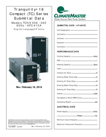
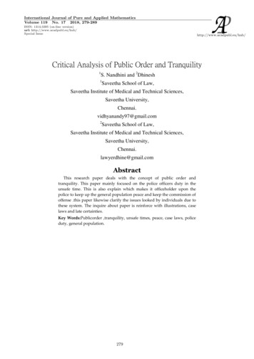
THE SMART SOLUTION FOR ENERGY EFFICIENCYTr a n q u i l i t y L a r g e ( T L ) S e r i e sRevised: 17 Dec., 2012TLV084-150 Dimensional DataALL CONFIGURATIONS REQUIRE SERVICE ACCESS AREADESCRIBED IN NOTES 7, 8, 9, AND 10.19.3FDB19.3FBSPAIR OUTAIR OUTBSPUPATBSPNRPBLOWERROTATIONRETURN AIRRETURN AIRSC41Q4NRP3Control BoxCAP MSP02Control Box433PN014235MKKCSP CAP MSPLALM1NRPCSPNOTE 5REAR RETURN TOP DISCHARGE (RR/TD)12345NRP25URFRONT RETURN TOP DISCHARGE (FR/TD)NOTES:1. All dimensions in cm.2. Water inlet and water outlet connections are available on either side (left or right) of the unit. Installermust plug water inlet/outlet not being connected to.3. Condensate drain is available on either side (left or right) of unit. Drain hose and drain connection will betied inside the unit. Installer will untie the drain hose, form trap, and connect to the condensate drain holeof installer’s choice.4. Electrical access is available on either side (left or right) of unit and is also available in the front on the leftor right side of the unit.5. Overall Depth - Add 8 cm for 2.5 cm or 5 cm Filter Rack; 5.12” for 4” filter rack and for FD, RD additional2.7cm for supply air duct flange.6. Overall cabinet height dimension does not include duct flange when in top discharge configuration.7. While access to all removable panels may not be required, installer should take care to comply with allbuilding codes and allow adequate clearance for future field service.8. Units require 91 cm clearance for water connections, CAP, CSP, MSP and BSP service access.9. Side service access must be 9.4 cm on any side that connections are made. If no connections are madeon a side then service access can be 1.5 cm minimum.10. Filter removal is from bottom of frame, allow 9.4 cm access for servicing.LEGENDTLV084-120 TLV150Water Inlet (See Note 2)1-1/2” FPT2” FPT1-1/2” FPTWater Outlet (See Note 2)2” FPTCondensate Drain (See Note 3)1” FPT3.49 cmHigh Voltage Access (See Note 4)Low Voltage Access (See Note 4)2.2 cmBSP - Blower Service PanelCAP - Control Access PanelCSP - Compressor Access PanelMSP - Motor Service PanelNRP - Non Removable PanelUPA - Upper Pulley Access4.3FDRETURN AIRBSPFEBSPBSPAIR OUTAIR OUTNRP415NRPNRP34CAP MSPRETURN AIR(See Notes 7 and 10)425342NRP4Control Box54Control Box344CSPOverall CabinetSERVICE ACCESS91 CMFRONT AND BACK(See Notes 7 and 8)Model084 -120 cm.150cm.ABCDischarge ConnectionsDuct FlangeDEF3CSP CAP MSPSide Service Access(See Notes 7 and 9)REAR RETURN FRONT DISCHARGE (RR/FD)51NRPFRONT RETURN REAR DISCHARGE (FR/RD)Water ectrical KnockoutsNO1O2PQRReturn Air ConnectionsUsing Return Air OpeningSTUVDepthNote 5WidthHeightNote .72.57.6121.982.2113.36.9c l i m a t e m a s t e r. c o mReturn ReturnDepth Height7
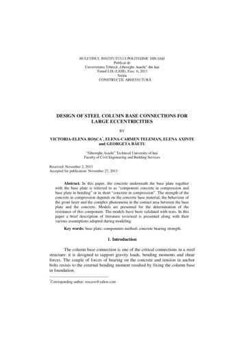
CLIMATEMASTER WATER-SOURCE HEAT PUMPSTr a n q u i l i t y L a r g e ( T L ) S e r i e sRevised: 17 Dec., 2012TLV168-300 Dimensional DataALL CONFIGURATIONS REQUIRE SERVICE ACCESS AREADESCRIBED IN NOTES 7, 8, 9, AND 10.V19.3FD19.3BGDAIR OUTAIR OUTEBSPRETURN AIRNRPCBSPFAIR OUTAIR OUTETBSPUPARETURN AIRSRETURN AIR1QBSP3RETURN AIRS5MSP02BLOWERROTATION24013 Control Box4URPNRPNRPCAPControl Box4CSP CAP213CSP54NCSP MSPMCSPLKKANOTE 5FRONT RETURN TOP DISCHARGE (FR/TD)REAR RETURN TOP DISCHARGE (RR/TD)NOTES:1. All dimensions in cm.2.
TRANQUILITY LARGE (TL) SERIES . Electrical Data 16 Electrical - Power Wiring 17 Electrical - Low Voltage 18 CXM/DXM, LonWorks or MPC Control Operation 19 TLV Series Wiring Diagram Matrix 20 TLV084-150 H, F, N with CXM Schematic 21 TLV084-150 H, F, N with DXM Schematic 22 CXM Controls 23 DXM Controls 24 Safety Features 26 Blower Adjustment 28 Tensioning V-Belt Drives 29 Blower