Transcription
SpiderViewDigital Holter RecorderUSER MANUAL
TABLE OF CONTENTS1.INTRODUCTION . 51.1.Use in the United States. 52.SPIDERVIEW PRESENTATION. 62.1.Intended use. 62.2.Specific features of SpiderView. 62.3.Packaging. 63.USER PROFILE . 73.1.Training . 74.PRECAUTIONS FOR USE AND MAINTENANCE . 84.1.Transportation . 84.2.End of service. 84.3.Conditions for use and storage of the device and flash cards. 84.4.Electromagnetic compatibility. 94.5.Care of the device and flash card. 95.WARRANTY. 106.GENERAL DESCRIPTION . 116.1.SpiderView components. 116.2.Description of symbols on the case and packaging . 126.3.Opening the battery cover . 136.4.Cable insertion and extraction. 137.USE OF BATTERIES. 147.1.Batteries . 147.2.Rechargeable batteries . 147.3.Internal memory battery . 148.POSITIONING THE ELECTRODES . 158.1.Two-channel recording (3 electrodes). 158.2.Two channel recording (5 electrodes) . 168.3.Three channel recording (7 electrodes) . 178.4.XYZ channel recording (7 electrodes). 188.5.Twelve-lead recording* (10 electrodes). 189.USING THE PROGRAMMING BUTTONS . 209.1.User interface structure . 209.2.Starting the device. 2010.STARTING THE HOLTER RECORDING . 2210.1. Programming using the buttons . 2211.DEVICE PARAMETERS . 28SpiderView – UA10709B3
11.1. Voltage screen . 2811.2. Impedance screen. 2811.3. Time and date screen. 2911.4. About screen . 2912.SPECIAL FUNCTIONING MODES AND ERROR MESSAGES. 3012.1. List of error messages. 3013.TECHNICAL SPECIFICATIONS. 3213.1. Type . 3213.2. Number of leads . 3213.3. Electrical characteristics. 3213.4. Mechanical characteristics . 3213.5. Acquisition characteristics . 3213.6. Radio Equipment Emission . 3314.ACCESSORIES . 3415.APPENDIX . 3515.1. Guidance and manufacturer's declaration: electromagnetic emissions . 3515.2. Guidance and manufacturer's declaration: cable length . 3515.3. Guidance and manufacturer's declaration: electromagnetic emissions . 3615.4. Guidance and manufacturer's declaration: electromagnetic Immunity. 3615.5. SpiderView and mobiles (recommendations). 3915.6. CANADA . 3915.7. UNITED STATES . 394SpiderView – UA10709B
1. INTRODUCTION1.INTRODUCTIONThis icon is used to draw your attention to a particularly important point.This icon alerts you to a hazard that may result in equipment damage or personal injury.Carefully read the instructions provided with this icon.USE IN THE UNITED STATESUSAonly1.1.SpiderView – UA10709B[CAUTION: Federal law restricts the sale of this device by or on the order of a physician.]5
2. SPIDERVIEW PRESENTATION2.SPIDERVIEW PRESENTATION2.1.INTENDED USESpiderView is a digital ECG Holter recorder intended for long-term ambulatory ECGrecordings, multi-channel, and High-Resolution ECG recordings.WARNING: The holter analyzing SyneScope software is needed to download and analyzethe recordings.2.2.SPECIFIC FEATURES OF SPIDERVIEWSpiderView uses flash cards: MMC cards (Multi Media Cards), SD cards (Secured Data) orMicroSD cards.SpiderView is not compatible with the ELATEC and SyneView analysis software systems.SpiderView recordings longer than 24h and with more than 3 channels must be read withSyneScope.SpiderView 24h recordings, 2/3 channels can be read with SyneScope, SyneTec,EasyScope, SyneView2 and SyneCom.TYPE OF RECORDINGSpiderView offers three types of recording:― Holter recording only.― High-Resolution ECG recording only.― High-Resolution ECG recording followed by a 24-hour standard Holter recording.RECORDING QUALITYSpiderView offers 24-hour Holter recordings in three different formats:― Standard quality: standard bandwidth. Smaller file size (approx. 5MB per channel).― High quality: wide bandwidth. Mid-range file size (approx. 10MB per channel).― Uncompressed: wide bandwidth (file size: 17.3 MB per channel).2.3.PACKAGINGSpiderView is supplied in a case containing:― one SpiderView device― one 1.5 V AA lithium battery― one reusable bag and strap― one disposable bag― one Bluetooth dongle― bag of 30 single-use electrodes― Spiderview, HookUp Go and MyRhythm Pro user manuals on CD-Rom― HookUp Go Software on CD-Rom― RED compliance leaflet6SpiderView – UA10709B
3. USER PROFILE3.USER PROFILE3.1.TRAININGAny person who has followed the training required by the local regulatory authority. Trainingcompletion and effectiveness are under his/her medical supervisor’s responsibility.NOTE: Any serious incident that has occurred in relation to the device must be reported toMicroPort CRM S.r.l. and your competent authority.SpiderView – UA10709B7
4. PRECAUTIONS FOR USE AND MAINTENANCE4.PRECAUTIONS FOR USE AND MAINTENANCE4.1.TRANSPORTATIONSpiderView is packaged for delivery as outlined in the packaging chapter.If you want to repack and carry or deliver the SpiderView after its first usage, we recommendputting all the parts back into their initial positions.Please take care putting the flash card case into the appropriate place.Flash cards can be sent by postal service. They are light and extremely strong. Nevertheless,it is recommended that they be bubble-wrapped and sent in a double envelope.When storing the device and the accessories, the SpiderView case can be stored upright orlying down.4.2.END OF SERVICEWhen SpiderView reaches the end of its service life, it should be returned to MicroPort forappropriate recycling.The batteries should be recycled as appropriate.ECG cables and pouch can be thrown away, since they do not contain specific dangerousmaterials. SpiderView parts and accessories do not contain mercury or mercury compounds.4.3.CONDITIONS FOR USE AND STORAGE OF THE DEVICE AND FLASHCARDSThe following table shows the conditions for use, storage and transportation for 0 to 45 C10% to 95% non condensing700 hPA to 1060 hPaStorage andTransportation-20 to 65 C5%* to 93% non condensing500 hPA to 1060 hPa(*: Flash cards 8%)If exposed to a severely wet or humid environment, a protective bag like RG008 is needed.During transportation or storage for a prolonged period, remove the battery from the device.WARNING: If a leak or a powdery deposit is visible on the battery, in the compartment or onthe electrical contacts, remove the battery and dispose of it following local environmentallegislation and/or the intended procedures. If the leak is not significant (no oxidation onthe electrical contacts of the battery), it is possible to clean it with a damp cloth, andthen carefully dry the cleaned parts. In the event of traces of significant oxidation, it isstrongly recommended not to use the device (risk of recording failure) and return it toMicroPort After Sales. Repair is excluded from the warranty and a fee will be charged.SpiderView is not protected from external defibrillation shocks, high-frequency currents orstrong electromagnetic disturbances. The use of cellular or cordless telephones may causesignal interference.Flash cards can be used up to 300,000 times. Flash cards resist electrostatic discharges upto 4kV on contact pads and 8kV on non-contact pad area (coupling plane discharge).Flash cards will withstand an impact not exceeding 1 000 G.8SpiderView – UA10709B
4. PRECAUTIONS FOR USE AND MAINTENANCEWARNING: SpiderView does not start if a MicroPort flash card is not inserted.SpiderView is only guaranteed to work properly if flash cards supplied by MicroPort are used.Furthermore, flash cards designed for use in MicroPort recorders should not be used for otherapplications.WARNING: SpiderView shall not be used in environments with flammable anestheticmixtures containing oxygen or nitrous oxide.4.4.ELECTROMAGNETIC COMPATIBILITYThe use of portable and mobile RF communication equipment (e.g. cellular phones) canaffect the recorder (if used at less than 30cm from the recording device) since the recordedECG signal may be disturbed due to electromagnetic interference.Tables on electromagnetic emission and immunity of the recorder are found in the appendixof this manual.WARNING: The device shall not be used in the presence of ionizing radiations (x-rays,gamma rays.) or MRI systems that could damage SpiderView and/or flash cards. Removethe device before starting an MRI procedure.4.5.CARE OF THE DEVICE AND FLASH CARDNo special maintenance is required.The external case and the patient cables can be cleaned with a slightly damp cloth or a wetsoapy cloth. Detergents, alcohol or acetone must not be used. The patient’s cable may becleaned after each use with an adhesive remover wipe.The pouch may be washed at 30 C. The pouch has not been designed for daily washing.Do not tumble dry.Under no circumstances should the SpiderView, patient cables or flash cards be sterilized.The patient should never take a shower or bath while wearing the device, since this willdamage the device or make it completely unusable.WARNING: Do not immerse the snap-on cable clips in a cleaning or disinfectant solution.This method considerably shortens the life of cables and causes an important oxidationbetween the clip and the wire of the cable. The quality of the ECG could be affected.If the device fails to work properly, contact the MicroPort After-Sales Service or yourdistributor. Do not unscrew the case under any circumstances (see warranty section).SpiderView – UA10709B9
5. WARRANTY5.WARRANTYSpiderView and flash cards are guaranteed for parts and work for two years from the date ofdelivery. After-sales service is available after the warranty has expired.WARNING: The warranty is only valid under the condition that no attempts have been madeto open or repair the device. The warranty will be void if the device or the cards have beenused contrary to this user manual’s recommendations.Flash cards that are damaged, bent or have dust on components are not covered by warranty.Furthermore, only MicroPort CRM S.r.l. cards are guaranteed.10SpiderView – UA10709B
6. GENERAL DESCRIPTION6.GENERAL DESCRIPTION6.1.SPIDERVIEW COMPONENTS(2) Screen buttons(3) Cursor buttons(4) Event button(5) LCD display(6) Operating light (LED)(1) On/off buttonSpiderView – UA10709B(7) Patient cable connector11
6. GENERAL DESCRIPTION6.2.(8) Flash card insertion slot(9) Battery compartment(10) Service connector (reserved for maintenance)(12) Reset buttonDESCRIPTION OF SYMBOLS ON THE CASE AND PACKAGINGThe following symbols are displayed on the SpiderView case and packaging:Device classified as BF (IEC 60601-1).Refer to the SpiderView user manual before handling the part of the devicewith this symbol.Consult instructions for use available on CD-ROMConsult the documentation and manual enclosed in the packaging.On/Off switchCE mark: SpiderView complies with EC directive 93/42/EEC.Serial numberThe equipment must be recycled according to European Directive 2012/19/EUCautionManufacturerThis symbol indicates the minimum and maximum storage humidity.This symbol indicates the minimum and maximum storage pressure.This symbol indicates the minimum and maximum storage temperature.12SpiderView – UA10709B
6. GENERAL DESCRIPTION6.3.OPENING THE BATTERY COVERIn order to open the battery cover, users need a thin tool such as a pencil. This tool is to beinserted into the hole while sliding the cover with the thumb as shown below:6.4.CABLE INSERTION AND EXTRACTIONThe insertion (first A then B) and extraction (first C then D) of the patient cable should bedone as indicated in the picture below.NOTE: When SpiderView is not in use, it can be stored without disconnecting the patient’scable from the plug.SpiderView – UA10709B13
7. USE OF BATTERIES7.USE OF BATTERIESOpen the recorder. Insert the battery in the battery compartment (9), respecting the polarityas marked in the compartment.7.1.BATTERIESSpiderView is powered by one AA 1.5 V battery (lithium or alkaline).A new lithium battery will last between one and seven consecutive days of recording,depending on the brand of battery, the recording quality mode, and the number of channels.A new alkaline battery will last between one and four consecutive days of recording,depending on the brand of battery, the recording quality mode, and the number of channels.After using the device for one recording, it is recommended to keep the battery inside thedevice for the next usage. If the voltage is not sufficient for another 24h recording, a warningmessage will appear after switching on the device.NOTE: If SpiderView is switched on when the battery is low, the duration of the recordingwill be one day only (24h), regardless of the programmed time.7.2.RECHARGEABLE BATTERIESFor 24-hour recordings SpiderView may also be powered by a re-chargeable battery with aminimum capacity of 1500 mA/h.We recommend that you read carefully through the instructions that came with the batteries.NOTE: Use a suitable charging device to recharge the batteries and follow the batterymanufacturer's instructions.7.3.INTERNAL MEMORY BATTERYSpiderView contains an internal battery that ensures the maintenance of the system’s dateand time and other parameters (contrast, recording quality mode) for about a week.The internal battery recharges automatically during the daily usage of the recorder.WARNING:When the recorder is not used, it is recommended that the 1.5 V battery power supply notbe removed, in order to constantly guarantee the recharge of the internal memory battery. Ifthe internal memory battery is completely charged, the system’s parameters will bemaintained without the 1.5 V battery power supply for approximately one week.14SpiderView – UA10709B
8. POSITIONING THE ELECTRODES8.POSITIONING THE ELECTRODESWARNING: Connect the patient to the SpiderView only when the back of the SpiderView isin place.Electrodes supplied with SpiderView have been designed to withstand long-term ambulatoryrecording while ensuring patient comfort. Nevertheless, other ECG electrodes may be used.To ensure a good quality ECG recording, special care must be taken when preparing thepatient’s skin, positioning the electrodes and connecting the leads. Clean the patient’s skinwith soapy solution, cleanse it and dry the skin to reduce impedance and obtain a goodelectrode-skin contact.Electrodes must be firmly attached to avoid air bubbles which could impede proper contact.A loop should be made in each lead and the lead then attached with adhesive strips close tothe electrode. Pressure on an electrode could produce artifacts.The proposed electrode placements are an example. It is essential to ensure that the QRScomplex amplitude is sufficient in at least one lead, to make automatic data analysis possible.The user can verify electrode placement using the ECG preview.RightWrongWARNING: Conductive parts of electrodes (including the neutral electrode), should not beput in contact with conductive parts or grounded parts.8.1.TWO-CHANNEL RECORDING (3 ELECTRODES)8.1.1.ELECTRODESChannel: poleCommon – poleA2: red (112 cm)1: white (122 cm)B3: brown (112 cm)1: white (122 cm)SpiderView – UA10709B15
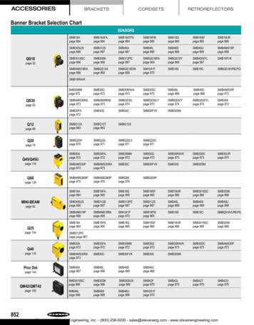
8. POSITIONING THE ELECTRODESCable length: 122 cm8.1.2.ELECTRODE PLACEMENTThis electrode configuration allows you to obtain the maximal number of independent ECGchannels with the smallest possible number of electrodes.Place the red electrode ( ) over a rib at V5, the brown electrode ( ) on the xiphoid muscle atthe bottom of the sternum and the white electrode (common – pole) on the sternum over themanubrium.Positioning of electrodes for this configuration is shown in the figure below.1328.2.TWO CHANNEL RECORDING (5 ELECTRODES)8.2.1.ELECTRODESChannel: poleCommon – poleA1: white2: redB3: black4: brownGround5: green5: greenCable length: 122 cm8.2.2.ELECTRODE PLACEMENTThe CMV5 lead ( 60 axis) detects identifiable P waves and high-amplitude QRS complexes.It is also acknowledged as being sensitive in detecting myocardial ischemia during exercisetesting. Place the white (-) electrode on the sternum, over the manubrium and the red ( )electrode over a rib at V5.The CMAVF2 lead ( 90 axis) provides high-amplitude P waves. The black electrode is alsoplaced on the manubrium as close as possible to the white electrode but not on top of it. Thebrown electrode is placed on the xiphoid muscle at the bottom of the sternum.The ground electrode is placed on a rib on the right side of the chest.Positioning of electrodes for CMV5, CMAVF2 is shown in the figure below:16SpiderView – UA10709B
8. POSITIONING THE ELECTRODES314258.3.THREE CHANNEL RECORDING (7 ELECTRODES)8.3.1.ELECTRODESChannel: poleCommon – poleA1: white2: redB3: black4: brownC5: blue6: orangeGround7: green7: greenCable length: 152 cm8.3.2.ELECTRODE PLACEMENTGenerally, it is recommended that a completely different lead be used in addition to the twoleads used for a two-channel recording. CBV2 is an anteroposterior lead close to the Z axisthat allows thorough study of changes in the ST segment related to the left coronary artery,as well as the LAD artery and circumflex artery.The blue electrode lies posteriorly and paravertebrally facing V2. The orange electrode isplaced in V2.The ground electrode is placed on a rib on the right side of the chest.31647SpiderView – UA10709B5217
8. POSITIONING THE ELECTRODES8.4.XYZ CHANNEL RECORDING (7 ELECTRODES)8.4.1.ELECTRODESThis electrode configuration is suggested for:― Derived 12 channel ambulatory recordings*.― High Resolution 20min recordings for late potential analysis; for this application ashielded cable is recommended to reduce noise level.WhiteX-Fourth intercostal space in right midaxillary lineRedX Fourth intercostal space in left midaxillary lineBlackY-Superior aspect of the manubriumBrownY Lower ribsBlueZ-Directly posterior to V2OrangeZ Standard V2 positionGreenrefOver 8th rib in right midclavicular lineCable length: 152 cm* Available with SyneScope Holter software.8.4.2.ELECTRODE PLACEMENTFor an ambulatory orthogonal ECG recording close to the XYZ late potential configuration,the following hook-up is recommended. However, due to constraints of daily activities, someminor variations may be introduced, provided that polarity of electrodes and axis orientationsare maintained.YZ Z-Xref18X Y 8.5.TWELVE-LEAD RECORDING* (10 ELECTRODES)8.5.1.ELECTRODES1YellowLALeft Anterior acromium2RedRARight Anterior acromium3GreenLLLeft Interior iliac crest10BlackGNDRight Interior iliac crest4PurpleV1V1 positionSpiderView – UA10709B
8. POSITIONING THE ELECTRODES5PurpleV2V2 position6PurpleV3V3 position7PurpleV4V4 position8PurpleV5V5 position9PurpleV6V6 positionCable length: 150 cm* Available with SyneScope Holter Software.8.5.2.ELECTRODE PLACEMENTRALAV1V2V3V4 V5GNDThis configuration is intended to provide astandard 12 lead recording similar to thatobtained from a resting ECG:―Lead I, II, III (Einthoven leads)―Leads avR, avL, avF (augmented limbleads)―Leads V1 to V6 (precordial leads)V6LLThe central terminal of Wilson is automatically calculated by SpiderView.Because of ambulatory conditions we recommend placing electrodes on the roots of the limbs(Mason-Likkar configuration), often used in exercise testing.NOTE: Due to the positioning of peripheral leads on the upper extremity of the limbs,ambulatory recordings obtained in this configuration are more likely to contain movementartifacts than other bipolar configurations previously described in this manual.SpiderView – UA10709B19
9. USING THE PROGRAMMING BUTTONS9.USING THE PROGRAMMING BUTTONS9.1.USER INTERFACE STRUCTUREThe user interface is structured as a sequence of several screens, which allow you to set theparameters of the device and of the recording. The programming keypad contains 7 buttons(the numbers refer to the “general description” section):These buttons (2) are used to move from one screen to another.These buttons (3) are used to move the cursor inside one screen and to modify the parameters of the screen.This button (4) is used for final confirmation to start a recording. During therecording it is also used as an event button by the patient.The ON/OFF button (1) is placed on the back of the device under the back cover.NOTE: The event button has a flat surface in order to avoid accidental activation of thebutton and causing false patient events in the report.After switching on the recorder and inserting a flash card, the device displays the name ofthe last patient recorded on it. Moving to the left allows access to the device’s parameters(date, time, voltage, contrast ). Moving to the right allows you to set the recording’sparameters and to begin the recording. The following chapters will explain the details aboutthe SpiderView screens.9.2.STARTING THE DEVICE9.2.1.SWITCHING ONIn order to insert the battery, please refer to section 6.2 “Opening the battery cover”.After inserting a battery and connecting the patient cable, press the On/Off button (1).20SpiderView – UA10709B
9. USING THE PROGRAMMING BUTTONSA beep indicates the start-up of the recorder. The LCD screen lights up and the deviceperforms a number of automatic tests to check that all of its components are functioningproperly and carries out various initialization procedures.If the display remains blocked on an AUTOTEST number, this indicates that a problem hasbeen detected. Contact MicroPort After-Sales Service.If all tests are normal, the message INSERT CARD is displayed.If no operations are performed within 5 minutes, SpiderView beeps and then automaticallyswitches off.9.2.2.INSERTING THE SD CARD1. Insert the card into the slot (8), as shown in the illustration, with the front of the card facingup. The card has a beveled edge in one corner, which should be at the top right-handside when inserting the card.2. Push the card completely in, in order to ensure a good connection. If the card is notcorrectly inserted, the cover of the case cannot be closed.WARNING: SpiderView has been designed to fully support flash cards with NANDtechnology. Older MMC cards with NOR technology do not guarantee optimal performanceof the device.WARNING: SpiderView is only guaranteed to work properly if flash cards supplied byMicroPort are used. If you do not use a MicroPort card, the following message will appear:“Warning: Unknown card provider”. Furthermore, a flash card designed for use inMicroPort recorders should not be used for other applications; if this does happen, theSpiderView may no longer be able to read the card.If the flash card is not blank, the name of the last patient recorded is displayed on the screen.This allows you to check the card that you are going to use to perform a new recording. Therecording on the flash card will be automatically erased by starting a new recording.Move to the next screen using the right screen button (2) to visualize the patient’s ECG.SpiderView – UA10709B21
10. STARTING THE HOLTER RECORDING10. STARTING THE HOLTER RECORDING10.1.PROGRAMMING USING THE BUTTONS10.1.1. ECG screenThis screen allows you to:―Visually check the quality of the ECG leads―Program the type of pacemaker to recordECG’s amplitude and scrolling speed can be changed for a better visualization on the screen.This will not be taken into account during the recording.For an accurate analysis of the ECG on the Holter analyzing software, the amplitude of theQRS complexes on the first two channels should be at least 1 mV. This corresponds to theamplitude of the calibration bar on the left side of the display.10.1.2. Pacemaker recordingsIf the patient undergoing a Holter recording has a pacemaker, it is mandatory to declare thepresence and type of pacemaker to ensure the ECG analysis software classifies the pacedbeats correctly.This must be done on the ECG screen: move the cursor to the field “No PM” and modify itusing the buttonsand.The device records single chamber or dual chamber pacemakers with two differentsensitivities: Unipolar (less sensitive) or Bipolar (more sensitive).22SpiderView – UA10709B
10. STARTING THE HOLTER RECORDINGNOTE: If the type of pacemaker is unknown, it is suggested to select bipolar mode.A high sensitivity mode is available. It can be used to detect very low amplitude PM spikes.Because of the high sensibility, it is likely that noise and muscular or movement artifacts aredetected as stimulation spikes. A shielded cable is suggested in order to reduce false pacingspike detections.10.1.3. Insert patient nameThe next screen allows you to enter the patient’s name onto the flash card. This is necessaryso that the Holter recording will be unequivocally associated with this patient’s name whendownloaded.10.1.4. Select recording protocol, insert patient ID and activate the accelerometer sensorIn this screen the ECG analysis protocol can be selected with or without activating theaccelerometer sensor:AdultNormal analysis protocolInfantFrom 0 to1 year (or weight 10Kg)Long QTPatients with long QT or wide T wavesAdult, Infant, Long QT AccAdult, Infant or Long QT protocol with accelerometer activatedThe protocol can be modified on the Holter software after the card has been downloaded,but if the accelerometer sensor has not been activated at the start those data cannot bedisplayed. You may also insert a patient ID number that will be downloaded together withpatient’s name.10.1.5. Select the recording modeSpiderView can work in different recording modes using di
SpiderView is not compatible with the ELATEC and SyneView analysis software systems. . SyneTec, EasyScope, SyneView2 and SyneCom. TYPE OF RECORDING SpiderView offers three types of recording: ― Holter recording only. ― High-Resolution ECG recording only. ― High-Resolution ECG recording followed by a 24-hour standard Holter recording. .