Transcription
USB InstrumentsEasyScope II for DS1M12 "Stingray"Help 2006 USB-Instruments
IEasyScope II for DS1M12 HelpTable of Contents3Part I Introduction1 Welcome to.EasyScope II for DS1M1232 EasyScope.II Features45Part II Installing EasyScope II1 Installing the.EasyScope II Software52 Installing.the USB Drivers1013Part III Using EasyScope II1 EasyScope.II Overview132 Front Panel.Functions14Run/Stop.and Single Buttons14Timebase.Settings15Input Gain.Settings16GND Reference. 18Trigger Settings. 19AC/DC Coupling. 22Invert. 23Output . 24Horizontal.Slide Bar25XY. 26FFT Display. 27FFT Overview. 27Man. 28Averaging. 29Zero Pad. 30File Menu. 32FFT Window.Menu33Spectrum.Menu34Signal . 35Meter A and.Meter B36Cursor X . 38Cursor A .and Cursor B40Auto Set . 413 Menu Functions. 42File Menu. 42Screen Menu. 43Cursors Menu. 49Samples Menu. 50Trigger Menu. 51Tools Menu. 52Help Menu. 564 Quitting EasyScope.II57 2006 USB-Instruments
ContentsPart IV AppendixII581 Error Messages. 58File Not Found. 58Failed to Configure.DS1M1259DS1M12A.B Not Found .60FT Write .- General IO Error.61FT GetQueueStatus.- General IO Error.622 Uninstalling.EasyScope II63Index 2006 USB-Instruments65
3EasyScope II for DS1M12 Help1Introduction1.1Welcome to EasyScope II for DS1M12EasyScope II is the easy to use but powerful Digital Sampling Oscilloscope application program forthe USB Instruments DS1M12 Stingray.It runs on any USB 1.1 or USB 2.0 equipped PC using Windows 98, ME, 2000 or XP. 2006 USB-Instruments
Introduction1.2EasyScope II Attractive, easy to use visual displayF.F.T. (Fast Fourier Transform) display2 oscilloscope channelsAdvanced trigger settings including edge and pulse triggeringDelayed timebase functionSignal generatorExternal triggerIntegrated digital Volt metersAuto Set functionTimebase from 2 ms/div to 50 ms/divInput ranges from 0.01 V/div to 5 V/divO.S.D. markers for voltage measurementO.S.D. markers for time / frequency measurementSave oscilloscope screens to Windows BMP filesExport 10 most recent oscilloscope traces to CSV fileScreen printout facilityAC/DC coupling supportSupport for x1 and x10 probesUser-defined oscilloscope display colour themesVariable persistence mode displayLoad and save colour themes to file 2006 USB-Instruments4
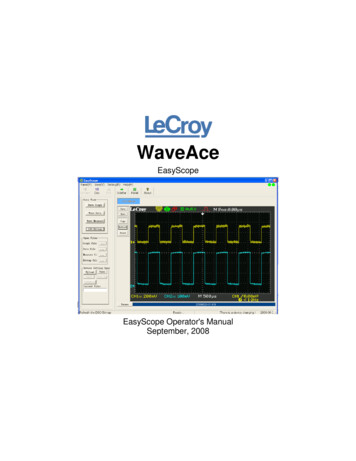
5EasyScope II for DS1M12 Help2Installing EasyScope II2.1Installing the EasyScope II SoftwareBefore connecting the instrument to the PC, insert the supplied installation disk into the CD-ROMdrive of your PC. The following menu will appear after a few seconds.Click on the "Install EasyScope" button to launch the EasyScope installation program. Thefollowing screen will appear: 2006 USB-Instruments
Installing EasyScope II6Click on the "Next" button to bring up the License Agreement Screen.If you agree with the terms and conditions of the License Agreement, check the "I agree" box and 2006 USB-Instruments
7EasyScope II for DS1M12 Helpclick on the "Next" button to continue the installation process else click on the "Exit" button. The"Next" button is disabled if you do not agree to the terms and conditions. Agreeing to the termsand clicking on the "Next" button brings up the following screen.Select the directory you wish to install the EasyScope software into. A default directory is shownon the screen. Unless you have good reason to change it we suggest you use the defaultsuggested by the installation program. Click on the "Next" button to commence copying the files tothe EasyScope program directory. 2006 USB-Instruments
Installing EasyScope II8A progress screen (shown above) will appear as the files are installed. After a few seconds youshould see the "Installation was completed successfully" message. Click on the "OK" button tocomplete the final stage of the installation process. 2006 USB-Instruments
9EasyScope II for DS1M12 HelpThe installation process is now complete. You can launch the EasyScope program from thedesktop by double-clicking on the EasyScope icon (pictured below).You can also launch the EasyScope program from the Start - Programs - EasyScope II forDS1M12 menu on the Windows Toolbar.As shown above, you also have access to the EasyScope Help files and Program Uninstaller fromthere.Before using EasyScope, the USB drivers need to be installed. This is done by plugging theinstrument into a spare USB port on the PC. The instrument should be plugged into a USB hubport of your PC or alternatively, a self-powered USB hub (one that has it's own power supply).If this is the first time that the instrument has been plugged in, Windows will then request the USBdrivers for your product. See Installing the USB Drivers for further details. 2006 USB-Instruments
Installing EasyScope II2.210Installing the USB DriversBefore using EasyScope the USB drivers need to be installed. This is done by plugging theinstrument into a spare USB port on the PC. The instrument should be plugged into a USB port onyour PC or alternatively, a self-powered USB hub (one that has it's own power supply).If this is the first time that the instrument has been plugged in, Windows will request the USBdrivers for your product and will display a Found New Hardware Wizard dialog box. The examplebelow is for Windows 2000 but the procedure is very similar for other Windows versions.Please note that the instrument uses a single USB connection but has two USB channels that thedriver will install as channel A and channel B.Connect the instrument to a spare USB port on the PC or self-powered hub. The following screenwill appear to begin guiding you through the driver installation.Click "Next" to proceed with the installation. The following screen will appear: 2006 USB-Instruments
11EasyScope II for DS1M12 HelpSelect the option box for "Search for a suitable driver for my device (recommended)" and click"Next". 2006 USB-Instruments
Installing EasyScope II12Check the box for "CD-ROM drives" and un-check all others.NOTE: If the CD is not available and the EasyScope software has already been installed, thencheck the "Specify a location" box and use the Browse button to select the "Drivers\WindowsDrivers" sub-directory of the EasyScope Program Files directory instead.Keep Clicking on "Next" until the installation is finished as per the screen below.Click "Finish" to complete the installation of the first device.If using Windows 2000, the second device will be installed automatically. For other versions ofWindows, the above process may need to be repeated to complete the instrument installation. 2006 USB-Instruments
13EasyScope II for DS1M12 Help3Using EasyScope II3.1EasyScope II OverviewThe EasyScope screen is split into several functional areas as shown in the picture below. Thesections that follow illustrate how to use the settings to control the functions of the instrument. 2006 USB-Instruments
Using EasyScope II3.2Front Panel Functions3.2.1Run/Stop and Single Buttons14On starting EasyScope, the program is in idle mode and displays two buttons on the bottom toolbarwith the captions "Single" and "Run". In order to display a trace on the oscilloscope you need toclick on either of the "Run" or "Single" buttons.On clicking the "Run" or "Single" buttons captured data will be displayed on the screen providingthat the trigger conditions are met or auto trigger is enabled and the trace display buttons areactive.The "Run" button is used to continuously capture and display data.When the "Run" button is clicked, the capture / display begins and the caption of the buttonchanges to "Stop". The "Single" button is "greyed-out" as the two functions are mutually exclusive.To stop the capture, click on the "Stop" button and the oscilloscope will change back into idlemode.The "Single" button captures one screen's worth of data then returns the program to idle mode.When the "Single" button is clicked, the instrument waits on the trigger conditions being met beforeupdating the display with a single buffer of data and the caption of the "Run" button changes to"Stop". The "Single" button is "greyed-out" as the function is currently running. If the instrumentdoes not trigger, it can be returned to idle mode by clicking the "Stop" button.The last captured data buffer will remain displayed on the screen as long as the user does notchange any of the oscilloscope settings. If desired, the screen display can be saved to a WindowsBitmap (.bmp) format file, exported to a comma separated values (.csv) file for analysis using thirdparty programs or can be printed by any printer connected to the P.C. These subjects are dealtwith in later topics.An alternative to the Run / Stop button is provided through the File Menu at the top of theapplication screen. Click on "File" to select the drop down menu shown below.Click on "Run" or "Stop" as desired. Clicking on "Exit" will quit the EasyScope application. 2006 USB-Instruments
153.2.2EasyScope II for DS1M12 HelpTimebase SettingsThe timebase settings are adjusted by clicking on the rotary switch in the Timebase Panel. Thereare 14 possible settings ranging from 2 ms/division (fastest) to 50 ms/division (slowest). Pleasenote, at the lower speed settings there will be a noticeable delay between clicking on the "Run"button and the trace appearing on the oscilloscope screen. This is because the sampling(conversion) rate is low and it takes more time to capture a buffers worth of data.The button for OverSample will become checked for timebase settings of 20ms or less whentriggering on channel A or channel B. Oversampling is disabled for Auto trigger.When oversampling is active, the display will only show the trace for the channel that is being usedas the trigger source. Oversampling can be turned off by clicking the OverSample control.The timebase setting changes the sampling rate of the oscilloscope. The sampling rate isdisplayed on the bottom right of the oscilloscope panel shown below. 2006 USB-Instruments
Using EasyScope II3.2.316Input Gain SettingsThe input gain is adjusted by clicking on the Volts/Div rotary switch on each of the channel settingscontrol panels shown below. Channels A and B have independent gain settings.There are 9 gain settings available. Please note that if a gain setting is too high for the input signal,clipping will occur. To avoid clipping, select a larger voltage scale.In addition, the settings depend on if the oscilloscope probe used is a x1 (1MW input impedance)or a x10 (10MW input impedance). If a x10 oscilloscope probe is used then enable the X10 settingby clicking on the X10 button located below the rotary switch. This will re-scale the switch anddisplay cursor settings by a factor of 10.In the picture above, the oscilloscope is setup for a x1 probe. The panel below shows theoscilloscope setup for a x10 probe.The current gain setting is also displayed on the bottom right of the oscilloscope panel alongsidethe sampling rate. The presence of "X" indicates that the X10 button is active. 2006 USB-Instruments
17EasyScope II for DS1M12 Help 2006 USB-Instruments
Using EasyScope II3.2.418GND ReferenceThe ground (0V) reference is shown by a small arrow on the left hand side of the screen. Thecolour of the arrow matches the colour of the trace display. The default colours are yellow forchannel A and magenta for channel B.To adjust the ground reference setting, use the "Gnd" buttons on each channel control panel.Each Gnd reference button will adjust the ground reference for that channel only. The Gndreference can be changed both in idle mode and in run mode. 2006 USB-Instruments
193.2.5EasyScope II for DS1M12 HelpTrigger SettingsBasic trigger settings are configured using the controls on the trigger panel.The default trigger mode is for edge triggering. Other trigger modes are explained in theTrigger Menu section.AutoAllows the scope to free-run and constantly collect data without waiting for a trigger event.ChAForces the scope to wait on a trigger event on channel A defined by the other trigger controlsbefore the display is updated.ChBForces the scope to wait on a trigger event on channel B defined by the other trigger controlsbefore the display is updated.ExtForces the scope to wait on a level sensitive external trigger event. When this option is selected,the ve/-ve button is replaced with a High/Low button (shown below).This will cause the scope to trigger when the external trigger input signal is above or below theexternal trigger level. Please note that this option uses the right hand BNC connector with thegreen LED. Setting the external trigger configures the right hand BNC connector as an input.Consequently, the signal generator output is not available when the DS1M12 is using an externaltrigger source. Selecting Ext trigger when the signal generator output is active will stop the signaloutput.The external trigger voltage must be in the range -3.5V to 3.5V.Select a rising or falling edge event to trigger on by selecting " ve" (rising edge) (A " " on thedisplay indicates ve edge triggering) 2006 USB-Instruments
Using EasyScope IIor "-ve" (falling edge) (A "-" on the display indicates -ve edge triggering). 2006 USB-Instruments20
21EasyScope II for DS1M12 HelpUse the "Trigger Level" buttons to set the desired trigger level voltage. The trigger level is shownas an arrow with a "T" to the right of the oscilloscope screen and is displayed numerically above theplot. The colour of the "T" arrow matches the colour of the trace that has been selected as thetrigger source. If Ext trigger is selected, the "T" arrow colour matches the channel A trace.When channel A is selected as the trigger source, the trigger line marker on the display is a blueline. If channel B is selected as the trigger source, the trigger line marker is red. For an externaltrigger there is no line. 2006 USB-Instruments
Using EasyScope II3.2.622AC/DC CouplingAC/DC coupling is controlled by miniature relays inside the oscilloscope. To select AC or DCcoupling click on the AC/DC selector switch on each channel control panel. This will instruct theoscilloscope to change the coupling from AC to DC or vice-versa for that channel. The currentselection is highlighted in green to the right of the switch.The above picture shows AC coupling selected. 2006 USB-Instruments
233.2.7EasyScope II for DS1M12 HelpInvertAn invert button is located on each of the channel control panels.Clicking the invert button has the effect of flipping the captured data about the ground referencevalue for that channel. 2006 USB-Instruments
Using EasyScope II3.2.824OutputThe Output button along with the Ext trigger selection controls the function of the shared BNCconnector to the right of the DS1M12 with the green LED.The output button is disabled when Ext trigger is selected as this configures the BNC connector asan input. The Output button determines whether the shared BNC connector is configured as aninput or an output.If the trigger option is not set to Ext, then the signal generator output may be used. The Outputbutton enables the signal generator output. The output is active when the blue panel is illuminated.The output waveform can be configured through the SignalGen option of the Tools menu. 2006 USB-Instruments
253.2.9EasyScope II for DS1M12 HelpHorizontal Slide BarThe horizontal slide bar beneath the plot area may be used to scroll forward and backward throughthe data buffer. The trigger point is in the middle of the buffer.To operate the slide bar, click on the slider (positioned in the centre by default) and drag it to thedesired position. The display will update as this is done. 2006 USB-Instruments
Using EasyScope II263.2.10 XYThe XY button changes the trace display from a Voltage versus time (YT) format into a XY format.Channel A is mapped to the X-axis and Channel B is mapped to the Y-axis.The XY button changes to a YT button when XY mode is active. 2006 USB-Instruments
27EasyScope II for DS1M12 Help3.2.11 FFT Display3.2.11.1 FFT OverviewA fast Fourier transform (FFT) window may be accessed by clicking the FFT Display button.The FFT window will appear and is shown below.There are two pairs of cursors which may be used to measure differences in frequency. To the topof the cursors are marker blocks 1 and 2 for each active trace on the chart. To move a cursor,place the mouse pointer over the marker block you wish to move, and holding down the left mousebutton drag the cursor to the point you wish to measure.Channels can be made active or inactive by clicking on the ChA and ChB buttons. The colouredpanel on the button is illuminated when the channel is active.The units for the vertical scale may be changed between linear and logarithmic units by clicking onthe blue area beneath the chart next to the word "Amplitude".When the zoom function is active, the scroll bar at the bottom of the plot area may be used to scanthrough the FFT data. 2006 USB-Instruments
Using EasyScope II283.2.11.2 ManClicking the "Man" button in the FFT window enables the up/down buttons and changes the buttoncaption to "Auto". This allows the vertical scale of the plot to be changed manually.Clicking on "Auto" will enable autoscaling for the vertical axis. 2006 USB-Instruments
29EasyScope II for DS1M12 Help3.2.11.3 AveragingThe averaging option may be used to help eliminate noise from measurements.The averaging options available are off, 5, 10, 20 and 50 sweeps. 2006 USB-Instruments
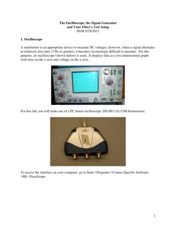
Using EasyScope II303.2.11.4 Zero PadZero padding may be used to artificially increase the number of data points included in the FFT.The default is no zero padding and using the 1024 points obtained from the data buffer. The FFTis always 1024 samples around the trigger point even if 2K, 4K or 8K buffer used.Zero padding will allow the use of either the standard 1K buffer or zero padded 2K, 4K, 8K or 16Kdata sets.Increasing the zero padding has the effect of stretching the frequency axis which will allow moreaccurate measurement with the cursors.The picture below shows the FFT of a 5V 3.472KHz square wave on channel A and a 4V 1KHzsine wave with no zero padding.The picture below shows the same input signal with x4 zero padding. The scroll bar at the bottomof the screen may be used to scroll back and forth through the data buffer. 2006 USB-Instruments
31EasyScope II for DS1M12 Help 2006 USB-Instruments
Using EasyScope II323.2.11.5 File MenuThe File menu (shown below) allows access to the two features described below:Save AsThis allows the FFT screen to be saved as a Windows Bitmap (.bmp) file. When selected, a SaveAs dialog box appears and prompts the user for a filename.PrintThe print option allows the user to send the FFT screen directly to an installed printer. 2006 USB-Instruments
33EasyScope II for DS1M12 Help3.2.11.6 FFT Window MenuThe FFT screen display can changed to use a number of different windowing algorithms. Theavailable windows are displayed when the FFT Window menu is selected (shown below).The default window is Rectangle. 2006 USB-Instruments
Using EasyScope II343.2.11.7 Spectrum MenuThe FFT screen display can be changed to use a number of different ways of scaling the Y-axisthrough the spectrum menu.The available scaling options are Power (V2), Magnitude (mV) and Phase (Rad). As indicated inthe FFT Overview section, by clicking the blue area on the axis of the FFT plot, the units can bechanged between linear and logarithmic for each of these settings.The default spectrum is Magnitude. 2006 USB-Instruments
35EasyScope II for DS1M12 Help3.2.12 SignalThe Signal button displays or clears the configuration window for the signal generator output.Please refer to the Signal Generator section in the Tools menu for more information on the signalgenerator functions. 2006 USB-Instruments
Using EasyScope II363.2.13 Meter A and Meter BThe "Meter A" and "Meter B" buttons display small panels (shown below) showing 3 measurementsof the data displayed at that time for each channel. The default measurements are mean Voltage,true RMS Voltage and frequency.The measurements displayed can be changed by clicking the Configure button at the bottom of theMeters panel which brings up the following window. 2006 USB-Instruments
37EasyScope II for DS1M12 HelpAvailable measurements are:······Mean VoltageTrue RMS VoltagePeak to Peak VoltageMinimum VoltageMaximum VoltageFrequencyThe meter functions may also be accessed through the Tools menu. 2006 USB-Instruments
Using EasyScope II383.2.14 Cursor XThe "Cursor X" button is used to enable or disable the horizontal cursors.The horizontal cursors may be used to measure the duration of a section of a waveform as shownbelow.The values of the two cursor positions are displayed at the bottom left of the plot area, along withthe difference between them. The difference has a blue background and the units may bechanged by clicking on it. If the display shows time units and the user clicks on it, the units willchange to frequency units. 2006 USB-Instruments
39EasyScope II for DS1M12 HelpSimilarly, if the display shows frequency units a click on the blue area will change the units to timeunits. 2006 USB-Instruments
Using EasyScope II403.2.15 Cursor A and Cursor BThe "Cursor A" and "Cursor B" buttons are used to enable or disable the vertical cursors.The vertical cursors can be used to measure the voltage difference between two points of a traceas shown below.The values of the cursor positions are displayed at the bottom of the plot area, along with thedifference between them. 2006 USB-Instruments
41EasyScope II for DS1M12 Help3.2.16 Auto SetClicking the "Auto Set" button will launch the auto set function. The button caption will read"Cancel" while the auto set function is running.The auto set function attempts to home in on a signal and display it clearly on the plot area byoptimising the timebase and gain settings for the detected signal. If no signal is detected, the autoset function will terminate.The auto set function may be cancelled by clicking "Cancel". 2006 USB-Instruments
Using EasyScope II3.3Menu Functions3.3.1File Menu42The File menu (shown below) allows alternative access to the Run and Stop functions (alsoaccessible through the Run/Stop button on the front panel).The Exit option allows the user to quit the application and has the same function as the WindowsClose button . 2006 USB-Instruments
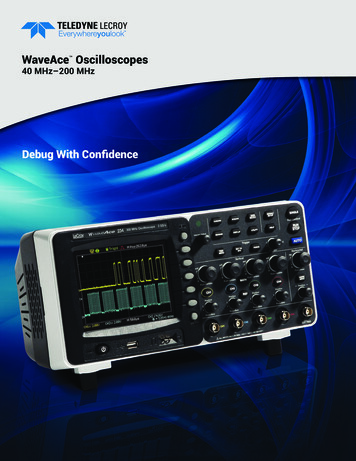
433.3.2EasyScope II for DS1M12 HelpScreen MenuThe screen menu (shown below) allows access to options for customising the appearance of theEasyScope interface and exporting data or images to files.The menu items have the following functions:IlluminateThe illuminate option controls the brightness of the grid on the scope display.With the grid illuminated, it is a bright green colour. 2006 USB-Instruments
Using EasyScope II44When the grid is not illuminated, it is a dark green. These colours are the default and may becustomised through the Screen Menu options below. 2006 USB-Instruments
45EasyScope II for DS1M12 HelpSave Screen Image to FileThis allows the plot area to be saved to a Windows Bitmap (.bmp) file. A Save As dialog boxappears and prompts the user to provide a filename for the image.Setup PrinterAllows configuration of a printer that is already installed. Options include paper
2 Installing EasyScope II 2.1Installing the EasyScope II Software Before connecting the instrument to the PC, insert the supplied installation disk into the CD-ROM drive of your PC. The following menu will appear after a few seconds. Click on the "Install EasyScope" button to launch the EasyScope installation program. The following screen will .