Transcription
CITY OF PORTLAND, MAINEDEPARTMENT OF AVIATIONAND TRANSPORTATIONVALE AIP Discretionary GrantApplication for the Installation of aGeothermal SystemRevised and Submitted: 15th April, 2010Prepared by: Roy Williams PE LEED AP
Portland International Jetport – Revised Vale Grant Application for Geothermal System 2TABLE OF CONTENTSSECTION 1: PROJECT INFORMATION . 3SECTION 2: DESCRIPTION OF PROPOSED EMISSION REDUCTION MEASURES . 4SECTION 3: EMISSION REDUCTION ESTIMATES . 8SECTION 4: CONFIRMATION THAT EMISSION REDUCTIONS MEET CAA CRITERIA .17SECTION 5: RELATIONSHIP TO STATE IMPLEMENTATION PLAN .18SECTION 6: FUNDING SOURCES .18SECTION 7: COST EFFECTIVENESS .19SECTION 8: VEHICLE COMMITMENTS .20SECTION 9: SCHEDULE .20APPENDIX A .21APPENDIX B.22APPENDIX C .23APPENDIX D .24
Portland International Jetport – Revised Vale Grant Application for Geothermal System 3Section 1: Project informationProject Title: Vale grant for the Installation of a Geothermal SystemAirport Code: PWMAirport Name: Portland International JetportKey Contacts:1.Paul H Bradbury PEPortland International JetportAirport Director1001 Westbrook StreetPortlandMaine.04102Telephone:207 756 8029Mobile:207 232 8106phb@portlandmaine.gov2.Roy S. Williams PE LEED APPortland International jetportDeputy Director of Engineering and Facilities1001 Westbrook StreetPortlandMaine.04102Telephone:207 756 8026Mobile:207 317 1648rsw@portlandmaine.gov
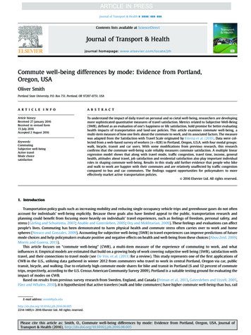
Portland International Jetport – Revised Vale Grant Application for Geothermal System 4Section 2: Description of Proposed Emission ReductionMeasuresThe Portland International Jetport is owned and operated by the City of Portland andmanaged by the City’s Department of Aviation and Transportation. The PortlandInternational Jetport is currently engaged in a major construction terminal expansion thatis scheduled to begin in April 2010. The Airport Director, Mr. Paul Bradbury and Mr.Roy Williams, the Airport Deputy Director of Engineering and Facilities, will berepresenting the City during the construction of the expansion and, if grant money isawarded, the installation and operation of the geothermal system. The ConstructionManager is Turner Construction of Boston Mass and the Architect is Gensler whoseoffice is also located in Boston Mass. The engineering designers are AMEC of Portlandand the geothermal designers are Hayley and Aldridge of Boston.The Jetport’s principal air carriers are Air Tran, Continental, Delta, JetBlue, AirWisconsin (aka United) and US Airways. Over the past year the airport has experiencedlarger than expected growth with a record passenger flows. The Portland InternationalJetport anticipates total passenger volume to continue to grow further and this growth,originating from the introduction of two new low cost airlines, has resulted in the need toexpand the Portland Jetport’s main terminal building. The existing passenger terminalbuilding will be expanded in a north westerly direction (see Appendix D site plan). Theterminal expansion is approximately 145,000 square feet and will include renovation ofportions of the existing Jetport main terminal building. Scope of work shall include arelocated employee parking area and this shall be the site of the new geothermal systembore field. Much consideration was given to the location of the geothermal bore field asthe projected life of the system is 40 years and the airports 30 year master plan showsgrowth in a westerly direction. Referring to Fig 1, it is clear that the optimal employeeparking site has no conflict within the 30 year master plan.It is confirmed that PWM is located in an area designated by the MeDEPAQ as amaintenance area for regulated pollutants and PWM is seeking AIP discretionary fundingfor the installation of a geothermal well system to reduce emitted pollutants from theplanned terminal expansion base plan heating plant. In particular, if emission of Nox(Oxides of Nitrogen) and VOCs (Volatile Organic Compounds) can be reduced oravoided by reduction or elimination of No 2 fuel oil usage for heating purposes, it isobvious that the regional air quality will benefit. PWM is proposing to reduce emissionsby producing heating from a geothermal plant with centralized heat pumps, supplementedby dual fuel (natural gas/ No 2 fuel oil) hot water boilers. The new geothermal plant willproduce both heating and cooling, but since the focus is on heating plant emissions, theplant heat pump capacity will be optimized for heating and the cooling plant will besupplemented with a centrifugal chiller. The geothermal plant shall serve only theterminal addition.
Portland International Jetport – Revised Vale Grant Application for Geothermal System 5Future Potential ExpansionsFig. 1 – 30 year Master Plan.Proposed Bore Field Site
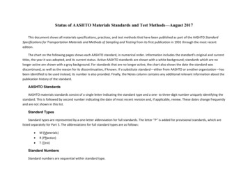
Portland International Jetport – Revised Vale Grant Application for Geothermal System 6The geothermal plant arrangement is as follows: A modular water to water heat pumpsystem located in the new terminal addition mechanical room shall generate heatingwater at 130 deg. F and chilled water at 42 deg F, depending on the season. The borefield capacity shall allow the heat pump system to produce up to 180 tons (1.6 millionBtus) of cooling and 2265 Mbtus/hr of heating or a combination of both that does notexceed an energy rate of 2265Mbtus/hr to the bore field. The heat pump system heatingand cooling source will be a bore field of multiple 400 or 500 foot deep drilled wellslocated to the north west of the terminal addition underneath a proposed employeeparking lot (see Appendix D site plan). Supply and return lines will run from a closed 2”or 3” dia. closed loop in each well to a supply manifold in an underground vault near thebore field and then run approximately 750 feet as a pair of 8” supply and return linesunderground to the terminal expansion mechanical room. See Fig. 2.Fig 2.A system pump and backup pump will circulate the heat source/heat sink loop fluid (15%propylene glycol/85% water) from the pumps in the terminal addition mechanical roomto the bore field and back. From the heat pumps, 8” pipe manifolds will connect to thechilled water piping mains and the low temperature heating water mains. A system of low
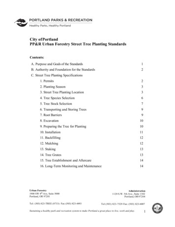
Portland International Jetport – Revised Vale Grant Application for Geothermal System 7temperature (130 deg F supply/110 deg F return) 8” heating water mains will be routed tohot water coils in Air Handling Units (AHU) 1 and 2 in the terminal addition mechanicalwell on the roof. A system pump and backup pump with variable frequency drives(VFDs) will circulate hot water through the low temperature piping mains to the lowtemperature heating equipment. A cross connection to the high temperature heating watermains will allow the hot water boilers to supplement the heat pumps during normalheating season operation and provide heating water for freeze protection if an extendedelectrical outage occurs. A system of high temperature (180 deg F supply/160 deg Freturn) 3” heating water mains will be routed to finned radiation along building perimeterwalls, the door heater and unit heaters in stairwells and baggage handling spaces. The hotwater boilers will provide hot water and each boiler will be sized to provide freezeprotection for the terminal addition. A circulator pump will be provided for each boilerand a system pump, with VFDs, will circulate hot water through high temperature pipingmains to the high temperature heating equipment.Graphic representation of a geothermal systemThe chilled water mains will serve AHUs 1 and 2 in the mechanical well on the roof, plusfan coil units and blower coils on lower levels. A 475 ton centrifugal chiller will also bepiped to the chilled water mains for supplemental cooling. A system pump and a backuppump will circulate chilled water to the heat pump, chiller and cooling equipment. A fluidcooler mounted in the terminal addition mechanical well on the roof will provide heatrejection for the chiller capacity and a condenser pump with a VFD dedicate to the chillerwill circulate water to the fluid cooler.It is important to note that the chilled water system emission reductions are zero at thePWM site as there will be no oil energy consumption conducted during this process.However, there are substantial emissions reductions back at the electricity powergenerating plant but are not valid for this grant application and therefore have not beenincluded. I have highlighted this chilled water narrative within this application to showthat there are additional environmental benefits, albeit not within the Jetport area, fromemission reductions and an electricity usage perspective but has no bearing on thisapplication.Overview of the Total Cost of ProjectA summary of hard and soft costs are shown in Table 1 below. A more detailed
Portland International Jetport – Revised Vale Grant Application for Geothermal System 8breakdown of these costs is reflected in the project application sheets in Appendix A.This summary reflects the selected bidder’s costs for construction. Appendix D includes aspreadsheet that clearly shows the bid format with the lowest bidder breakdown. It isimportant to note that as this geothermal system supplements the Terminal Expansion, anearly decision was made to “firewall” the mechanical room as the demarcation line wheregeothermal system starts and ends and no costs associated outside that firewall areincluded in this grant application other than the supply and return lines and bore field.Overview of Project CostsDescriptionProject TotalCost89%Eligible11%IneligibleAIP @95%FundingState andLocal ShareInstallation 2,791,191 2,484,160 307,031 2,359,952 431,239Design Costs 204,396 181,912 22,484 172,817 31,579AdministrationExpense 2,000 1,780 220 1,691 309Total 2,997,587 2,667,852 329,735 2,534,460 463,127Table 1 Local matching funds are provided from PWM cash reserves.This application is requesting 2,534,460 for the geothermal project. As the VALEEDMS reports indicate, this project is estimated to save a total emissions reduction of 41tons of NOx and 43 tons of Ozone over the 40 year life span of the geothermal system(See Section 3). This would equal to over 101,912 gallons of oil saved per year and aprojected savings of over 4 million gallons of heating oil over the life of the system (SeeSavings and Pollutant reductions Sheet in Appendix B).To summarize, this geothermal project application is proposed as an effort to reduceemissions by using substantially less fuel oil consumption during the heating seasonusing a ground source geothermal energy system taking advantage of the earth’s stabletemperature underground, providing heat energy in the winter and a bonus of a heat sinkin the summer.Section 3: Emission Reduction EstimatesThe EDMS ApproachThis following documents the rationale in deducing the on-site emissions reductions fromthe Jetport boiler plants by reducing the boiler plant fuel oil consumption using theVALE EDMS reporting software.
Portland International Jetport – Revised Vale Grant Application for Geothermal System 9A description of the existing and new terminal area heating plants follows:Existing Terminal Boiler PlantsThe existing 157,300 square foot Terminal space is served from two Boiler Plants in theEast and West Wing Mechanical Penthouses. Each mechanical penthouse has two hotwater boilers and each boiler is a maximum of 3 million Btuh input. The boilers in theEast Penthouse Mechanical Room have dual-fuel capability and have both gas and oilsupplies. The West Penthouse Mechanical Room boilers have only a fuel oil supply. Theboilers generate hot water for air handling unit heating coils, unit heaters, finned radiationalong the walls, radiant floor tubing and snow melt tubing buried in slabs outdoors.New Expansion Boiler PlantThe proposed terminal expansion encloses an area of approximately 140,000 sf. Almostall of this space is provided with comfort heating to comply with ASHRAE Standard 55Thermal Environmental Conditions for Human Occupancy. The proposed heating systemis a hydronic system with hot water generated by oil-fired boilers circulated to AirHandling Unit heating coils, Variable Air Volume (VAV) box heating coils, unit heaters,radiant floors, snow melting systems and finned radiation along perimeter walls. TheBoilers will generate hot water at temperatures up to 180 degrees F. The hottest waterwill be circulated to the Air Handler Units heating coils, VAV box heating coils forventilation air and building heating; and to unit heaters and finned radiation for buildingheating. Lower temperature (below 120 degrees F) water will be circulated to tubingembedded in the floor slabs for building heating and to snow melt tubing buried outside.Method of Estimating Emitted Pollutants and Pollutant ReductionIt is PWM’s understanding that the basis of the VALE grant is to reduce the amount ofoxides of nitrogen (Nox) emissions by use of a geothermal heat pump system to eliminatethe firing of distillate (No. 2 fuel) oil. To make this determination, the following steps areneeded:1. Configure the Terminal addition heating systems as oil-fired boilers (Baseconfiguration) and a Geothermal alternate with supplemental gas-fired boilers.(GSHP configuration).2. Model the new terminal building, including location, floor areas, wall areas, glassareas, and roof areas. Input the thermal performance characteristics of the buildingcomponents.3. Generate and input building use schedules including lighting, people and ventilation.4. Calculate the heating and cooling loads.5. Generate the projected energy use for the addition in terms of heating fuel energyused annually.
Portland International Jetport – Revised Vale Grant Application for Geothermal System106. Determine the Jetport as a major or minor emissions source and determine therequired Best Available Control Technology (BACT).7. Tabulate the heating fuel usage and convert to the energy units required by theemissions software. No. 2 fuel oil heat content is figured at 140,000 btu/gallon.8. Model the heating plant emissions using EDMS (Emissions and Dispersion ModelingSystem) software from the Federal Aviation Administration Office of Environmentand Energy. Compare the NOx emissions from the Base configuration and GSHPconfiguration to generate annual tons of NOX reduced by means of the GSHPsystem.Step 1: The heating systems were configured as follows: The Base configuration was aplant of two hot water boilers fired with 0.5% sulfur distillate fuel oil. The hotwater would be generated at temperatures up to 180 deg F and circulated toheating coils and finned radiation. The hot water would be mixed with coolerwater for delivery to radiant floor and snow melt systems.The GSHP configuration is a geothermal bore field of 500 foot /- drilled wellscirculating water to water–to-water heat pumps in the new ExpansionMechanical Room. The bore field will be used as a heat source for the heatpumps. Heating water will be generated by the heat pumps at temperatures up to120 deg F and circulated to radiant floors and snow melt systems. Heating coilsfor air handlers and fan coils are would be sized to provide adequate heat usinglower temperature water from the heat pump system. A gas-fired condensingboiler plant would provide hot water for the unit heaters, the finned radiationalong the exterior walls, and the domestic hot water system; heat pumps fordomestic water heating will also be investigated. The hydronic heating systempiping would be reconfigured with high-temperature and low temperature loopsto the heating equipment.Step 2: The terminal addition was modeled with Trace 700 load modeling software fromthe Trane Company. A copy of selected output reports is included in AppendixB. In the interest of providing the most accurate output, the systems weremodeled with and without domestic water heating load and the results havebeen tabulated below. The net result of the domestic water load was an increaseof 3% in fuel use.Step 3:Schedules were generated for the lights, people and ventilation. These schedulesare tabulated as percentages of the full occupancy and are shown in AppendixD. Two basic schedules; Ticketing and hold room, were generated and theoccupied spaces were classified as one or the other. The projected totaloccupancy load was tabulated from the Architectural documents; a tabulationsheet with comments is included in the Appendix B.Step 4:The Jetport heating and cooling loads were generated. Copies of the BaseConfiguration loads are included in the Appendix B. The total heating load was5900 Mbtuh and the total cooling load was 639 tons.
Portland International Jetport – Revised Vale Grant Application for Geothermal System11Step 5: The heating energy use was modeled for the Base configuration and GSHPconfiguration and the results are tabulated below.JetportExpansionOil Fired BoilerPlant NoDomestic HotWaterOil Fired BoilerPlant DomesticHot WaterThousands ofBtu/yearGallons of No. 2 FuelOil/yearKiloliters of No. 2 Fuel 7.88Table 2 The Trace Energy Consumption Summary is included in the Appendix DStep 6: Determination of Best Available Control TechnologyThe calculated boiler plant capacity has been projected at 6 million Btuh to meetthe design heating load. As noted above, the existing boiler plants have aninstalled capacity of 12 million Btuh; hence the Jetport total heating plant capacityis 18 million Btuh which would seem to put the Jetport into the Minor Sourcecategory as defined by the State of Maine Department of EnvironmentalProtection Chapter 115: Major and Minor Source Air Emission LicenseRegulations. To corroborate this determination, a calculation for the Jetport plantemissions based on 2% sulfur No. 2 fuel oil and an annual projected fuel use peryear was made. (No 2 fuel oil with a sulfur content of 2% or less is allowed byState of Maine Department of Environmental Protection Chapter 106 LOWSULFUR FUEL). According to the Jetport current air emission license, (See copyof page in Appendix B) the average annual boiler plant permitted fuel use is98,000 gallons of No. 2 fuel oil per year. Assuming a domestic hot water load of100Mbtuh during occupied periods, the building model projected a fuel use of131,525 gallons of No. 2 fuel oil per year for the Terminal Expansion. The totalfuel oil consumption for the existing and new boiler plants is estimated at 229,525gallons per year.According to the emissions factors contained in the US EPA Standard AP-42COMPILATION OF AIR POLLUTANT EMISSION FACTORS Volume I:STATIONARY POINT AND AREA SOURCES, the following quantities ofpollutants would be emitted during one year of plant operation, assuming 229,525gallons of No. 2 fuel oil are burned: (See Table 1.3-1. in Appendix B)CRITERIA POLLUTANTSO2: 32.59 tons per yearS03:0.46 tons per yearNOx: 2.30 tons per yearCO:0.57 tons per yearPM:0.23 tons per yearTHRESHOLD FOR A MAJOR SOURCE100 tons per year per Maine DEP standards100 tons per year per Maine DEP standards100 tons per year per Maine DEP standards100 tons per year per Maine DEP standards100 tons per year per Maine DEP standards
Portland International Jetport – Revised Vale Grant Application for Geothermal System12Table 3Hence, it is clear the boiler plants fall under the Minor Source definition of theState of Maine Department of Environmental Protection Chapter 115 regulations.This is a minor source with small boilers.Since it is a minor source and the boilers are small and simple commercial typesrather than large industrial or power boiler types with more sophisticated controlsystems, the Best Available Control Technology (BACT) for such plants has beenconsidered to be the firing of low-sulfur (0.5% sulfur) fuel oil rather than moreelaborate technology such as scrubbers. Recent Maine DEP license applicationsreviews have accepted low sulfur fuel with material specifications that complywith ASTM D396-78 Standard Specifications for Fuel Oil. Low sulfur No. 2 FuelOil is hereby presented as BACT for the new boiler plant.Step 7: The heating energy baselines used for the emissions modeling is shown in table 4.Jetport Expansion Only131,525 Gallons of No. 2 Fuel Oil/year497.88 Kiloliters of No. 2 Fuel Oil/yearOil Fired Boiler Plant – With Domestic Hot WaterTable 4Step 8: Eliminating the concept to have the geothermal system supplement the existingterminal due to high upfront costs, the emission reductions for the new plantusing a geothermal system was modeled using the EDMS software. The resultsare tabulated below:Jetport Addition aloneTons /yearBaseline Boiler plant1.285Geothermal and Boiler Plant0.263Reduction in tons of NOx-1.02Reduction in tons of VOC-0.055Total reduction in tons ofOzone-1.075Table 5 The Emission Reduction Reports are included in the Appendix A
Portland International Jetport – Revised Vale Grant Application for Geothermal System13Geothermal Program Optimization Field Study ComparisonA Geothermal Program Optimization Field Study Comparison analysis has beenconducted to find the most cost effective geothermal program size, designed to maximizebenefits, maximizing reductions of up front capital costs. This study was conducted as asecondary source of data to compare the EDMS software emission reductions, confirmingviability of this proposed geothermal system.The Terminal Expansion Project currently includes conventional heating and coolingsystems which can be used to assist a geothermal system. This allowed a geothermalprogram field study to be developed which captured the base load, not the peak loads,which is far more cost effective than an “all geothermal” system. Various geothermalscenarios were developed, ranging from designs providing 10% of the annual heating toload up to 100% of the annual heating load. Firstly, geothermal designs for both the“terminal expansion only” and the “expansion and existing terminal” were evaluated. Thescenarios that were investigated targeted the effect on the value proposition for capturingmore/less heating loads, to reduce fuel oil consumption and limit the amount of VALEgrant funding that would be potentially available. Each design also opportunistically usesthe geothermal system to provide some of the building cooling loads to obtain additionalenergy reduction benefits and to maintain long term well field temperature balance. Foreach scenario, the number of wells and the size of the VALE grant funding wasestimated, based on the estimated NOx and VOC reduction provided by the system. Afterreviewing the preliminary results, the design team quickly concluded that the geothermaldesigns for the “expansion and including the existing terminal building” scenariorequired too much up front capital costs and would not be feasible. Therefore, therecommendation moving forward was to design for the new terminal expansion only.After investigating a range of geothermal system sizes, it was determined that ageothermal system that provided between 75% and 95% of the annual building heatingload yielded the optimal combination of delivered long term benefit and least net cost,considering Vale grant funding. Larger geothermal systems ( 95% of the annual heatingload) were found to have increasing high up front capital costs, compared to theincremental benefit delivered. Similarly, the opportunity to maximize emissionreductions became diminished for systems smaller than ones that provide 75% of theannual heating load. On this basis geothermal design of 95% annual heating load and75% annual heating load were further developed as Scenarios A and B respectively.These will be described in more following detail. In order to “ground truth” theoptimization analysis, the field study was conducted. This program consisted of drilling asingle, 400ft deep pilot test well within the proposed limits of the well field and wasconducted to Provide data for contractor pricingAllow a thermal load test to be conducted on site, to obtain site specificparameters for designServe as a production geothermal well such that these “up front” costs would notbe lost if the project moved forward.
Portland International Jetport – Revised Vale Grant Application for Geothermal System14The thermal load test provided the following results.Thermal Load Test ResultsMeasured Ambient Ground Temperatures – F49.5EstimatedThermal(BTU/hr*ft* F)2.17ConductivityEstimated Thermal Diffusivity (ft²/day)1.37Table 6 Details of well installation, the thermal load test and the log for GTW-101are not included inAppendix D but can be provided on requestCombining the results of the optimization work together with the validated groundcharacteristics from the field test program, the following scenarios are recommended. Scenario A: 95% of low temperature base load heating and opportunistic coolingfor the new addition only. This geothermal system would require 60,000 linearfeet of geothermal well Scenario B: 75% of low temperature base load heating and opportunistic coolingfor the new addition only. This geothermal system would require 44,000 linearfeet of geothermal well.Given the available bore field space restrictions and other issues, it was recommendedthat each geothermal well be installed to depths of between 400 and 500feet below gradesurface. Accordingly, the above scenarios would yield:Number of wells per ScenarioWell depth400ft500ftScenario ScenarioAB15011012088Table 7The above program recommendations are based on the following: Multistack MS5oZ644 heat pumps15% propylene glycol antifreezeSupply temperatures delivered from the field range from 40 F and 90 FChilled water supply of 44 FHot water supply temperature of 130 F20ft center to center well spacing
Portland International Jetport – Revised Vale Grant Application for Geothermal System15 1.25” diameter HDPE U tube1.0 Btu/hr/ft- F thermal conductivity groutGeo-clips spaced on 10ft centersWells with a 6” drilled borehole diameter.Both systems will require assistance from the conventional systems. Generally, thegeothermal system is designed to provide base load heating and cooling to the plannedaddition. The following supplemental heating and cooling assistance will be required tocover the balance of the heating and cooling loads not covered by the geothermal system.Table 8 Supplemental heating and Cooling RequiredAnnualPeakScenarioHeating (MBtu)Cooling (MBtu)Heating (MBtu)Cooling 9392,5386,374System benefits include reduced NOx and VOCs reductions. See table 9 belowTable 9 - Field determined Predicted Annual Ozone Emissions Reductions byScenarioScenarioABNOx and VOC(ton/yr)0.830.66It is clear that Scenario A captures the most benefit. As outlined in Table 7, either optionof 150 wells at 400 ft depth or 120 wells of 500 ft depth or any number in between thosedepths that would yield the required 60,000 lineal feet of well bores maximizing thermaltransfer.
Portland International Jetport – Revised Vale Grant Application for Geothermal System16Conclusions:The total emission reductions estimated for the 40 year life cycle of the project, issummarized in table 10 below. If a comparison is studied between the EDMS annualreductions of 1.02 tons/year for NOx and 0.055 tons per year for VOCs this would yield atotal of 1.075 tons per year of Ozone reductions. The field study ozone reductions using adifferent modeling system has ozone reductions of 0.83 (see table 9) tons per year. This isconsidered an acceptable range of disparity and concludes that the EDMS softwarepredicted quantity of ozone reduction is reliable and will be used in this application.EDMS Total Emission ReductionsAnnual CycleCO(tons)VOC(tons)NOx(tons)Sox(tons)PṂ̣10 042Total Emission Reductions for Installation of Geothermal System40 Year Life Cycle (EDMS)CO(tons)VOC(tons)NOx(tons)Sox(tons)PṂ̣10 ̣(tons)PM25(tons)-10.204-2.208- 40.818-14.711- 2.194-1.686Table 10Summary:PWM is confident in stating that this proposed system can significantly reduce the carbonfootprint of the new expansion by utilizing an on-site source of clean, renewable energywhich falls in line with the VALE mission statement “VALE is a national program toreduce airport ground emissions at commercial service airports located in designated airquality nonattainment and maintenance areas. The program was established to financelow emission vehicles, refueling and recharging stations, gate electrification, and otherairport air quality improvements”.
Portland International Jetport – Revised Vale Grant Application for Geothermal System17Section 4: Confirmation that Emission Reductions meet CAACriteria4.1 Quantifiable:The emission reductions have been determined by using the EDMS software version5.1.2. In addition to the EDMS modeling software, a PWM funded field study wasperformed (as described in section 3) to compare predicted emission r
by dual fuel (natural gas/ No 2 fuel oil) hot water boilers. The new geothermal plant will produce both heating and cooling, but since the focus is on heating plant emissions, the plant heat pump capacity will be optimized for heating and the cooling plant will be supplemented with a centrifugal chiller. The geothermal plant shall serve only the