Transcription
Operating InstructionsHERMA 400
PREFACEOperating Instructions HERMA 400PrefaceThese operating instructions are to help you to safely set up your machine and operate it troublefree.You should read all of these instructions before starting the machine in order to get well acquaintedwith it.We made an effort to describe all important points clearly and unambiguously.However, if you have any queries or suggestions for the development of these instructions pleasecontact us.HERMA GmbH, Technical DocumentationExplanation of symbols!DANGER: Indicates a potentially hazardous situation which, if not avoided,will result in death or serious injury.!CAUTION: Indicates a potentially hazardous situation which, if notavoided, will result in minor or moderate injury and physical damage.!Indicates that the operation must be performed without fail / theinformation is mandatory to take notice of.Indicates that the operation is prohibitediIndicates information you should take notice of.NoteContents subject to modifications.No part of this documentation may be reproduced or processed, copied, or distributed with the help ofelectronic systems in any form without prior written permission of HERMA GmbHVersion 3.15 GB/US (150708)2008 Copyright HERMA GmbH2
Operating Instructions HERMA 400CONVENTIONSConventionsElements of the H400 control are designated and depicted in these instructions as follows:Switch-on keyManual feed keyFunction keyLED (on)LED (blinks)LED (off)Minus keyPlus keyEnter keyFind further explanation on these elements in section 5.1.1.b3
CONVENTIONSOperating Instructions HERMA 400Labelling Systemswww.herma.com4mail@herma.de
Operating Instructions HERMA 400TABLE OF CONTENTSTable of 5.55.5.15.5.25.5.35.5.3.1Safety 9Important Safety Precautions 9Safety notes 11Transport, Installation and Connection 13Transporting the machine 13Installing the machine 13Electrical connection / Power supply 14Connections 14Operational range 15Proper use of the machine 15Adhesive labels 15Threading the Label Web 17Label web insertion schemes 17Right-hand applicator with standard dispensing plate 17Left-hand applicator with standard dispensing plate 17Right-hand applicator with pivot beak 18Left-hand applicator with pivot beak 18Detailed illustrations 18Right-hand applicator with dispensing plate with spring-loaded roller, 75 angular 19Left-hand applicator with dispensing plate with spring-loaded roller, 75 angular 19Winder system, left-hand applicator 20Winder system, right-hand applicator 21Putting into Operation and Operation 23Operation / Settings via the H400 control 24Design 25Key pad 25Display 27Function diagram 27End of reel and diminishing reel (internal) 28Overview display structure HERMA 400 29The display’s Quick Menu 30Start delay applicator (Quick Menu parameter) 31Stop delay label (Quick Menu parameter) 31Speed of the applicator (Quick Menu parameter) 32Speed of the product (Quick Menu parameter, optional) 32Potentiometers 32The display’s configuration menu 33Calling up 33Design 33Menu 100 Basic data 33120 Master encoder Pulses / revolution 335
TABLE OF .26.2.16Operating Instructions HERMA 400121 Master encoder Distance / revolution 34122 Master encoder Start compensation 34123 Master encoder Stop compensation 34124 Master encoder Mini loop on/off 34125 Master encoder Mini loop start delay 34126 Master encoder Mini loop size 34115 Master enc. transfer 34116 Master enc. transfer Label pos. difference 35117 Masterenc. transfer Start compensation 35140 Start signal 35141 Mark field 1 35142 Mark field 2 35143 Mark field 3 35144 Start inhibit distance 35160 Multi labelling 36161 Multi labelling Number of labels 36130 Stop signal 36131 Mark field 1 36132 Mark field 2 36133 Mark field 3 36134 Stop inhibit distance 37135 Hole inhibit distance 37190 Printer on/off 37194 Printer Start delay 37195 Printer Print time 37196 Stop at missing label 37Menu 200 Transfer data 38210 Pivot beak on/off 38211 Pivot beak Type 38212 Pivot beak Start delay 39213 Pivot beak Activation time 39214 Pivot beak Stop delay 39225 Moving beak Label start delay 39227 Moving beak Work pos. return del. 39229 Moving beak Home pos. reached 39236 Transfer unit Work pos. reached 40237 Transfer unit Work pos. return del. 40238 Transfer unit Blow 40239 Transfer unit Home pos. reached 40239 Transfer unit After blow 40280 Label check on / off 40284 Label check aft. feed 40285 Lab. check aft. transf. 40286 Label check start delay 41Menu 400 Formats 41Menu 500 Counters 41Menu 900 System 41910 Rotate display 41911 Contrast 41912 Sprache / Language 41950 Bus address (RS485) 41952 Display add. output 41Overview and sub-assemblies 43Overview 43Function 43Sub-assemblies 44Standard unwinder 45
Operating Instructions HERMA 1.337.1.1.347.1.1.357.1.27.1.2.17.1.3Motorized unwinder 49Loop-type unwinder 51Label web brake 54Label sensor FS01 56Label sensor optoelectronic 58Dispensing systems 60Rigid/Straight dispensing plates 60Dispensing plate, 15 angular 61Pivot beak / Application unit 62Moving beak 63Transfer systems 64Telescope 64Drive/Transport roller 65Backing paper take-up unit standard 66Backing paper take-up unit motorized 71Troubleshooting 73Indication of malfunctions 73List of malfunctions (indicated via display) 74SM107 End of label web 74SM108 Dispensing beak does not reach home position 74SM109 Dispensing beak does not leave home position 74SM110 Dispensing beak does not reach work position 74SM111 Dispensing beak does not leave work position 74SM113 Transfer unit does not reach home position 74SM114 Transfer unit does not leave home position 74SM115 Transfer unit does not reach work position 75SM116 Transfer unit does not leave work position 75SM119 Label check Error after label feed 75SM120 Label check Error after label transfer 75SM148 Missing label series fault (web break?) 75SM153 Multi labelling Start sequence too close 75SM164 Start signal Sensor mark not detected 75SM165 Roller unit Communication error 75SM166 Applicator Communication error 75SM167 Roller unit Error 75SM168 CAN connection Disconnect! 76SM169 Firmware update required! 76SM181 Chip changed! 76SM199 CAN communication no CAN module detected 76SM910 Drive failure Low voltage 76SM911 Drive failure High voltage 76SM912 Drive failure High temperature 76SM913 Drive failure Overload (period) 76SM914 Drive failure 76SM917 Drive failure Powerfail 76SM918 Drive failure 76SM919 Drive failure Low voltage (peak) 76SM920 Drive failure Overload (peak) 77SM921 Drive failure 77SM922 Drive failure 77SM923 Drive failure 77SM924 Drive failure Overload 77SM925 CAN communication disturbed 77Malfunction table (LED indication) 78Remedy of malfunctions 79Error blink codes with PLC connection 797
Operating Instructions HERMA 4007.27.37.3.17.3.27.3.37.4Other malfunctions 80Replace the drive unit 82Remove the drive unit 82Ship the drive unit 84Mount the drive unit 84Technical Service 848Cleaning and maintenance 859Technical Data 879.19.2Inputs / outputs (X10) (option, standard signals) 89Inputs / outputs (X19) (option, extended signals) 9010Declaration of Conformity / Manufacturer 9111Spare parts 93Index 1058
1SafetyThis machine complies with the essential safety and health requirements of the Machinery Directive98/37/EC.1.1Important Safety PrecautionsDANGERUse HERMA 400 applicators onTN mains networks only.!Failure to observe this instruction couldresult in electric shocks, injuries and/orfire.Before working on parts of theelectrical equipmentdisconnect the machine frommains.!Failure to observe this instruction couldresult in electric shocks and injuries.Install machine to aprofessionally installed andearthed socket.!Failure to observe this instruction couldresult in electric shocks, injuries and/orfire.Wait for at least five minutesbefore opening the housing ortouching connector pins whencutting the applicator off mains.!Failure to observe this instruction couldresult in electric shocks and injuries.Do not expose the cables tosharp edges, excessivepressing forces, heavyloads or pinching forces.Install an external emergencystop device so that you canshut off power in anyemergency cases.Failure to observe this instruction couldresult in electric shocks, malfunction and/ordamages.Failure to observe this instruction couldresult in injuries, electric shocks, fire,malfunction and/or mechanicaldamages!!Read before use!9
1SAFETYOperating Instructions HERMA 400Important Safety Precautions (cont.)CAUTIONIf an error occurs, remove thecauses for the error andsecure the safety beforerestarting the operation.Avoid extreme adjustment orchange. Avoid an operationwhich causes unstable action.Failure to observe this instruction couldresult in injuries.Failure to observe this instruction couldresult in injuries.!Do not modify or repair thedrive unit.Failure to observe this instruction couldresult in fire, electric shocks and/orinjuries.Observe the voltagespecified.!Failure to observe this instruction couldresult in electric shocks, injuries and/orfire.Screw on all plugs completely.Make sure contact is reliableand lasting.Do not reach into the areawhere the feed roller drawsin the web when machine ison.Failure to observe this instruction couldresult in electric shocks and injuries.Failure to observe this instruction couldresult in injuries.!Read before use!10
1SAFETYOperating Instructions HERMA 4001.2!Safety notesPay attention to the following basic safety notes: Check operatability of protective equipment before setting into operation for the first time. Check operatability of protective equipment each time before setting to work. Non-operational protective equipment has to be replaced or repaired immediately. Technical status of protective equipment has to be inspected by competent staff on a regularbasis, at least once a year. If safe operation of the machine can no longer be guaranteed it has to be put out of actionimmediately and be secured against further use. Machine may be operated by trained staff only.Carry out supplementary training. Give instructions for safe operation. Process only products that are suitable for the machine. Safety switches must not be bypassed. The method of cleaning given in this manual must be observed. Use original spare parts and accessories only. Machine must not be modified. Carefully store these operating instructions.On reselling the machine this manual must be passed on to the new owner.!Attention: The user is solely responsible for injuries or damage caused by improper use that isnot in accordance with the instructions in this manual.Read before use!11
1SAFETYOperating Instructions HERMA 400Labelling Systemswww.herma.com12mail@herma.de
2Transport, Installation and Connection2.1Transporting the machineWhen transporting the machine with the help of a fork lifter/lift-truck observe the following:! Means of transport has to be approved for machine weight. Safety regulations for transporting and lifting of weights must be observed. The forks must be passed through between machine feet. Pay attention to the center of gravityof the machine. The forks must jut out from the opposite side of the machine.2.2Installing the machineIf you should notice damage due to transport when you unpack the machine inform your HERMA salesoffice immediately.! ATTENTION: USE THE MACHINE IN DRY ROOMS. Machine has to be installed such that it is stable and secure.WARRANTYiImportant: Opening the screws at the front of the drive unit will void the warranty!13
2TRANSPORT, INSTALLATION AND CONNECTION2.3Operating Instructions HERMA 400Electrical connection / Power supply!! HERMA 400 applicators must be used on TN mains networks only. Connect the machine to AC mains only and verify whether your line voltage meets the voltagegiven on the type plate. The machine must be connected to a professionally installed and earthed socket or must beprofessionally connected in the control box of the corresponding machine. Work on electrical components may only be carried out by an authorized person observing therelevant safety regulations. Before working on parts of the electrical equipment disconnect the machine from mains! When cutting the HERMA 400 applicator off mains you must wait for at least five minutes beforeopening the housing or touching connector pins. RESIDUAL VOLTAGES!2.3.1ConnectionsThe following connections are available at the HERMA 400 applicator (depending on the configuration):X14 () /(X16 (special)*)X16 (X19 (,X10 (,,,,,X13 (all types))/,,)**X11 (,,))X15X12X17Shown here: left-hand appl.;Right-hand appl.: mirror img.X14 – Serial OUTX16 – Labelling startX19 – Inputs/Outputs (ext. signals)X10 – Inputs/Outputs (stand. signals) /signal column (optional)X12 – Power supplyiX13 – Serial INX11 – Master encoder*X16 as special case, if X10/X19 occupied and separate start signal required .Impossible with.**X16 as start signal, if X10/X19 are free.All plugs are secured with coupling rings.Do not chock coupling ring when screwing it onto socket, as the thread may be damaged orrendered unusable. Screw on completely to make sure contact is reliable and lasting.See chapter 9 for the assignment of connectors X10 and X19 (if available).14X17 – Pivot beak/PrinterX15 – Label sensor
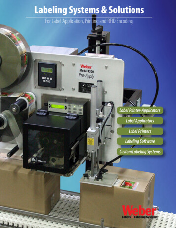
3Operational range3.1Proper use of the machineYour labeller HERMA 400 is an electronically driven machine suitable for labelling various productswith different types of adhesive labels.With this applicator you can unwind label reels and rewind the backing paper.If required the labeller can be equipped with a printing unit so that you can print on your label e.g. linesof text, varying data, bar codes, and batch numbers.Other purposes than those described above, especially winding other material than label reels, are notintended and are prohibited.3.2Adhesive labelsWinding outside1324Winding inside1234Label reelReel coreLabelBacking paper3 4 Label web123415
3OPERATIONAL RANGEOperating Instructions HERMA 400Labelling Systemswww.herma.com16mail@herma.de
4Threading the Label Web4.1Label web insertion schemesThe following schemes show how to insert the label web with the most common standard applicators.A separate insertion scheme is provided for applicator configurations other than shown here . As thecase may be, this scheme may also be attached to the machine.!4.1.1Caution:Before threading the label web make sure the applicator / machine is switched off.Right-hand applicator with standard dispensing plate681297O Außenwicklung / outside windingI Innenwicklung / inside windingO4.1.2ILeft-hand applicator with standard dispensing plate681296O Außenwicklung / outside windingI Innenwicklung / inside windingIO17
4THREADING THE LABEL WEB4.1.3Operating Instructions HERMA 400Right-hand applicator with pivot beak681299O Außenwicklung / outside windingI Innenwicklung / inside windingIO4.1.4Left-hand applicator with pivot beak681298O Außenwicklung / outside windingI Innenwicklung / inside windingI4.1.4.1ODetailed illustrationsDetail dispensing plateDetail pivot beakDetail dispensing plate, 75 angular18
4THREADING THE LABEL WEBOperating Instructions HERMA 4004.1.5Right-hand applicator with dispensing plate with spring-loaded roller, 75 angularIO681300O Außenwicklung / outside windingI Innenwicklung / inside winding4.1.6Left-hand applicator with dispensing plate with spring-loaded roller, 75 angularIO681301O Außenwicklung / outside windingI Innenwicklung / inside windingFurther to these standard layouts there are seven variants each when using the winder system(motorized unwinder and rewinder, with or without loop-type unwinder), the arrangements of whichincluding web path is shown in the following illustrations.19
4THREADING THE LABEL WEB4.1.7Operating Instructions HERMA 400Winder system, left-hand applicator*L1L2L3L4L5L6L7* The winder system is a moduar system consisting of the individual components of unwinder, looptype unwinder and backing paper take up unit (rewinder), each of which is motor driven . See sections6.2.2, 6.2.3 and 6.2.11.20
4THREADING THE LABEL WEBOperating Instructions HERMA 4004.1.8Winder system, right-hand applicatorR1R2R3R4R5R6R721
4THREADING THE LABEL WEBOperating Instructions HERMA 400Labelling Systemswww.herma.com22mail@herma.de
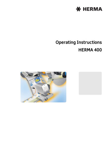
5Putting into Operation and OperationiLabellers which are part of a larger machine structure are usually switched on with the main switchfor the entire setup (see also separate manual).Single labellers are put into operation as shown here. Connect power plug with mains.1! Press switch-on key 1 at the applicator.The machine is ready to operate.2Pressing button 2 will dispense a label.3Pressing button 3 twice (quickly) will activate or deactivate theoptional printer. For more functions of this key see section 5.1.1.1on page 25.Important: When inserting a new label reel always dispense at least two labels manually with thehelp of the key !This will teach in the label length / max. label cycle.23
5PUTTING INTO OPERATION AND OPERATION5.1Operating Instructions HERMA 400Operation / Settings via the H400 controlCONVENTIONSElements of the H400 control are designated and depicted in this chapter as follows:Switch-on keyManual feed keyFunction keyLED (on)LED (blinks)LED (off)Minus keyPlus keyEnter keyFind further explanation on these elements in section 5.1.1.24
5PUTTING INTO OPERATION AND OPERATIONOperating Instructions HERMA 4005.1.1DesignApplicators HERMA 400 are operated via the keys of the key pad and the display. The display allowsentry and adjustment of applicator parameters. Basic values, such as e.g. the start delay of theapplicator, may be set either here or as well via optional potentiometers (in an external housing or inthe control box).Key pad5.1.1.1DisplayKey padKeys of the key pad have the following function (provided the applictor is not connected to a PLC; inthat case the functions of the keys may be disabled. See the respective remark.):Applicator ON/OFFThe LED of the key is on if the drive is ON.(Function available if not jumper „Remote“ is set on X27. In that case switching on/off wouldbe effected via pin X10.6)Manual feedingYou can manually feed a label by pressing this key.Important: When inserting a new label reel always dispense at least twolabels manually with the help of the key!(Function available if jumper „Feed“ is set on X27. If the jumper is not set feeding can beeffected via external signal only)Function keyThere are several functions for this key (see following table).25
5PUTTING INTO OPERATION AND OPERATIONOperating Instructions HERMA 400(2x)Printer ON/OFFAn optional printer can be switched on and off with the function key,pressing it quickly two times („double tip“).If the printer is ON the function „compensate for missing labels“ isactive at the same time. That means, missing labels on the web will bedetected automatically and the web always stopped in correct positionsuch that imprint and, as the case may be, control cycles will beeffected on every label.The LED of the key is on if the printer is on. Switch on the drive‘s permanent run modeThis operating mode is required, e.g., to determine the applicator‘sspeed.openIMPORTANT:Open lever first (nip roller)!The current speed is indicated and may be adjusted as required via thedisplay parameter for the speed (see below in section 5.3.3, page 32).In order to stop the permanent run mode press one of the keys or .The permanent run mode is also stopped if the label sensor can notice achange (label transport).Do not forget to close the lever (see picture above) when you arefinished.Escape function in display menusPressing this key in a display menu will get you back to the next higherlevel, as far as to the basic display image (see section 5.1.1.2, page 27).In the Edit mode (see section 5.3) any changes will be discarded.Make sure to press the key only once since otherwise the status of theprinter and the function „compensate for missing labels“ will bechanged!i26When using the applicator in a machine with superordinate control which has its own user interface(e.g. a touch panel) the Technical Service can deactivate the functionality of the display.
5PUTTING INTO OPERATION AND OPERATIONOperating Instructions HERMA 4005.1.1.2DisplayThe display is activated with applying mains and will show one of two possible variants of the basicdisplay image:StandbyReadyH400 VH400 VVz.xx.yySelectVz.xx.yyis offSelectis onThis basic display image will be shown automatically if no key is pressed at the display for two minutesor if the user actuates the function key several times in a menu or in the edit mode.The applicator type will be indicated in the basic display image with a corresponding letter:F (Fix), E (Econ), I (Idea), V (Vario), VM (Vario M), P (Premium), PPS (PremiumPlus Serial).The current software version is indicated in the next line (this may be required by the TechnicalService).Inputs for start signal and label sensor are indicated via symbols in the right bottom corner of thedisplay: startsignal is applied, label sensor currently on label (paper).For a further description see section 5.3, page 30, and following.5.1.2Function diagramFunctions in the H400 applicator are as follows (pivot beak and printer are options):TransportPivot beakt4 20 msecPrinterStartStop signal Start delay, Stop delay27
5PUTTING INTO OPERATION AND OPERATION5.1.3Operating Instructions HERMA 400End of reel and diminishing reel (internal)The functions of diminishing reel and end of reel may be integrated in the unwinder, i.e., no externalsensors are used but the label supply calculated via internal logic.Prerequisite for this type of sensing is that the disc for taking up the label reel actuallys rotates, i.e.,the reel definitely must be clamped firmly (use appropriate sleeve, turn handle of unwinder completelyto the right).In order to have this logic function correctly the following must also be observed:TriggerFor calculating the label supply the label transport may be triggered viathe START input (normal production), however transport via the keywill also be part of the calculation. Take note of the fact, though, thatmessages on end of reel will be acknowledged with pressing the key .MinimumtransportCalculating the label supply can be done not before at least approx. 4 m(157“) of label web were transported (for triggering end of reel approx.400 mm (16“) are sufficient). This minimum transport must be effectedeach time after the applicator was switched off.WarningA warning (DIM signal) is triggered if the width of the label web fallsbelow approx. 16 mm / 0.6“ (diameter core ( 76 mm/3“) label web isbelow approx. 108 mm / 4.3“).End of reelEnd of reel (END signal) is triggered if the label supply is used up,however not before a minimum transport of approx. 400 mm / 16“ (withpreceding DIM signal after 150 mm / 5.9“ already).End of reelwithout signalIf with unfavourable condition end of reel cannot be calculated theapplicator will stop with a series fault of the label sensor.TESTING THE FUNCTION The outputs for diminishing reel (DIM) and end of reel (END) are „high“ active, i.e.,END 24V end of reel,END 0V no end of reel (or less than 4 m / 157“ of web transport was effected). Insert a label reel with low label supply, at least, however, approx. 5 m / 197“ of label web Dispense labels (observe above prerequisites (preferably transport labels via the START inputinstead of via the key))28
5PUTTING INTO OPERATION AND OPERATIONOperating Instructions HERMA 4005.2Overview display structure HERMA 400Standby / ReadyÎ Quick menu:Start delay010Stop delayÎ020Label speedÎ030Product speedÎ035previously: , master encoder.100 Basic dataÈ.pivot beak, moving beak.200 Transfer dataÈAt a later point of time400 FormatsÈAt a later point of time500 CountersÈ.rotate display, language.900 System29
5PUTTING INTO OPERATION AND OPERATION5.3Operating Instructions HERMA 400The display’s Quick MenuAs soon as the key is pressed while the basic display image is shown all parameters and submenusof the so-called Quick Menu are shown. In this Quick Menu you will find the basic values for theapplicator’s start delay, the labels’ stop delay, the applicator’s speed, as the case may be theproduct’s speed, and the configuration menu with further parameters.NAVIGATIONThe last line of a (standard) parameter entry is made up as follows:SelectÍÎChange between parameters with the keys and , in both directions (i.e. from the last entry withto the first on, or with from the first entry to the last one).The key calls up the edit mode (for modifying values).EDIT MODEAfter pressing the enter key (calling up the edit mode) the last line changes as follows:EditOKIn the edit mode values are increased or decreased with the help of the keys and . With QuickMenu parameters changes are effected immediately so that the effect of the change can be checkedfor without any delay. If no key is pressed for two minutes the basic display image (see above) is shownand the value that was used last is kept set. With all other parameters changes are discarded if no keyis pressed for two minutes.Before two minutes have passed without any keypress the key saves the (modified) value andshows the original parameter entry. Normal navigation is active.Modification of a value after pressing the enter key(light tick in black circle) for a short moment.is symbolized by showing a graphical OK symbolPressing the function key (several times) will leave the parameter entry or the edit mode (with anychanges discarded) and the basic display image (see above) is shown.30
5PUTTING INTO OPERATION AND OPERATIONOperating Instructions HERMA 4005.3.1Start delay applicator (Quick Menu parameter)0102.0 mmÍSelectRange:,Î0–120 mm,0–400 mm,,0–800 mm (no function withand)This basic value determines the delay between start signal and actual start of label transport.Thus, for example, the label‘s position on the product can be altered. Note: In conjunction with movingbeak and transfer unit this value is given in milliseconds and defines the delay between productdetection and starting the dispensing/transfer cycle.With activated multi labelling (section 5.5.3.16, parameter 160) there is a separate start delay forevery label, indicated with a corresponding digit beside the symbol.Take note of the fact that depending on what is entered as the maximum product speed (parameter113) the range of values (minimum value) changes for this parameter.5.3.2Stop delay label (Quick Menu parameter)0204.0 mmÍSelectRange:,,Î0–60 mm,,,0–400 mm (no function with)This value determines the stop position of the label at the dispensing beak (see „Positioning thelabel“ in section 6.2.5 or 6.2.6 (pages 56 / 58). Note: if several labels are dispensed per labelling cyclethis value might need to be decreased!With activated twin labelling (section 5.5.3.16, parameter 160) there is a separate stop delay for bothlabels, indicated with a corresponding digit beside the symbol. With multi labelling with more than twolabels the stop delay is identical for all labels.Take note of the fact that depending on what is entered as the maximum label speed (parameter 112,for Technical Service only) the range of values (minimum value) changes for this parameter.31
5PUTTING INTO OPERATION AND OPERATION5.3.3Operating Instructions HERMA 400Speed of the applicator (Quick Menu parameter)03036.0 m/minÍSelectRange:Î4/8/12 m/min,3–20,3–30,3–40,3–80,,0–120 m/minWith the help of this parameter the speed of the label web can be adjusted. Minimum and maximumspeeds correspond to the performance of the drive used.When using a master encoder this parameter will adjust the speed for manual feeding (after pressingthe key5.3.4).Speed of the product (Quick Menu parameter, optional)035120.0 m/minSelectÍÎRange: Max. 2000.0 m/min.With the help of this parameter the speed of the product to be labelled can be adjusted.The speed can be adjusted, i.e. this parameter is available, for all application types except for rigidbeak, pivot beak, and type 211.When using a master encoder the product speed can only be read.Specifying the product speed may be required if there is a difference between product and labelspeeds. In such case specifiying the product speed can ensure a highest possible positioning accuracy.5.4PotentiometersBasic values of the applicator may optionally be adjusted via potentiometers as well. In that case thesevalues can be adjusted via display only if the voltage at the analog input is less approx. 0.1V.Expressed in other words: in order to be able to adjust these values via display potentiometers mustbe set to 0 (zero). If the voltage at the analog input is high enough this will be shown in the display:Analoginstead ofSelectÍÎÍÎThe corresponding value can be read at but not be modified via the display.32
5PUTTING INTO OPERATION AND OPERATIONOperating Instructions HERMA 4005.5The display’s configuration menu090Sele
TABLE OF CONTENTS Operating Instructions HERMA 400 6 5.5.3.2 121 Master encoder Distance / revolution 34 5.5.3.3 122 Master encoder Start compensation 34 5.5.3.4 123 Master encoder Stop compensation 34