Transcription
Guide for Using DIRECTV SWM Technologywith Winegard Mobile Satellite TV AntennasFor up-to-date information on receiver compatibility & programming,visit www.winegard.com/receivers2452242
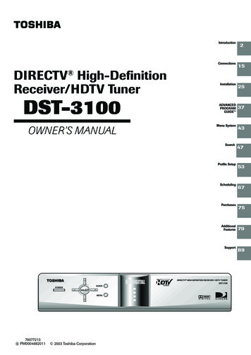
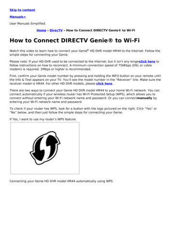
Receivers Compatible with SWM TechnologyWinegard mobile satellite TV antennas that operate with Multi-switch technology require separate accessories tooperate with DIRECTV Single Wire Multi-switch (SWM) only technology receivers. For an up-to-date list of DIRECTVDVR and non-DVR receiver models that are only compatible with SWM technology, visit www.winegard.com/directv.This website also lists Winegard mobile satellite TV antennas that are compatible with DIRECTV. If unsure of yourreceiver model, check the back of the receiver or the inside front door of the smart card slot.Winegard Mobile Satellite TV Antennas that RequireSeparate Accessories to Operate with SWM TechnologyAntennasSat 99 Sat 101 Sat 103 Sat 110 Sat 119 Wiring diagramSee page 3 for a SWM8installation, pages 7–10 foran SK-3005 combined with adome antenna***, or page 4for a SWM8 installation usingSWM1 & SWM2 outputs.See page 15 forreceiver settings.Model numberTRAV’LER SK-3005DIRECTV SlimlineSWM Kit PartsSWM8**For proper SWM operation with Winegard satellite TV antennas that operatewith Multi-switch technology, the SWM8, DIRECTV PI-28 or PI-29 powersupply, and DIRECTV approved splitter (typically 2, 4, or 8 port) must be used.Failure to use this equipment may cause issues with your system. Note thatModel SK-SWM3 SWM TRAV’LER antenna operates with DIRECTV SWMtechnology without separate accessories.The DIRECTV power inserter PI-28 or PI-29 may damage a DIRECTV receiverif improperly connected in the system. The SWM output of the power insertershould never be directly applied to the input of a receiver. During installation,verify all wiring before applying power to the power inserter.PowerInserterDIRECTV SWM8 allows the use of up to eight tuners with a Winegard satellite antenna. Count the tuners in yourSWM installation to check that there are less than or equal to eight tuners being used with SWM8. Keep in mind thefollowing when counting the number of tuners: A non-DVR receiver counts as one tuner. A DVR receiver has dual tuners and counts as two tuners (even though only one coaxial cable is needed toconnect to a DVR receiver). The exceptions are the DIRECTV Genie and HR34 DVR receivers, which have fivetuners and count as five tuners when calculating tuners for a SWM installation.Number of non-DVR receivers 2 x Number of DVR receivers Total tuners for SWM8 installationMaximum of 8 non-DVR receiversMaximum of 4 DVR receiversTRAV’LER SK-3003DIRECTV Triple LNBSplitterCalculating Tuners for SWM InstallationTotal tuners 8 for SWM8 installation**Carryout Anser *Carryout MP1 * 1Never use B-Band converters with SWM8.Do not use a DIRECTV PI-21 power inserter with a SWM8. Use a DIRECTV power inserter PI-28 or PI-29.Never power on all receivers at once. Sequentially power receivers since every receiver must get a SWM assignment.The power inserter must be installed inside the vehicle.See page 5 for a SWM8installation with domeantennas or page 4 for aSWM8 installation usingSWM1 & SWM2 outputs. Seepage 15 for receiver settings.Carryout automatic,RoadTrip Mission &MiniMax , and DuraSAT ExampleTwo non-DVR receivers and three DVR receivers are being used for a SWM8 installation.2 non-DVR receivers 2 x 3 DVR receivers 8 total tuners for SWM installationWarnings**See pages 11–12 for twowiring options for a SWM8installation or page 4 fora SWM8 installation usingSWM1 & SWM2 outputs. Seepage 15 for receiver settings.See page 6 for a SWM8installation or page 4 fora SWM8 installation usingSWM1 & SWM2 outputs. Seepage 15 for receiver settings.See page 13 for a SWM8installation or page 4 fora SWM8 installation usingSWM1 & SWM2 outputs. Seepage 15 for receiver settings.See page 14 for a SWM8installation or page 4 fora SWM8 installation usingSWM1 & SWM2 outputs. Seepage 15 for receiver settings.Crank-ups,Dish & Tripod Kits(TR-6018, PM-2000)*DIRECTV primary 101 programming only. Toggling to alternate satellites is not supported.**Availability of channels on Satellites 110 and 119 is dependent upon the satellite port to which Port C of the TRAV’LER interface is connected.***Each antenna will see satellites as listed in the above table. Note that additional parts (not included) are needed for the combined setup of theTRAV’LER antenna and domed antenna with SWM technology.2
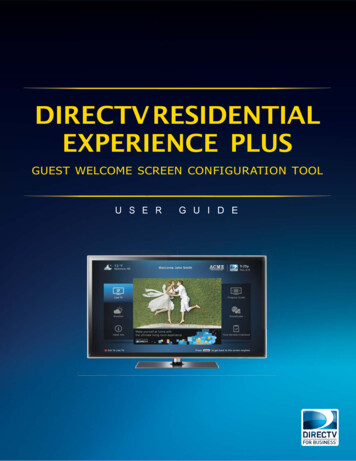
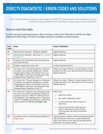
SK-3005 TRAV’LER Antenna with DIRECTV SWM8DIRECTV SWM8 Using Both SWM1 & SWM2 OutputsThe wiring diagram below applies to all Winegard satellite TV antennas that require separate accessories to operatewith SWM technology. This wiring setup does not work with whole-home DVR setup. Model SK-3005 TRAV’LERantenna is shown below.KEYCoaxial CablePower CableKEY(attached to power inserter)Coaxial CablePower CableLess than 40 ft betweenantenna & SWM8(attached to power inserter)Less than 40 ft betweenantenna & SWM8For access to 99 /101 and 103 /110 /119 satellite programming, connect all four portsof the SK-3005 TRAV’LER antenna to all fourinputs on the SWM8.*Receivers in diagram can benon-DVR or DVR receivers.*Receivers in diagram can benon-DVR or DVR receivers.Non-DVR Receiver*Non-DVR Receiver*DVR Receiver*DVR Receiver*If connecting to a DVR receiver, do not connect a coaxial cable to the Satellite 2input. With SWM, only connect to the Satellite 1 port (labeled FTM or SWM).3Terminate unusedsplitter outputswith a 75 ohmtermination cap.Note: The splitter is not required in thisdiagram. The splitter would only berequired if using more than one receiveron either the SWM1 or SWM2 output.If connecting to a DVR receiver, do not connect a coaxial cable to the Satellite 2input. With SWM, only connect to the Satellite 1 port (labeled FTM or SWM).Terminate unusedsplitter outputswith a 75 ohmtermination cap.4
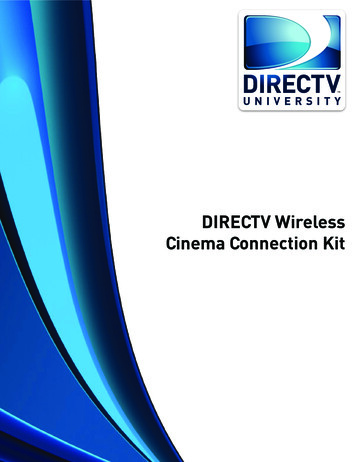
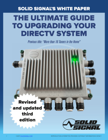
Dome Antenna with DIRECTV SWM8Carryout Anser Antenna with DIRECTV SWM8The wiring diagram below applies to dome antennas, including the Carryout GM-1518 & GM-1599, RoadTrip Mission& MiniMax and DuraSAT antennas. The diagram applies to both stationary and tracking models. Model GM-1518Carryout automatic antenna is shown below.If using an HD receiver with the Anser antenna, change the preferences setting in the Display menu to “Hide all HDChannels.” Otherwise, the antenna will appear to not be working since the receiver guide will only show HD channels.If using an HD receiver with a dome antenna, change the preferences setting in the Display menu to “Hide all HDChannels.” Otherwise, the antenna will appear to not be working since the receiver guide will only show HD channels.Less than 40 ft betweenantenna & SWM8Less than 40 ft betweenantenna & SWM8Terminate unusedSWM outputs with a 75ohm termination cap.Terminate unusedSWM outputs with a 75ohm termination cap.For access to 101 satellite programming,connect the primary and secondaryports of the antenna to both SWM inputscorresponding to Satellite 99 /101 .Coaxial CablePower Cable*Receivers in diagram can benon-DVR or DVR receivers.Non-DVR Receiver*Non-DVR Receiver*DVR Receiver*DVR Receiver*Terminate unusedsplitter outputswith a 75 ohmtermination cap.KEYCoaxial CablePower Cable(attached to power inserter)(attached to power inserter)*Receivers in diagram can benon-DVR or DVR receivers.If connecting to a DVR receiver, do not connect a coaxial cable to the Satellite 2input. With SWM, only connect to the Satellite 1 port (labeled FTM or SWM).5KEYFor access to 101 satellite programming,connect the primary and secondaryports of the antenna to both SWM inputscorresponding to Satellite 99 /101 .If connecting to a DVR receiver, do not connect a coaxial cable to the Satellite 2input. With SWM, only connect to the Satellite 1 port (labeled FTM or SWM).Terminate unusedsplitter outputswith a 75 ohmtermination cap.6
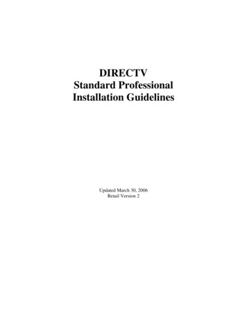
SK-3005 TRAV’LER Antenna with Dome AntennaWiring Version 1Set the Dish Type to 04: Slimline-5, and set the Switch Type to 01: SWM. For more information on receiver setupand complete step-by-step instructions, refer to your product manual, or go online to EYCoaxial CablePower CableWhen the receiver settings above are used with the SK-3005 TRAV’LER antenna, all HD and SD programming will beavailable. The same receiver settings will also work for the dome antenna but will display the “Searching for Signal”message on HD channels. To remove the “Searching for Signal” message, change the preferences setting in theDisplay menu to “Hide all HD Channels” when in dome operation. However, the receiver would need to be changedback to “Display All Channels” or “Hide All SD Duplicates” when changing back to TRAV’LER SK-3005 mode.NOTE(attached to power inserter)It may take several minutes for the DIRECTV receiver to load HD channels or to purge HD channels from thechannel guide.*Receivers in diagram can benon-DVR or DVR receivers.Non-DVR Receiver*Terminate unusedSWM outputs with a 75ohm termination cap.Terminate unusedsplitter outputswith a 75 ohmtermination cap.A/B Switch (75 ohm) SpecificationsFrequency Range (DC): 2250 MHz.Current Capacity: 2AIsolation: 25 dBInsertion Loss: .25 dBReturn Loss: 11 dB or VSWR 2:1Only one A/B switch (not included) isrequired for operation. The A/B switchmust meet the specifications above.7If connecting to a DVR receiver, do not connect a coaxial cableto the Satellite 2 input. With SWM, only connect to the Satellite1 port (labeled FTM or SWM).A/B SwitchSWITCH SETTINGSATRAV’LER AntennaBDome AntennaDVR Receiver*DCPowerPass8
SK-3005 TRAV’LER Antenna with Dome AntennaWiring Version 2Set the Dish Type to 04: Slimline-5, and set the Switch Type to 01: SWM. For more information on receiver setupand complete step-by-step instructions, refer to your product manual, or go online to hen the receiver settings above are used with the SK-3005 TRAV’LER antenna, all HD and SD programming will beavailable. The same receiver settings will also work for the dome antenna but will display the “Searching for Signal”message on HD channels. To remove the “Searching for Signal” message, change the preferences setting in theDisplay menu to “Hide all HD Channels” when in dome operation. However, the receiver would need to be changedback to “Display All Channels” or “Hide All SD Duplicates” when changing back to TRAV’LER SK-3005 mode.NOTEA/B Switch (75 ohm) SpecificationsFrequency Range (DC): 2250 MHzCurrent Capacity: 2AIsolation: 25 dBInsertion Loss: .25 dBReturn Loss: 11 dB or VSWR 2:1Two A/B switches (not included) are requiredfor operation. The A/B switches must meet thespecifications above.It may take several minutes for the DIRECTV receiver to load HD channels or to purge HD channels from thechannel guide.A/B Switch #1KEYCoaxial CablePower Cable(attached to power inserter)SWITCH SETTINGSATRAV’LER AntennaBDome Antenna*Receivers in diagram can benon-DVR or DVR receivers.Non-DVR Receiver*A/B Switch #2Terminate unusedsplitter outputswith a 75 ohmtermination cap.DVR Receiver*If connecting to a DVR receiver, do not connect a coaxial cableto the Satellite 2 input. With SWM, only connect to the Satellite1 port (labeled FTM or SWM).DCPowerPass910
SK-3003 TRAV’LER Antenna with DIRECTV SWM8SK-3003 TRAV’LER Antenna with DIRECTV SWM8Wiring Version 1Wiring Version 2All three ports of the SK-3003 TRAV’LER antenna must be connected as shown tothree inputs on the SWM8 for access to 101 odd and even transponders, 119 oddtransponder only programming.All three ports of the SK-3003 TRAV’LER antenna must be connected as shown tothree inputs on the SWM8 for access to 101 odd and even transponders, 110 and119 even transponder programming.Even (18V) transponders will not be available in Wiring Version 1.This will be verified in the receiver installation status screen shown to the right.Odd (13V) transponders will not be available in Wiring Version 2.This will be verified in the receiver installation status screen shown to the right.KEYKEYPower CablePower CableCoaxial CableCoaxial Cable(attached to power inserter)(attached to power inserter)Less than 40 ft betweenantenna & SWM8Less than 40 ft betweenantenna & SWM8Terminate unusedSWM outputs with a 75ohm termination cap.Terminate unusedSWM outputs with a 75ohm termination cap.*Receivers in diagram can benon-DVR or DVR receivers.Non-DVR Receiver*Non-DVR Receiver*DVR Receiver*DVR Receiver*If connecting to a DVR receiver, do not connect a coaxial cable to the Satellite 2input. With SWM, only connect to the Satellite 1 port (labeled FTM or SWM).11*Receivers in diagram can benon-DVR or DVR receivers.Terminate unusedsplitter outputswith a 75 ohmtermination cap.If connecting to a DVR receiver, do not connect a coaxial cable to the Satellite 2input. With SWM, only connect to the Satellite 1 port (labeled FTM or SWM).Terminate unusedsplitter outputswith a 75 ohmtermination cap.12
Crank-ups, Dish & Tripod Kits with DIRECTV SWM8Carryout MP1 Antenna with DIRECTV SWM8The wiring diagram below applies to most portable dishes and tripod kits not already covered. The coaxial connectionports can be found at the base of the LNB for crank-up antennas, dish and tripod kits. For additional tips on connectingcoaxial cables to a crank-up antenna, see the back page. Toggling to alternate satellites is not supported.Less than 40 ft betweenantenna & SWM8Less than 40 ft betweenantenna & SWM8Terminate unusedSWM outputs with a 75ohm termination cap.Note: On a crank-up antenna, thecoaxial connection ports are locatedon the base of the LNB. To connecta coaxial cable to each port, it maybe necessary to remove the roller infront of the coaxial connection ports.KEYFor access to 101 satellite programming,connect the primary and secondaryports of the antenna (located behindthe reflector) to both SWM inputscorresponding to Satellite 99 /101 .Power Cable(attached to power inserter)For access to 101 satellite programming,connect the primary and secondaryports of the antenna to both SWM inputscorresponding to Satellite 99 /101 .*Receivers in diagram can benon-DVR or DVR receivers.*Receivers in diagram can benon-DVR or DVR receivers.Non-DVR Receiver*Non-DVR Receiver*DVR Receiver*DVR Receiver*If connecting to a DVR receiver, do not connect a coaxial cable to the Satellite 2input. With SWM, only connect to the Satellite 1 port (labeled FTM or SWM).13Coaxial CableTerminate unusedsplitter outputswith a 75 ohmtermination cap.If connecting to a DVR receiver, do not connect a coaxial cable to the Satellite 2input. With SWM, only connect to the Satellite 1 port (labeled FTM or SWM).Terminate unusedSWM outputs with a 75ohm termination cap.KEYCoaxial CablePower Cable(attached to power inserter)Terminate unusedsplitter outputswith a 75 ohmtermination cap.14
DIRECTV Receiver SettingsReceiver settings are listed below for Winegard antennas using SWM technology. For more information on receiversetup and complete step-by-step instructions, refer to your satellite TV antenna manual, or go online to K-3005 TRAV’LER Antenna SettingsSet the Dish Type for 04: Slimline-5.Set the Switch Type for 01: SWM.Note that B-Band Converters should not be used with SWM Technology.SK-3003 TRAV’LER Antenna SettingsSet the Dish Type for 02: 3-LNB (18”x20”).Set the Switch Type for 01: SWM.Note that B-Band Converters should not be used with SWM Technology.Dome Antenna, Carryout Anser & MP1 Antenna,Crank-up Antenna, Dish & Tripod Kit SettingsSet the Dish Type for 01: Round (18”).Set the Switch Type for 01: SWM.Note that B-Band Converters should not be used with SWM Technology.www.winegard.com/mobileFor help, email help@winegard.com or call 1-800-788-4417Winegard Company 3000 Kirkwood St. Burlington, IA 52601-2000 800/788-4417 FAX 319/754-0787www.winegard.com Printed in U.S.A. 2012 Winegard Company Rev5 6/13 2452242Winegard, TRAV’LER, Carryout, Anser, RoadTrip, Mission, and DuraSAT are registered trademarks of Winegard Company, and MiniMax and MP1 aretrademarks of Winegard Company. DIRECTV is a registered trademark and Genie is a trademark of DIRECTV, LLC.Disclaimer: although every effort has been made to ensure that the information in this manual is correct and complete, no company shall be heldliable for any errors or omissions in this manual. Changes and technological advances are continuously being made in the satellite antenna market.Information provided in this manual was accurate at time of printing.15
This manual has been provided courtesy ofMy RV Works, Inc.www.myrvworks.comYou can find more RV service manuals here:www.myrvworks.com/manualsOver the years of running a mobile RV repair service, having a dedicated placeto access service manuals for all the different appliances and componentsfound on RVs was something that I always had a desire to create.I hope this resource makes your RV repairs easier, as it has mine, but pleasebe careful and follow proper safety practices when attempting to repairyour own RV.If in doubt, please consult with a professional RV technician!DARREN KOEPP - OWNER, MY RV WORKS, INC.All service manuals provided on www.myrvworks.com are believed to bereleased for distribution and/or in the public domain.
with Multi-switch technology, the SWM8, DIRECTV PI-28 or PI-29 power supply, and DIRECTV approved splitter (typically 2, 4, or 8 port) must be used. Failure to use this equipment may cause issues with your system. Note that Model SK-SWM3 SWM TRAV'LER antenna operates with DIRECTV SWM technology without separate accessories.