Transcription
Air Leakage of Furnaces and Air HandlersIain S. Walker, Darryl Dickerhoff, and Woody Delp, Lawrence Berkeley National LaboratoryMike Lubliner, Washington State UniversityABSTRACTIn recent years, great strides have been made in reducing air leakage in residential and toa lesser extent small commercial forced air duct systems. Several authorities have introducedlow leakage limits for thermal distribution systems; for example, the State of California EnergyCode for Buildings gives credit for systems that leak less than 6% of the total air flow at 25 Pa.Practitioners have found that a significant barrier to meeting specifications like this is the airleakage of the furnace or air handler itself. Anecdotal evidence exists for the magnitude of theair leakage of furnaces and air handlers. The states of California and Florida include air leakagelimits for the furnaces in their State Building Energy Codes. However, there is currently nostandard test method for measuring this air leakage that could be used for uniform and reliableratings. This paper presents the results of laboratory measurements air leakage testing of furnacesand air handlers. The results indicate that average air leakage is significant - confirming existinganecdotal evidence. Also, the air leakage has a wide range from furnace to furnace indicatingthat low levels of air leakage are already attainable with existing equipment and the rating for airleakage will be able to distinguish between good and poorly performing equipment. This paperwill also discuss the development of a standard test procedure (ASHRAE Standard 193 "Methodof Test for Determining the Airtightness of HVAC Equipment") that will be used by Federal,State and Local code authorities and efficiency programs as well as appliance standards, utilityprograms and a range of other applications.IntroductionThe air leakage of heating, ventilating, and air conditioning (HVAC) equipment has twomajor issues of interest:1.2.Energy waste from air leakage.Indoor Air Quality (IAQ) issues due to drawing air from crawlspaces, basements andgarages.It would be useful for codes and standards to specify tighter forced air system equipmentto supplement existing duct tightness requirements. It would also allow IAQ issues to beaddressed in a simple fashion by requiring tight equipment as well as ducting in places outsideconditioned space.One of the most important predictors of a building’s energy efficiency is its HVACsystem. There are a number of ways to measure the performance of HVAC systems—energyefficiency ratings being one of the most common—but the airtightness of the equipment isobviously an important factor as well. Air that is not delivered to areas as specified in the 2010 ACEEE Summer Study on Energy Efficiency in Buildings1-330
building design is air that is not being used efficiently. Also, air drawn from unintended areasmay bring in pollutants and result in poor indoor air quality. In recent years, much effort hasgone into the sealing of the ducts in HVAC systems; however, air leakage still remains in theheating and cooling equipment itself and is a barrier to achieving tight systems.Currently, the need for minimizing air leakage in HVAC systems is reflected in variousASHRAE standards. ASHRAE Standard 62.2 (2007) limits allowable air leakage betweengarages and houses due to leaks in forced air HVAC systems. ASHRAE Standard 152 (2004)includes HVAC system air leakage in estimates of distribution system efficiency for residentialbuildings. But while these standards aim to reduce the overall air leakage found in HVACsystems, neither provides a way to determine the effectiveness of specific components in anHVAC system in preventing air leakage.Example methods for testing forced air system leakage can be found in ASTM E1554(ASTM 2007), ASHRAE 152 (ASHRAE 2004), quality control programs such as those used bythe US Department of Energy’s DOE Building America teams, and numerous utility programs.California Building Standards currently use a variation of the test found in ASHRAE 152 andASTM E1554 in section RA 3.1.4.3 of the California Building Energy Code Joint Appendixes(CEC 2008b). The most common metric for estimating residential forced air system leakage isan air flow at a pressure difference of 25 Pa (0.1 in. water), because this metric is often used infield testing to meet the requirements of energy efficiency programs.Currently, the State of Florida is the only entity attempting to legislate on the issue offurnace leakage. Florida Building Code section 610.2.A.2.1 (2003) specifies a pressurization testwith the metric that the furnace (the Florida requirements apply to furnaces only) cannot leakmore than 2% of blower air flow at 250 Pa (1 in. water), so a furnace or air handler with anominal air flow of 500 L/s (1000 cfm) must have less than 10 L/s (20 cfm) of air leakagemeasured at 250 Pa (1 in. water). However, no specific test procedure is provided and there is noconsistency between ratings of different pieces of equipment. Because the test procedures arenot standardized, there is concern from both regulators and equipment manufacturers abouthaving a consistent basis for comparison or a “level playing field”. When developing a new teststandard there is a need to balance the manufacturers desire for simplicity of testing with areasonable amount of rigor wanted by legislators and technical experts.In the new California Building Energy code (CEC (2008a)), there is a credit for having atight air handler defined in Section 3.12.5 as a furnace with less than 2% air leakage at 250 Pa (1in. water). This is the same as the Florida requirement. Like the Florida code, the Californiacode does not specify how to do the test to ensure consistency of testing between different piecesof equipment.In Florida, actual test results are not reported. Instead, a list of complying equipment isprovided by manufacturers to the state. Some furnaces come with certification that they meet airleakage specifications. An example from one manufacturer states “Airflow leakage less than 1%of total airflow at ductblaster conditions.” It is unclear, however, what “ductblaster conditions”means. Another example from another manufacturer’s product literature states “Factory sealedto achieve 2% or less leakage rate”. It does specify a test pressure of 250 Pa (1 in. water), butnot specific test procedures. This lack of clarity and uniformity of testing is one of the reasonswhy a standard method of test is needed to produce a consistent test method for the industry touse. 2010 ACEEE Summer Study on Energy Efficiency in Buildings1-331
To address this issue, a new standard method of test has been developed by ASHRAE:ASHRAE Standard 193 "Method of Test for Determining the Air Leakage of HVACEquipment". This paper examines potential leak testing methods evaluated for inclusion in thenew standard and discusses the development of the test method used in the standard.Targeted at systems that move less than 1500 L/s (3000 cfm), Standard 193 will provideresults that may be used by cognizant authorities who wish to regulate the air leakage of HVACequipment, by contractors and installers that wish to specify and install equipment with knownleakage characteristics, and by HVAC manufacturers who wish to verify and ensure that theirapproaches to reducing the air leakage of their equipment is successful. The approach taken inStandard 193 is to determine the air leakage rate of HVAC equipment at a fixed referencepressure difference. In this way, Standard 193 is similar to other rating standards that performevaluations at a single test condition for comparison purposes rather than attempting to estimateperformance for an individual installation.Previous StudiesConcern about residential HVAC component leakage has been an issue for more than 10years. Walker et al. (1998) measured six furnaces in a field study and found an average of 11 L/s(23 cfm) at 25 Pa (0.1 in. water) or 16 L/s (34 cfm) at operating pressures measured in thefurnace outlet and blower compartment. This study also showed a large system-to-systemvariation with a standard deviation of 8 L/s (17 cfm) and a range of 3 to 24 L/s (6 to 51 cfm) at25 Pa (0.1 in. water). The furnace leakage represented 24% to 76% of total system air leakage.More recently, other researchers have performed field testing of residential HVAC equipment airleakage. The Florida Solar Energy Center (FSEC) measured air handler leakage in a study of 69Florida houses (Cummings et al. 2003). The air leakage from air handler/furnace cabinets was asignificant fraction of total leakage from the tested systems: an average of 33 L/s (70 cfm) atestimated operating pressure.Building Science Corporation (BSC) provided to the ASHRAE Standard 193 committeean overview of a study they conducted in Las Vegas, NV in 1999 in which they worked withlarge home builders to reduce forced air system air leakage. The air handlers had a leakage of 22to 28 L/s (45 to 60 cfm) at 25 Pa (0.1 in. water), about half of which was the furnace and theremainder in coil boxes and plenums. Smoke tests were used by BSC to determine leaklocations. In the air handlers, the most significant leaks occurred at the partition between theblower compartment and the wiring compartment (especially corners), and around the blowercompartment door. BSC stated that “These problems should be correctable with gaskets and/orimproved design.”As a follow-up to the BSC tests, Guaranteed Watt Saver Systems (GWSSI) performed airhandler unit (AHU) leakage tests in a laboratory. The GWSSI tests were conducted on AHUequipment more commonly used by builders in Oklahoma and Texas. AHU-alone leakage (at 25Pa (0.1 in. water)) for the seven units tested ranged from 8 to 17 L/s (18 to 35 cfm). Convertingboth the BSC and GWSSI results to operating conditions (125 Pa (0.5 in. water)) gives results inthe 19 to 33 L/s (40 cfm to 70 cfm) range similar to those observed in the field studies. GWSSItested one unit in both horizontal and vertical configurations. The test results showed a factor oftwo difference in air leakage. GWSSI observed that “the different weight distribution of the 2010 ACEEE Summer Study on Energy Efficiency in Buildings1-332
AHU components results in excessive cabinet deflection(s) between supports when placed in thehorizontal position. This causes extra openings in the cabinet’s metal folds and seams for airleakage.”Evaluation of Test Methods for Standard 193A total of five test methods were evaluated. The first two test methods use the sameprinciples as other building component air leakage tests:1.2.Whole furnace pressurization. The furnace is sealed at one end and a fan is used topressurize the furnace. The air flow needed to maintain a fixed pressure is the air leakage.Whole furnace depressurization. The furnace is sealed at one end and a fan is used todepressurize the furnace. The air flow needed to maintain a fixed pressure is the airleakageDuring initial ASHRAE Standard 193 meetings to discuss the scope and nature of the testmethod, a concern was raised over the application of a simple pressurization or depressurizationtest. For equipment with blowers, there are positive and negative pressure zones within theequipment. Negative pressure differences between inside and outside the equipment occurupstream of the blower and positive pressure differences occur downstream of the blower. It wasstated by some committee members of ASHRAE Standard 193 that the cabinet construction issuch that the efficacy of air sealing is determined by the direction of the pressure difference. Inparticular, blower access panels tend to be on the negative pressure side of the blower and will besucked onto the blower compartment when the blower operates. If a simple pressurization test isused to evaluate this equipment, the access panels will tend to be forced away from the blowercompartment and this may lead to increased air leakage.This was seen to be a valid concern by the members of the ASHRAE Standard committeeand by potential users of the Standard, such as the California Energy Commission. Therefore,Lawrence Berkeley National Laboratory (LBNL) looked at alternative methods that attempt tomaintain the same pressure direction as during normal operation for devices that have bothpositive and negative pressures. Typically, these are devices containing fans or blowers such asfurnaces, air handlers, fan powered Variable Air Volume (VAV) boxes, packaged roof top units,and other unitary equipment. This multi-pressure regime testing can be achieved in a few ways:3.4.DeltaQ. Use the blower itself to produce the test pressures. For this test method, anadaptation of the DeltaQ duct leakage test method in ASTM E1554 was developed.Zonal pressurization testing:4a.Split. The furnace is split into two parts by installing an air tight seal at theblower. This can be done one of two ways: either remove the blower and place anair tight seal in place of the blower or seal the blower inlets or outlets. Theupstream and downstream zones of the equipment can then be evaluatedindependently–with negative pressures used upstream and positive pressures useddownstream. 2010 ACEEE Summer Study on Energy Efficiency in Buildings1-333
4b.5.2 Fans. A fan is connected to each side of the equipment and both sides areequally pressurized or depressurized by nulling the pressure difference betweenthe two sides. This was done for both positive and negative pressures. The testresults are taken from the positive side during pressurization and negative sideduring depressurization.Tracer. Tracer gas concentration techniques are used to estimate air flows. For this testmethod, a method of injecting a tracer gas into the system and measuring concentrationsat various locations (together with system air flows) was developed to estimate the flowsinto and out of the equipment. The tracer test method, due to its complexity andrequirement for complex testing equipment, was intended mostly as a reference methodfor comparison to the other tests.The committee deliberated over what were appropriate test pressures by examiningsources of information on total static pressure differences (the difference between furnace outletand blower compartment pressures) and use a test value of half of this total. The first possibilitywas to be consistent with other test procedures. Existing test methods for Annual FuelUtilization Efficiency (AFUE) and Season Energy Efficiency Rating (SEER) use pressuresbetween 35 Pa to 60 Pa (0.14 to 0.24 in. water)–implying test pressures of 20 Pa to 30 Pa (0.8 to0.12 in. water) for Standard 193. However, this would result in underestimates of actual leakagebecause systems typically operate at higher pressures. A second possibility was to use total staticpressure values typically seen in new construction of 200 Pa (0.8 in. water) as observed in newCalifornia homes and presented by Wilcox et al. (2006) and given by Walker (2008) for systemswith air conditioning. For standard 193, this total would be split with half of this pressuredifference on the furnace outlet side and half on the blower compartment side ( /- 100 Pa (0.4 in.water)). This would give results that would be close to those under actual operating conditions.A third possibility was to use fan performance data on total static pressure in manufacturer’sliterature for a particular furnace at a given air flow rate. However, finding this information is notalways easy (not all manufacturers provide it in product literature) and this would be lessconsistent than using a fixed pressure. A fourth option was to use the 250 Pa (1 in. water)currently specified in Florida and California State Energy Codes for furnace air leakage testing.This was considered to be too high by equipment manufacturers. The committee finally settledon using the total static pressure difference that many manufacturers recommend as a maximumfor residential furnaces (250 Pa (1 in. water)) evenly split between the inlet and outlet side of thefurnace, i.e., 125 Pa (0.5 in. water). This was seen as a reasonable compromise betweenpressures measured in field testing and the current high pressures used in Florida and Californiaby the committee and adopted as the target test pressure difference.Laboratory Evaluation of Test ProceduresThree types of testing were performed: those involving fixed pressure testing(pressurization, depressurization and zonal pressure), DeltaQ and tracer gas. More details ofthese tests can be found in Walker et al. (2010). Although extensive measures were taken to sealthe test apparatuses used in all three test procedures, there was still some air leakage. Becausethis air leakage would be included in the measurements of equipment leakage, a background 2010 ACEEE Summer Study on Energy Efficiency in Buildings1-334
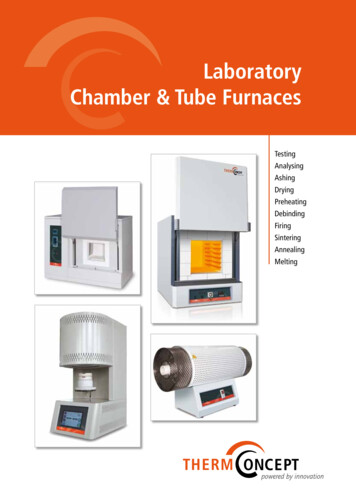
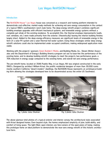
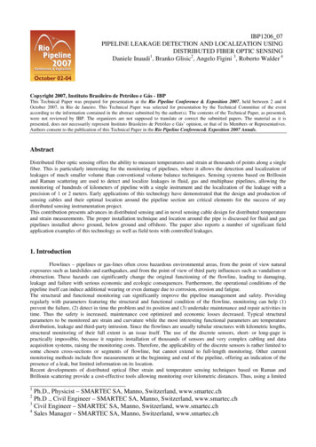
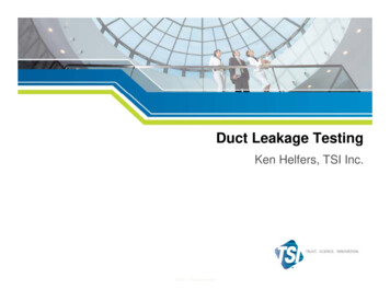
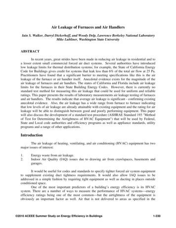
leakage test was performed so that this could be subtracted from the total measured leakage toobtain the leakage for the equipment under test only.Pressurization, Depressurization and Zonal Pressure TestingThese methods are similar to laboratory testing of building envelope components (ASTME283-04 for windows), whole house envelope leakage testing (ASTM E779-03), and ductleakage testing (ASTM E1554-07). The equipment under test has one end (the furnace outlet orthe blower compartment opening) sealed and a combination fan/airflow meter connected to theopen end to pressurize (and depressurize) the equipment under test, as illustrated in Figure 1. Airwas blown in or out at the air flow required to maintain the target 125 Pa (0.5 in. water) pressuredifference between inside the unit under test and ambient. The pressure difference was measuredat the opposite end of the equipment from where the pressurization/depressurization fan wasattached. For very low leakage values (below 5 L/s (10 cfm)), a smaller fan with a separate airflow meter (a low-flow nozzle system) was used. For zonal pressure testing, the furnace has aninternal divider installed to separate the positive and negative pressure sides of the furnace andthe two sides are measured separately.Figure 1. Roof Top Unit Undergoing a Pressurization TestDeltaQThe DeltaQ test uses the same principles as the field test for duct leakage of the samename in ASTM Standard E1554-07. It calculates air leakage at normal operating conditions, i.e.,with positive pressure on the furnace outlet side of the equipment and negative pressure on theblower compartment side. The pressures and air flows inside the ducts are created by the built-inblower together with a superimposed press from an external fan that is used to change thepressures in the duct and furnace via their connection to the test chamber. The DeltaQ test usesmeasured air flows with the equipment blower on and off over a range of pressure differences 2010 ACEEE Summer Study on Energy Efficiency in Buildings1-335
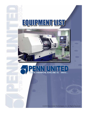
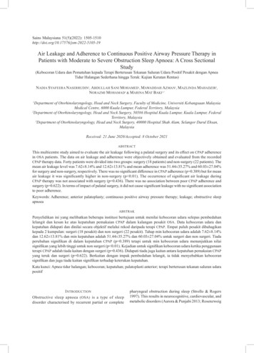
created by the external fan. Figure 2 shows the experimental apparatus for the DeltaQ tests. Theapparatus uses a test chamber with dimensions of 30 ft x 8 ft x 8 ft. The test chamber haddeliberately added air leakage of 125 L/s (250 cfm) at 25 Pa. The external fan/flowmeter wasused to operate the test chamber over a range of envelope pressures ( 100 Pa (0.4 in. water)).Dampers at the furnace inlet and outlet were used together with an in-line fan to achieve targetfurnace static pressures of 125 Pa ( 0.5 in. water) at the furnace exit and, and -125Pa (-0.5 in.water) in the blower compartment with the equipment blower running and the external fan turnedoff.The DeltaQ test has four steps:1.2.3.4.Furnace blower off, pressurization. The fan/flowmeter pressurized the test chamber andthe furnace, slowly increasing pressures and flows over about 90 seconds from zero toabout 125 Pa (0.5 in. water).Furnace blower on, pressurization. Step one is repeated with the furnace blower on.Furnace blower on, depressurization. The fan/flowmeter depressurized the test chamberand the furnace, with the furnace blower on.Furnace blower off, depressurization. The final step repeats step 3 with the furnaceblower off.The differences between furnace blower on and off data are used in a mathematical airflow model of the test chamber and duct system (developed by Walker et al. (2001) and outlinedin ASTM E1554) to estimate the leakage flow in and out of the furnace.Figure 2. Sketch and Photograph of DeltaQ Test ApparatusFigure 3 shows example DeltaQ test data. The first plot shows the individual air flowmeasurements with the blower on and off. The second plot shows the differences between thefan on and off data binned every 1 Pa (0.004 in. water) of chamber pressure. The error bars in 2010 ACEEE Summer Study on Energy Efficiency in Buildings1-336
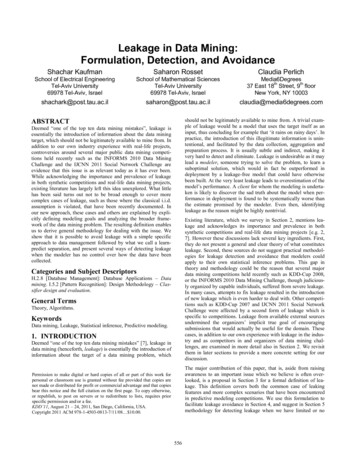
the second plot are calculated by combining the standard deviations of the on and off data in thebin in quadrature (i.e., the square root of the sum of the standard deviations squared). TheDeltaQ function (from ASTM E1554-2007) was used to estimate the air flows in and out of thefurnace by fitting to the airflow difference data in the second plot. The resulting function isshown by the solid curve in the right-hand plot.Tracer GasLike DeltaQ, the tracer gas test attempts to measure the leakage under normal operatingconditions using the furnace (or air handler) blower to create positive and negative pressures inthe equipment under test. Figure 4 illustrates the test apparatus for the tracer gas tests. Theequipment under test is placed in one test chamber. Ducts from the equipment pass into a secondtest chamber. The tracer gas (CO2) is injected at the flow nozzle inlet which is also the wherereturn air flows into the duct system. The tracer gas concentrations are combined withmeasurements of air flows at critical parts of the duct/equipment system to allow the calculationof air flow into and out of the equipment under test. As with the DeltaQ testing, dampers wereused to achieve the target static pressure differences of 125 Pa in the furnace outlet and blower.Figure 3. DeltaQ Example Data and Test Results 2010 ACEEE Summer Study on Energy Efficiency in Buildings1-337
Figure 4: Tracer Gas Test ApparatusTracer gas concentrations were measured at the entry to the furnace, at the exit of theducting, in the furnace chamber and outside the test chambers. The total furnace blower flowwas measured with an in-line nozzle flow meter. A sample pump was used to draw continuouslyfrom these locations. Every two to four minutes, a sample was taken to an infrared analyzer thatprovides the concentration of tracer gas in the sample. A mass balance was used to determinethe air flows in and out of the furnace.The tracer gas testing presented two major challenges that make it difficult to recommendas a standardized test method. The first challenge deals with mixing issues. It is difficult toensure complete mixing of the furnace outlet leakage with the air in chamber #2 before this airwas drawn back into the furnace by the return leakage. This potential short-circuiting results in ahigher Cs and lower Cc than the perfect mixing assumed in the mass balance calculations.Another mixing issue deals with how well the tracer gas is mixed after injection into the returnducting. To improve the mixing inside the return duct an inline fan was used. Additional mixingfans were also used in both test chambers. In developing this test, the sample locations weremoved around outside the furnace to examine spatial variations that would indicate incompletemixing. Analysis of the samples indicated that the concentration was uniform to within 10%.The second challenge in using the tracer gas method was that the analysis is only valid at,or very near to, steady-state conditions, i.e., when the tracer gas concentrations no longer changewith time. In the furnace leakage experiments, the leakage flows are small compared to thevolume of the test chambers, so it took about five hours for steady-state conditions to be reached. 2010 ACEEE Summer Study on Energy Efficiency in Buildings1-338
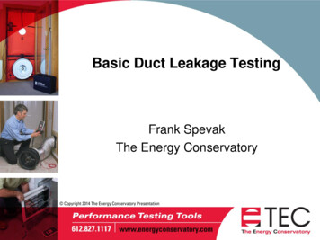
Figure 5. Schematic and Photograph of Small Test Chamber DeltaQ FurnaceCabinet Leakage ApparatusSmall Chamber Furnace Testing at IBACOSThe need for a large test chamber described earlier represents a cost barrier to widespreadDeltaQ and tracer gas testing by equipment manufacturers and others. To see if a less expensivetest apparatus could be used, the DeltaQ tests were repeated using a small test chamber at the testlaboratories of IBACOS in Pittsburgh (shown in Figure 5). The hole is required in the testchamber to create an airflow path that allows for differences in air flows and changes in these airflows under different test chamber pressures. The dampers are used during the DeltaQ testing tocontrol the furnace outlet and blower compartment pressures. This proved to be a very difficulttask such that the target pressures of 125 Pa ( 0.5 in. water) were not achieved. One reason forthis is the cross talk between the two damper adjustments. As each damper is closed the air flowthrough the system is reduced – leading to reductions in pressure in the plenum whose damperwas not being adjusted. As the dampers are progressively closed in an iterative manner,eventually the flow is choked to the point where the blower fan stalls. This is the second reasonfor not achieving the target pressures: some blowers are not rated at a full inch (250 Pa) of staticpressure difference and do not work at these high static pressure differences. Therefore, thedamper settings were limited to achieve a reasonable pressure difference without reaching thepoint of blower stall.ResultsThree furnaces and a rooftop package unit (RTU) were tested at the LBNL laboratory.The three furnaces had blower compartment doors that were friction fits with no gaskets or seals. 2010 ACEEE Summer Study on Energy Efficiency in Buildings1-339
The RTU had a blower compartment door with a foam rubber gasket. Two additional furnaceswere tested at the IBACOS test laboratory.Repeatability of testing was evaluated by performing tests multiple times. Theinstrumentation was completely removed and the apparatus re-set to simulate the uncertainty asif the testing was done in different laboratories (with the same instrumentation). In Tables 1through 3, the values following the sign represent the standard deviations of the multiple tests.Fan cases with only 2 or 3 repeated tests the range is given.LBNL Furnace and Component LeakageFor the pressurization testing the leakage of the blanking plate and collar was below theresolution of the measurement equipment (less than 0.5 L/s (1 cfm)). For the DeltaQ and tracergas testing the nature of the tests and the way the apparatus was constructed and operated meantthat the test apparatus leakage was not included in the measurement. For example, in the tracergas testing the concentration of tracer entering the furnace was measured after any leakage intothe apparatus.The first furnace (nominal air flow 470 L/s (1000 cfm)) had the whole furnacepressurization test performed ten times and the DeltaQ test six times. The repeated test resultsindicate a standard deviation of about 10% of the measured leakage - about 4 L/s (8 cfm) forthis furnace. Examining the whole furnace pressurization results in more detail shows that, if thefurnace is not moved from test to test, the repeatability is much better at about 1.5 L/s (3 cfm).The big changes occur when the furnace is moved in and out of the test apparatus. It was alsoobserved during testing that small changes to the blower access panel fitting would significantlychange the air leakage. Thus, the standard deviation for the testing is due to the furnace itselfchanging leakage as well as the repeatability of the test method. This can be thought of ascapturing the test-to-test variability for different laboratories testing the same furnace, but havingthe furnace cabinet components shift during transportation and installation in each test apparatus.This variability due to subtle shifts in furnace component panels was also observed in previoustesting by GWSSI.For furnace #1, the tests that separated the leakage in the positive and negative pressurezones showed that the majority of the air leakage was in the negative pressure zone. Also for thisfurnace, whole furnace pressurization gave higher leakage results than depressurization. Thetracer gas results are consistently lower than results for the other tests. Given the caveats aboutmixing problems with this testing, we believe that these test results are due to experimental errorfor the tracer testing.To see how much the furnace air leakage could be improved, the visible leaks weresealed with duct tape and the negative pressure zone was retested using the split zonalpressurization method. Surprisingly, there was no observed reduction in the measured airleakage. 2010 ACEEE Summer Study on Energy Efficiency in Buildings1-340
Table 1. Air Leakage Test Results for Furnace #1 in LBNL LaboratoryTestWhole FurnacePressurizationWhole FurnaceDepressurizationDeltaQSplitTracerAll leaks sealedSplit.Return onlyPositive pressure zoneleakage, L/s (cfm)Negative pressure zoneleakage, L/s (cfm)Total Leakage, L/s (cfm)40 4 (84 8)30 (64)10 1 (21 2)6 (13)5 (10)29 3 (62 6)27 (57)15 (32)28 (60)39 (83)33 (70)20 (42)The second furnace (nominal air flow 565 L/s (1200 cfm)) had the whole furnacepressurization test performed five times, the DeltaQ test three times, and the tracer gas testingthree times. For whole furnace pressurization, the standard deviation was of about 15% of themeasured leakage-about 4.5L/s (9 cfm). As for Furnace #1, examining the whole furnacepressurization results in more detail shows that, if the furnace is not moved from test to test, therepeatability is much better: for the three tests on one day of testing the variability was 2% to 5%of measured leakage (0.5 to 1.5 L/s (1 to 2.5 cfm)). Once again, the big changes
Code for Buildings gives credit for systems that leak less than 6% of the total air flow at 25 Pa. Practitioners have found that a significant barrier to meeting specifications like this is the air leakage of the furnace or air handler itself. Anecdotal evidence exists for the magnitude of the air leakage of furnaces and air handlers.