Transcription
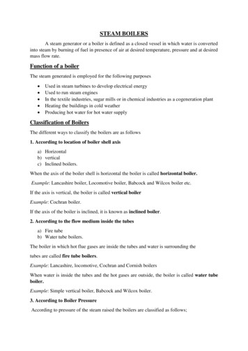
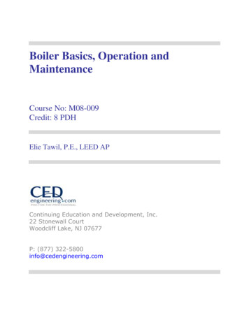
Series 211ACommercialAtmospheric Gas Boiler Packaged, Assembled Block*or Individual SectionsNatural Draft Venting630 to 9,450 MBH InputSteam or Hot Water BoilersNatural or LP Gas Boiler efficiencies are compliant with federaland ASHRAE 90.1 requirements. Optional Mod-U-Pak unique three-stage firing The versatility, reliability and simplicity of the Series 211A make it aviable alternative to forced draft boilers. It’s easier to install, easierto start up and easier to service—all with fewer moving parts.system provides improved boiler response andfuel economy.Built-in horizontal to vertical draft hood andaluminized steel flue collector provide a lowboiler profile to allow installation in areas withlow head room.The unique finned, tubular sections are spacedevenly using spacing rings which allow thesections to maintain their as-cast skin, providingmaximum corrosion resistance and longer life.The Flow Port flexible seals assure a watertight fit while providing faster boiler assemblyand allow the sections to expand and contractindependently.The exclusive access design, from both ends,allows easy accessibility to the flueways forinspection and cleaning, without removing theentire jacket.Optional tankless coils can be used to assureadequate domestic hot water production onwater boilers only.SERIES 211A PACKAGED BOILER RATINGSSeries t I B R 4.92102.83110.74118.65126.56134.47142.38150.291 Net I B R water ratings based on an allowance of 1.15.2 Net I B R steam ratings based on an allowance of: 04 to 08 1.333, 09(Nat) 1.324, 09(LP) 1.327, 10(Nat) 1.310, 10(LP) 1.312, 11(Nat) 1.298, 11(LP) 1.300,12(Nat) 1.290, 12(LP) 1.291, 13 to 19 1.288.3 Consult factory before selecting a boiler for installation having unusual piping and pickup requirements, such as intermittent system operation, extensive piping systems, etc.4 Combustion efficiency determined in accordance with ANSI Z21.13, Gas-Fired Low-Pressure Steam and Hot Water Boilers.* Assembled blocks available to 19 sections only.
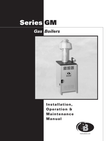
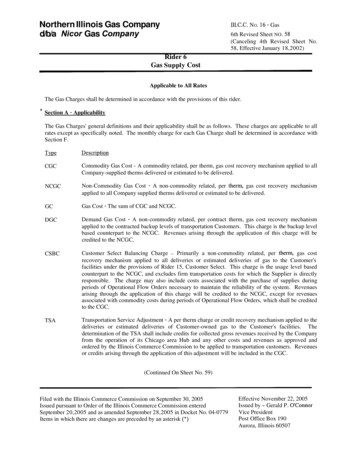
ASSEMBLED BLOCK WITH INSULATED BASEINDIVIDUAL FINNED SECTIONSIndividual Finned Sections: the proven finnedtubular design combines the best of cast iron andwater tube boilers—superior strength withoutadded weight and wide spacing in the flueways.Insulated Base: Modular insulated steel baseinsures the correct fit of the sections and simplifieshandling and assembly.SERIES 211A ASSEMBLED BLOCK* OR INDIVIDUAL SECTION BOILER RATINGSNATURAL GASBoilerModelNumber“S” or“W”4InputMBHOutputMBHSteamSq. 95,4055,5515,6975,8435,9906,1366,2826,4286,574LP GAS 2500 B.T.U.Net I B R Ratings3Thermal 95.7200.8205.8210.8215.8220.8225.81¹ ₄1¹ ₄1¹ ₄1¹ ₂1¹ ₂222222¹ ₂2¹ ₂2¹ ₂2¹ ₂2¹ ₂(2) 2(2) 2(2) 2(2) 2(2) 2(2) 2(2) 2(2) 2¹ ₂(2) 2¹ ₂(2) 2¹ ₂(2) 2¹ ₂(2) 2¹ ₂(2) 2¹ ₂(2) 2¹ ₂(2) 2¹ ₂(2) 2¹ ₂(2) 2¹ ₂(2) 2(2) 2(2) 2¹ ₂(2) 2¹ ₂(2) 2¹ ₂(2) 2¹ ₂(2) 2¹ ₂(2) 2¹ ₂(2) 2¹ ₂(2) 2¹ ₂(2) 2¹ ₂Net I B R Ratings3InputMBHOutputMBHSteamSq. 634,7064,8494,9915,134111¹ ₄1¹ ₄1¹ ₄1¹ ₂1¹ ₂22222222¹ ₂2¹ ₂(2) 2(2) 2(2) 2(2) 2(2) 2(2) 2(2) 2(2) 2(2) 2(2) 2(2) 2(2) 2(2) 2(2) 2(2) 2¹ ₂(2) 2¹ ₂(2) 2¹ ₂(2) 2¹ ₂BOILER MODEL NUMBERS 211A-38 TO 211A-46ARE CERTIFIED FOR NATURAL GAS ONLY.CONTACT THE FACTORY.1 Net I B R water ratings based on an allowance of 1.15. 2 Net I B R steam ratings based on an allowance of: 04 to 08 1.333, 09(Nat) 1.324, 09(LP) 1.327, 10(Nat) 1.310,10(LP) 1.312, 11(Nat) 1.298, 11(LP) 1.300, 12(Nat) 1.290, 12(LP) 1.291, 13 to 46 1.288. 3 Consult factory before selecting a boiler for installation having unusual piping andpickup requirements, such as intermittent system operation, extensive piping systems, etc. 4 Combustion efficiency for all models is 80.0% and is determined in accordance withANSI Z21.13, Gas-Fired Low-Pressure Steam and Hot Water Boilers.* Assembled blocks available to 19 sections only.
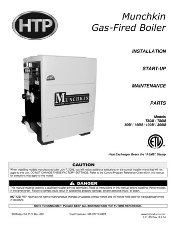
BOILER DIMENSIONSDimensionsBoiler Length & Width BoilerModelSectionNumber “A” “B” “C” Length mediate Riser Center Lines 3" Tappings – Used in Additionto Two End Risers (STEAM ONLY) (Dimension are Approximate)“E”“F”“G”28¹ ₈"33³ ₄"39³ ₈"45"50⁵ ₈"38³ ₈"44"50¹ ₄"55⁷ ₈"61³ ₄"63"63"65"63"63"21³ ₄"27³ ₈"33"38⁵ ₈"44¹ ₄"56¹ ₄"61⁷ ₈"67¹ ₂"73¹ ₈"78³ ₄"67⁵ ₈"73¹ ₄"80³ ₄"86³ ₈"91¹ ₂"63"65"65"63"63"49⁷ ₈"55¹ ₂"61¹ ₈"66³ ₄"72³ ₈"84³ ₈"90"95⁵ ₈"101¹ ₄"106⁷ ₈"97¹ ₈"102³ ₄"108³ ₈"114¹ ₄"120³ ₈"65"65"65"65"65"78"83⁵ ₈"89¹ ₄"94⁷ ₈"100¹ ₂"112¹ ₂"118¹ ₈"123³ ₄"129³ ₈"135"139¹ ₈"144³ ₄"150³ ₈"156"161⁵ ₈"65"65"65"65"65"106¹ ₈"111³ ₄"117³ ₈"123"128⁵ ₈"140⁵ ₈"146¹ ₄"151⁷ ₈"157¹ ₂"163¹ ₈"166³ ₈"172"177⁵ ₈"183¹ ₄"188⁷ ₈"65"65"65"65"65"134¹ ₄"139⁷ ₈"145¹ ₂"151¹ ₈"156³ ₄"47⁷ ₁₆"36³ ₁₆"36³ ₁₆"36³ ₁₆"24¹⁵ ₁₆"45"33³ ₄"33³ ₄"28¹ ₈"33³ ₄"33³ ₄"39³ ₈"28¹ ₈" 28¹ ₈"33³ ₄" 33³ ₄"168³ ₄"174³ ₈"180"185⁵ ₈"191¹ ₄"194¹ ₂"200¹ ₈"205³ ₄"211⁷ ₈"217¹ ₂"65"65"65"65"65"162³ ₈"168"173⁵ ₈"179¹ ₄"184⁷ ₈"24¹⁵ ₁₆"30⁹ ₁₆"30⁹ ₁₆"30⁹ ₁₆"24¹⁵ ₁₆"28¹ ₈"28¹ ₈"22¹ ₂"28¹ ₈"22¹ ₂"28¹ ₈"28¹ ₈"22¹ ₂"22¹ ₂"22¹ ₂"28¹ ₈"28¹ ₈"22¹ ₂"22¹ ₂"22¹ ₂"196⁷ ₈"202¹ ₂"208¹ ₈"213³ ₄"223⁷ ₈"229¹ ₂"262"268"65"65"65"65"190¹ ₂"196¹ ₈"201³ ₄"207³ ₈"24¹⁵ ₁₆"24¹⁵ ₁₆"24¹⁵ ₁₆"24¹⁵ ₁₆"22¹ ₂"22¹ ₂"22¹ ₂"22¹ ₂"22¹ ₂"22¹ ₂"22¹ ₂"22¹ ₂"22¹ ₂"28¹ ₈"22¹ ₂"22¹ ”“O”Flue Connection Center Lines“P” “AA” “BB” “CC” “DD” “EE” “FF” “GG” “HH” “II” “FF”10⁷ ₈"13³ ₄"16¹ ₂"10⁷ ₈" 16⁷ ₈"13³ ₄" 19⁵ ₈"10⁷ ₈"13⁵ ₈"16¹ ₂"10⁷ ₈"10⁷ ₈"13³ ₄"16¹ ₂"16¹ ₂"13³ ₄"13³ ₄"22¹ ₂"25³ ₈"28¹ ₈"22¹ ₂" 19⁵ ₈"22¹ ₂" 22¹ ₂"13⁵ ₈"13⁵ ₈"16¹ ₂"10⁷ ₈"13⁵ ₈"53¹ ₁₆"16¹ ₂"16¹ ₂"16¹ ₂"13³ ₄"47⁷ ₁₆" 16¹ ₂"25³ ₈"25³ ₈"28¹ ₈"22¹ ₂"25³ ₈"22¹ ₂"25¹ ₄"28¹ ₈"22¹ ₂" 22¹ ₂"22¹ ₂" 22¹ ₂"13⁵ ₈"16¹ ₂"16¹ ₂"13⁵ ₈"13⁵ ₈"53¹ ₁₆"58¹¹ ₁₆"58¹¹ ₁₆"41¹³ ₁₆" 45"41¹³ ₁₆" 45"53¹ ₁₆"53¹ ₁₆"58¹¹ ₁₆"36³ ₁₆"41¹³ ₁₆"13³ ₄"16¹ ₂"16¹ ₂"16¹ ₂"16¹ ₂"25³ ₈"28¹ ₈"28¹ ₈"25³ ₈"28¹ ₈"28¹ ₈"28¹ ₈"28¹ ₈"22¹ ₂"25³ ₈"25¹ ₄"25³ ₈"28¹ ₈"22¹ ₂" 22¹ ₂"22¹ ₂" 22¹ ₂"13⁵ ₈"13⁵ ₈"16¹ ₂"13⁵ ₈"13⁵ ₈"41¹³ ₁₆"36³ ₁₆"36³ ₁₆"30⁹ ₁₆"30⁹ ₁₆"16¹ ₂"16¹ ₂"16¹ ₂"16¹ ₂"16¹ ₂"28¹ ₈"28¹ ₈"28¹ ₈"28¹ ₈"28¹ ₈"28¹ ₈"28¹ ₈"28¹ ₈"25³ ₈"28¹ ₈"25³ ₈"28¹ ₈"28¹ ₈"22¹ ₂"25³ ₈"22¹ ₂"25³ ₈"28¹ ₈"22¹ ₂" 22¹ ₂"22¹ ₂" 22¹ ₂"13⁵ ₈"13⁵ ₈"16¹ ₂"13⁵ ₈"13⁵ ₈"28¹ ₈"28¹ ₈"22¹ ₂" 22¹ ₂"22¹ ₂" 22¹ ₂"22¹ ₂" 22¹ ₂" 22¹ ₂"24¹⁵ ₁₆"24¹⁵ ₁₆"30⁹ ₁₆"30⁹ ₁₆"24¹⁵ ₁₆"16¹ ₂"16¹ ₂"16¹ ₂"16¹ ₂"16¹ ₂"28¹ ₈"28¹ ₈"28¹ ₈"28¹ ₈"28¹ ₈"28¹ ₈"28¹ ₈"28¹ ₈"28¹ ₈"28¹ ₈"28¹ ₈"28¹ ₈"28¹ ₈"25³ ₈"28¹ ₈"25³ ₈"28¹ ₈"28¹ ₈"22¹ ₂"25³ ₈"22¹ ₂"25³ ₈"28¹ ₈"22¹ ₂" 22¹ ₂"22¹ ₂" 22¹ ₂"13⁵ ₈"13⁵ ₈"16¹ ₂"13⁵ ₈"13⁵ ₈"28¹ ₈"28¹ ₈"22¹ ₂"22¹ ₂"24¹⁵ ₁₆"24¹⁵ ₁₆"19⁵ ₁₆"24¹⁵ ₁₆"16¹ ₂"16¹ ₂"16¹ ₂"16¹ ₂"28¹ ₈"28¹ ₈"28¹ ₈"28¹ ₈"28¹ ₈"28¹ ₈"28¹ ₈"28¹ ₈"28¹ ₈"28¹ ₈"28¹ ₈"28¹ ₈"28¹ ₈"28¹ ₈"28¹ ₈"25³ ₈"25³ ₈"28¹ ₈"28¹ ₈"22¹ ₂"13⁵ ₈"13⁵ ₈"16¹ ₂"13⁵ ₈"BOILER MODEL NUMBERS211A-04-S TO 211A-17-S INCLUSIVEDO NOT INCORPORATEINTERMEDIATE TAPPED SECTIONS22¹ ₂"22¹ ₂"22¹ ₂"22¹ ₂"22¹ ₂"22¹ ₂"22¹ ₂" 22¹ ₂"22¹ ₂" 22¹ ₂"22¹ ₂"22¹ ₂"28¹ ₈"22¹ ₂" 22¹ ₂"
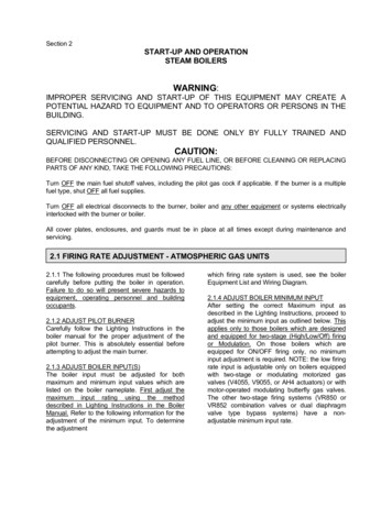
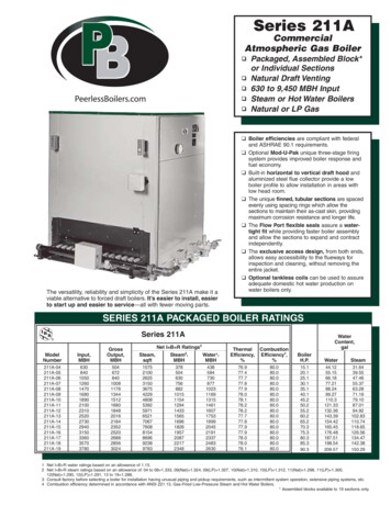
PIPING DIAGRAM1–The supply and return connection should be sized to suit the system. Utilize allintermediate tapped sections. Refer to boiler tappings chart.1–A header and equalizing line should beused on all pumped return systems.2–A header, equalizing line and HartfordLoop should be installed with a gravitysystem.3–The return from system should enterthe equalizer line through the HartfordLoop, 2 to 4 inches below the water line.4–An equalizer line should be installed onboth ends of the boiler starting with the211A-16.Loc. of Inter.BoilerTapped Sects.Model Counting from 1A-37C/L of Inter. Tap.Sects. Meas. fr. LeftSide of Blk. (Water)(Dimens. Approx.)Loc. of Inter.Tapped Sects.Counting from -5"2-6"2-6"2-6"2¹ ₂"2¹ ₂"2¹ ₂"2¹ ₂"2¹ ₂"2¹ 5"5"5"5"5"5"5"5"5"5"5"5"5"5"DO NOT 9-13-17-21-25-29-33INTERMEDIATE TAPPED SECTIONSBoilerModel W211A-10Wthru211A-15W211A-16Wthru211A-46W53¹ ₁₆" 109⁵ ₁₆"58¹¹ ₁₆" 114¹⁵ ₁₆"53¹ ₁₆" 120⁹ ₁₆"58¹¹ ₁₆" 126³ ₁₆"69¹⁵ ₁₆" 137⁷ ₁₆"47⁷ ₁₆" 92⁷ ₁₆" 143¹ ₁₆"47⁷ ₁₆" 98¹ ₁₆" 148¹¹ ₁₆"69¹⁵ ₁₆" 114¹⁵ ₁₆" 159¹⁵ ₁₆"69¹⁵ ₁₆" 114¹⁵ ₁₆" 159¹⁵ TANKLESS WATER HEATERBOILER MODEL NUMBERS211A-04-W TO 211A-28-W INCLUSIVESTEAM ONLYTwoTwoHeaterHeaterHeatersHeatersNo. X-1051 No. X-1052 No. X-1051 No. 1.012.08.013.08.013.0Only one water heater canbe used on these modelsbecause of boiler length.16.0—16.026.0Only one water heater canbe used on these models.Boiler sizes require pipinggreater than 2-3" taps.Water heater ratings are based on constant demand—40 F to 140 Frise with 200 boiler water.CAUTION: Water mixing valve should always be installed in the hotwater supply to prevent injury.NOTE: In areas having hard water, water with high oxygen content orother unusual water condition, the use of Direct Hot Water SupplyBoilers should be considered only with proper water treatment.
SERIES 211A BOILERFEATURES, ADVANTAGES AND BENEFITSPRECISION GROUND SPACING RINGSWater tube sections are evenly spaced using spacing rings to avoid longiron-to-iron contact. This allows the sections to retain their natural (as cast)skin and provides maximum corrosion resistance and longer life. Sectionsare designed to be pulled together, section-by-section (using individualdraw-rods), as the boiler is assembled. Spaces between sections aresealed with a compressible, heat resistant rope, forming a permanent, gastight joint and to allow for expansion and contraction of boiler.FLOW PORT GASKET SEALINGThe Series 211A boiler features a unique method for sealingsections. Each section’s flow port has a machined recess(Fig. A) which holds the flow port gasket. The opposite sidehas a flat machined surface (Fig. B) which compresses thegasket when sections are drawn together with the individualshort draw-rods. This assures a water-tight seal and permitsfaster boiler assembly.Figure AFigure BALUMINIZED STEEL FLUE COLLECTORThis boiler is equipped with Aluminized Steel Flue Collectors andHorizontal-to-Vertical Draft Diverters for extra long life. Thisassembly maintains a predetermined height of the flue outletregardless of boiler size. High chimneys and forced (or induced)draft are not required for efficient operation.ACCESS DOORS AT BOTH ENDS OF BOILERInspection and cleaning of the flueways in a Series 211A boiler aremore convenient since they can be accomplished from either end.Two (2) jacket sections (one at each end of the boiler) may be takenout without removing the jacket. This permits easy removal of jacketpanels and provides access to the insulated, heavy steel doorsmounted directly to the end sections.
SERIES 211A BOILER SPECSSERIES 211A INFORMATIONBoilerModelNumberGasConnection Size(Nat. 211A-32211A-33211A-34211A-35211A-361"1"1¹ ₄"1¹ ₄"1¹ ₄"1¹ ₂"1¹ ₂"2"2"2"2"2"2"2"2¹ ₂"(2) 2"(2) 2"(2) 2"(2) 2"(2) 2"(2) 2"(2) 2"(2) 2"(2) 2"(2) 2"(2) 2"(2) 2"(2) 2"(2) 2"(2) 2"(2) 2¹ ₂"(2) 2¹ ₂"(2) 2"Draft HoodsNo. & (7)Flue Sizeto "31"32"32"33" Low Water Cutoff (Except KD Water) Removable End Cleanout Panels 120 V Main Gas Valves Honeywell Electronic Ignition System100% Shutoff – Natural Gas OnlyWater 30 PSI Safety Relief Valve Temperature-Pressure GaugeSteam Gauge Glass and Fittings Pressure Gauge 15 PSI Safety 00637068007400795084208900945010000PRODUCT SELECTION GUIDESTANDARD EQUIPMENT Cast Iron Sections—Factory Tested Insulated Enameled Steel Jacket Horizontal to Vertical Draft Diverters Assembled Gas Control Train to MeetANSI Z21.13Includes: Main and Pilot S.O. Valves,Main and Pilot Gas Press. Reg. andTwo (2) Auto. Safety S.O. Valves Limit Control Manual Reset Operating Control Aluminized Steel Flue Collectors Aluminized Steel pping Weight(lbs.)Example:211A – 04 – WP – STD – 7" WC – 30 PSISeriesSects.W, WP, S or SP*5" WC, 7" WC,10" WCSTD, IRI, FM or CSD*WWPSSP Water Knockdown Water Package Steam Knockdown Steam Package15305080PSI Steam (Std.)PSI Water (Std.)PSIPSIOTHER OPTIONAL EQUIPMENTInsurance Control System:Complete systems to meet insurancerequirements, GE GAP, FM, etc. areavailable. Consult factory forinformation.MOD-U-PAK Control SystemThe Mod-U-Pak system provides threestage modulation of gas input to theboiler as needed to meet heatingrequirements and outdoor temperaturechanges, with a minimum of gasconsumption, providing efficient systemoperation.CUT-211A R14 (10/08-5M), Printed in U.S.A.Electronic Controls: A variety ofPeerless Electronic Control Systemsare available. These include pre-wiredcontrol panels with multiple signal lightsand switches to suit application. Referto ECP literature.ASMEPeerlessBoilers.com 2008
SERIES 211A ASSEMBLED BLOCK* OR INDIVIDUAL SECTION BOILER RATINGS Boiler Model Number "S" or "W"4 NATURAL GAS LP GAS 2500 B.T.U. Input MBH Output MBH Net I B R Ratings3 Thermal Effy. Comb. Effy. Boiler H.P. Gas Conn. Size (in.) Input MBH Output MBH Net I B R Ratings3 Gas Conn. Size (in.) Steam Sq. Ft. Steam MBH2 Water MBH1 Steam Sq. Ft .