Transcription
A Hardware Designer'sInformal Guide toXilinx Zynq UltraScale By Fidus SystemsFor Anyone Interested in Learning MoreVersion: 1.02020-04-06
A Hardware Designer's Informal Guide to Zynq UltraScale Version: 1.02020-04-06Revision HistoryRevisionAuthorRelease DateDescription of 6Initial Draft (incomplete)Initial Draft (complete, ready for review)Updated following review. Released.Confidential2
A Hardware Designer's Informal Guide to Zynq UltraScale Version: 1.02020-04-06Table of Contents1Introduction . 52The Tips . 62.1Selecting your Device . 62.2MIO Structure and Function Assignment. 82.3PS MIO Bank Voltage. 122.4Extended Multiplexed IO (EMIO) . 122.5Bank 503. 132.6Other Dedicated Pins . 142.7PS and PL System Monitor . 152.8PS Transceivers (GTRs) . 162.9PCIe . 182.10Powering the Zynq US . 192.11Thermals. 212.12Device Configuration . 222.13PL HP and HD. 232.14PS and PL DDR . 232.15PL Transceivers . 252.16Clocks . 262.16.12.16.22.1734PS Clocks . 26PL Global Clocks. 27XTP427 Schematic Checklist. 27Debug Peripherals Every Zynq US Design Should Have . 273.1Reset Switches . 273.2Status LEDs . 273.3Debug Headers . 283.4Boot Mode Configuration . 283.5Spare Clocks . 283.6SecureDigital . 28Typical Zynq UltraScale Applications . 294.1Video Streaming . 294.2Compute Offload and Acceleration . 304.3Storage . 31Confidential3
A Hardware Designer's Informal Guide to Zynq UltraScale Version: 1.02020-04-065About Fidus Systems. 346References . 356.1General Zynq US References . 35DisclaimerThis article is provided for the User’s enjoyment. All information contained herein is believed to be correct. It ispossible that some information is incorrect, misleading, or out-dated. We recommend that the informationcontained herein be used as a guide only, and that the User reviews all claims, concerns, or design decisions, withXilinx, Xilinx’s official information, and/or Xilinx’s representatives (i.e. Avnet). Fidus cannot be held responsible forlosses or damages associated with the use or misuse of the information within article. Use of this article and theinformation contained is at User’s own risk.The views and opinions expressed in this article are those of the author(s) and do not necessarily reflect theofficial policy or position of Fidus Systems.Fidus Systems assumes no responsibility or liability for any errors or omissions in the content of this article. Theinformation contained in this article is provided on an "as is" basis with no guarantees of completeness, accuracy,usefulness or timeliness.Fidus Systems is a Xilinx Premier Design Services Member. Fidus does not represent or pretend to represent Xilinx.Confidential4
A Hardware Designer's Informal Guide to Zynq UltraScale Version: 1.02020-04-061 IntroductionAfter delivering more than twenty (20) Zynq UltraScale (Zynq US ) designs last year, Fidus can truly say thatthey are expert implementers of the latest Multi-Processor System On-a-Chip (MPSoC; pronounced em-pee-sok)technology from Xilinx . These designs spanned multiple applications and markets. This whitepaper is targeted atpeople who are generally familiar with the Zynq US and are either, a) Considering Zynq US for their next design,b) Want to gain insight into some common Zynq US applications, and/or c) Frankly, potential Customers who areconsidering Fidus for their next custom Zynq US design. This paper can also be used as a guide to the most‘design critical’ Xilinx Zynq US reference documents.I’m Scott, a hardware designer by trade, so this document focuses mostly on the actual hardware aspects relatedto Zynq US . And let’s face it, a paper on Zynq US FPGA and Software development would be several thousandpages long as the chip can do pretty much anything.Hope you enjoy and find this article of value. Feel free to reach out via the contact information provided at theend.Confidential5
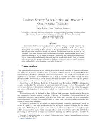
A Hardware Designer's Informal Guide to Zynq UltraScale Version: 1.02020-04-062 The TipsThis section describes some of the most valuable knowledge and interesting resources I’ve come across whendesigning with the Zynq US . It is my hope that these little tidbits will help jumpstart your design, or (better yet),give you the full confidence that Fidus is the right partner to get a great Zynq US design to market fast!2.1Selecting your DeviceFollowing on the success of the 7-series Zynq device, Zynq US is the latest MPSoC from Xilinx. The Zynq US is aheterogenous device consisting of two main elements: A Processing System (PS) and a Programmable Logic (PL)system. The PS contains “hard” elements (meaning elements that cannot be reconfigured like they can be in thePL section) such as ARM Processors and related support architecture, Memory Controllers, a whole slew ofhardware controllers (e.g. SecureDigital, I2C, SPI, USB, PCIe, etc.), and a variety of other fixed functions. The PLsystem is the traditional programmable fabric (i.e. FPGA with high-speed I/O and gigabit-rate transceivers) thatXilinx made their name delivering. Provisioning your function correctly by assigning the sub-blocks into either PSor PL is a critical architectural element of designing with Zynq US .Warning!With a chip as flexible and powerful as the Zynq US it’s tempting to haphazardly dive in and just say we’ll figureout the provisioning later, but don’t do this, sure you may get it to work in the end, but spending the time upfrontwill pay off in terms of development effort, overall elegance, and hence time-to-market.So, how do I pick my target device?The Zynq US comes in three different family members: CG, EV, and EG. The following table from Xilinx clearlyidentifies the functional differences. You will note that the table is entitled “Processing System Features”. You canextrapolate from this that the differences between the CG, EV, and EG, are in the PS (or the hard blocks) and notnecessarily within the PL.Ref: c/zynq-ultrascale-mpsoc.html#productTableAlthough not strictly in line with Xilinx marketing lingo, we boil down the differences as follows:CG. Targeted at applications that are cost sensitive and do not require crazy amounts of processing power orgraphics.EV. Targeted at cost sensitive video or broadcast applications that are going to leverage the hard VCU (VideoCodec Unit) to deliver H.264/H.265 compression/decompression functionality.Confidential6
A Hardware Designer's Informal Guide to Zynq UltraScale Version: 1.02020-04-06EG. Targeted at performance applications that have a lot of high-speed I/O requirements (like 100GE, storageapplications, other streaming data, processor off-load), and are then required to move large amounts of datathrough the FPGA.Xilinx also summarizes some target applications in the -selectionguide.pdf#page 2As common place in the FPGA families, each Zynq US family (CG, EV, EG) also contains multiple members. Themembers of a family all have identical PS’s but are differentiated by their traditional “FPGA characteristics” (e.g.size of their fabric size, I/O count, transceiver count and speed, package type, and speed grade).So, you now probably have an idea of whether you want to use CG, EV, or EG, however, how about identifying theother “FPGA Characteristics” that will drive your part number selection? Fabric-based IO and transceiver count isrelatively straightforward – tabulate all of your IO, make rough bank assignments, and transceivers requirements –and make note of how many FPGA banks you will require and which IO should leverage MIO (see subsequentsections). Speed grade is generally driven by IO speed requirement and/or by internal operating speed; whicheveris the driving factor. This is a good time to have a detailed discussion with the FPGA architect, and while you’retalking to her, also ask her to estimate the logic resource count and functions (e.g. PLLs, BRAMs, etc.) required tosupport the functionality, as this will enable you both to narrow down fabric size. Package type will be driven firstby IO count and then by speed requirements (i.e. only certain package types may support certain IO speeds),followed by any limitations in circuit-board technology (e.g. are you layer constrained, are blind and buried viasacceptable, etc). This is a good time to have a discussion with your PCB layout designer. Having a greatunderstanding of all these elements will allow you to identify the family member to target.Warning!Cost drives all. I intentionally left cost out of this discussion because it can’t be described or quantified in any moreinsightful way other than: Larger (fabric, pin count), faster devices cost more; there, done! My assumption is thatyour bill of materials target cost can support the device you have architected for. If not, you will have to considerre-architecting or reducing functionality.The following references from Xilinx (informative, but too cumbersome to snapshot below) highlight the familymembers and upon careful inspection, bolsters the generic statements we made above regarding the targetapplications for CG, EV, and EG.CG: guide.pdf#CG.EV: guide.pdf#EV.EG: guide.pdf#EGWarning!Confidential7
A Hardware Designer's Informal Guide to Zynq UltraScale Version: 1.02020-04-06Xilinx only produces certain combinations of features per device (aka valid part numbers), including Temperatureand Speed Grades, so use page 9-11 of the Xilinx selection guide to select carefully and ensure that the device youidentified containing your desired combination of features actually exists!Use the guidance within the selection guide and build your part number:Now that you have built a part number, reach out to Xilinx or Avnet to confirm your part number is valid (and I’msure you’ll be interested in costing information as well). Having done all of the above research you’ll be able to getthe most out of your conversation with Xilinx/Avnet. The people there are good and can make recommendations,but you’re the expert in your application, so you’ll have to convey the application and needs of the design to themso they can best guide you.2.2MIO Structure and Function AssignmentFirst off, what is MIO? MIO stands for Multiplexed IO and refers to the IO pins the are connected to the hardProcessing System (PS) of the Zynq US . The ‘Multiplexed’ adjective refers to the fact that the Zynq US PS isprovisioned with a multitude of hard controllers, that, through the tools-based configuration of internalmultiplexers, can be connected to various PS-based IO pins. This is a powerful capability but understanding how itworks is critical.As we explored in the previous section, there are plenty of valid part numbers of Zynq US devices. The good newsis: All of the MIO structures are the same! While it’s true, that they have different pin numbers based on theirpackage type, in a stroke of pure genius Xilinx made the arrangement and functionality the same across all partnumbers. Let’s explore this.Regardless of part number, the MIOs are always arranged into three (3) banks: Bank 500, 501, and 502. We won’tdiscuss Bank 503 in detail here, although technically it is part of the PS system (PS Config), but unlike MIO it hasfixed functionality, however, note that like MIO, it too is the same across all part numbers. Each of Bank 500, 501,and 502, contain twenty-six (26) MIO pins. They are assigned as follows:Bank 500: PS MIO[25:0]Bank 501: PS MIO[51:26]Bank 502: PS MIO[77:52]So, you’ve got 78 MIO pins, however, to make the best use of them, you have to understand the assignmentrestrictions. This is the complicated part – not because it’s hard or daunting, but because you need to take thetime to understand how to read Xilinx’s somewhat intuitive, yet large MIO assignment chart.Warning!Confidential8
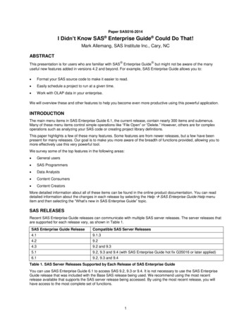
A Hardware Designer's Informal Guide to Zynq UltraScale Version: 1.02020-04-06Do not make the mistake of thinking that any MIO pin can be assigned any function; this is not true.Here’s where Xilinx’s 1200 page document, UG1085 Zynq US Technical Reference Manual becomes crucial,specifically the MIO chart in Chapter 28.Here’s a small clip of this table that actually spans two-pages:Ref: https://www.xilinx.com/support/documentation/user guides/ug1085-zynq-ultrascale-trm.pdf#page 789This chart is interpreted as follows:a. Across the top are the MIO pin assignments. These are not the pin numbers relating to the package itself,these are the MIO pin identifiers. Note: When you create the schematic symbol, Xilinx names the pinsMIO0, MIO1, MIO2, etc., so the pin names align with the table ordinals.b. Down the side are the hard controller interface options. For example, “gem0” refers to the first of four (4)available Gigabit Ethernet MACs, “qspi” refers to the QSPI flash controller, “USB0” refers to the first totwo (2) USB ULPI/PIPE3 Controllers, and so on.How do we use this information to assign MIO pins to our design? We have to go back to our Requirements,understand which of the PS hard controllers we are going to leverage, and then assign them appropriately to MIOpins, without overlap! When I say, “without overlap” here’s what I mean: See how in the chart gem2 and usb0 caneach only be assigned to PS MIO[63:52]? This means that I have to pick one function or the other to use those pins– obviously they both can’t be assigned to those pins at the same time. Then, to meet the rest of yourrequirements, you go through and assign hard controllers without overlap. If you don’t fill up your MIO with hardcontroller needs, unused pins can generally be leveraged as general purpose IO, but keep the function simple,because remember at this point software will have to interact directly with that GPIO pin. Once my MIOassignment is complete, I always, always, always enter the assignment into the Xilinx tools to ensure I don’t haveany conflicts (remember, the ‘M’ in ‘MIO’ refers to a series of multiplexers that connect the hard controllers to theIO pin itself, so there is a chance that your assignment may leave the tools without a way to connect the controllerthrough the layers of multiplexers to the IO pin).WarningAlways verify your MIO pinout using the Xilinx tools. Not all combinations will work!Confidential9
A Hardware Designer's Informal Guide to Zynq UltraScale Version: 1.02020-04-06The next level of complexity, and perhaps the trickiest to ensure you get right, is understanding what the numberswithin the function mean and why more configurable interfaces sometimes have these pins out of order.First, we will look at the qspi controller assignment, as it is an out of order example, then we will look at the gem0controller as it is more straightforward.Starting with qspi, here’s a close-in clip from the main MIO assignment table:As per the table, Xilinx is instructing you to connect MIO[0] to “4”, MIO[1] to “1”, MIO[2]to “2”, MIO[3] to “3”,MIO[4] to “0”, and so on. What do these seemingly random assignments mean? To understand you have to goback to that huge Technical Reference Manual and flip to the Chapter that describes the QSPI Controller (Chapter24), and you will find the table below that holds the key to decoding the main MIO first table. Let’s decode it.Ref: https://www.xilinx.com/support/documentation/user guides/ug1085-zynq-ultrascale-trm.pdf#page 698QSPI is typically implemented in 4-bit data mode, so we’ll discuss that implementation, which means we canignore Quad-SPI1 (upper) and focus on Quad-SPI0 (lower). QSPI is relatively simple and consists of: Chip Select,Clock, and data I/O[3:0].From the table, we uncover the following mapping of ordinals:Chip Select 5, Clock 0, I/O 0 4, I/O 1 1, I/O 2 2, I/O 3 3Now remember back to the master MIO table (the big one), and we now see that the defined ordinals from theQSPI Controller Chapter map to the ordinals in the MIO table.Confidential10
A Hardware Designer's Informal Guide to Zynq UltraScale Version: 1.02020-04-06Which allows us to complete the physical assignment mapping:Chip Select 5 maps to MIO[5]Clock 0 maps to MIO[4]I/O 0 4 maps to MIO[0]I/O 1 1 maps to MIO[1]I/O 2 2 maps to MIO[2]I/O 3 3 maps to MIO[3]Let’s do this two-stage mapping again, but this time with the more straightforward gem0 controller:Start with the main MIO table:Then look for the mapping on the IO table within Chapter 34, GEM Ethernet:Ref: https://www.xilinx.com/support/documentation/user guides/ug1085-zynq-ultrascale-trm.pdf#page 1032Confidential11
A Hardware Designer's Informal Guide to Zynq UltraScale Version: 1.02020-04-06Note that unlike the qspi0 table, the gem0 table does not just show an ordinal that needs mapping, it shows theactual MIO pin identifier. So, we can more easily come to our conclusion:TX CLK 26 maps to MIO[26]TX CTL 31 maps to MIO[31]TX DATA0 27 maps to MIO[27]TX DATA1 28 maps to MIO[28]TX DATA2 29 maps to MIO[29]TX DATA3 30 maps to MIO[30]RX CLK 32 maps to MIO[32]RX CTL 37 maps to MIO[37]RX DATA0 33 maps to MIO[33]RX DATA1 34 maps to MIO[34]RX DATA2 35 maps to MIO[35]RX DATA3 36 maps to MIO[36]It is always important to look at the MIO table, and then understand the actual MIO mapping that is well definedwithin the Chapter related to that desired controller. As we have seen, sometimes we need to map ordinals backto the original table and sometimes the MIO pins map directly. Once you have done this a couple times, it issimple enough – just don’t skimp on the details – understand what the detail within the Controller Chapter istelling you.WarningAlways refer to both the MIO table and the actual Chapter that defines the use and IO of that hard controller!2.3PS MIO Bank VoltageJust like their FPGAs, Xilinx has made the MIO bank voltage configurable. As discussed, there are three (3) MIObanks: Bank 500, 501, and 502. The voltage levels at which these banks operate are defined by the voltage appliedto the VCCO PSIO[0:2] pins. More succinctly put:The MIO within Bank 500 will operate at the voltage level provided to VCCO PSIO0The MIO within Bank 500 will operate at the voltage level provided to VCCO PSIO1The MIO within Bank 500 will operate at the voltage level provided to VCCO PSIO2Now, unlike the FPGAs, there are only three (3) voltage options supported: 1.8V, 2.5V, and 3.3V.Ref: https://www.xilinx.com/support/documentation/data sheets/ds925-zynq-ultrascale-plus.pdf#page 18As usual, the voltage you select for each bank is determined by the devices that are interfacing to that bank. Notethat unlike FPGAs, the MIO within that bank can only operate with the exact voltage applied to that bank. So, nowyou not only have to be aware of the MIO hard controller assignment, but also that all functions assigned to thatbank must operate at the same voltage.2.4ConfidentialExtended Multiplexed IO (EMIO)12
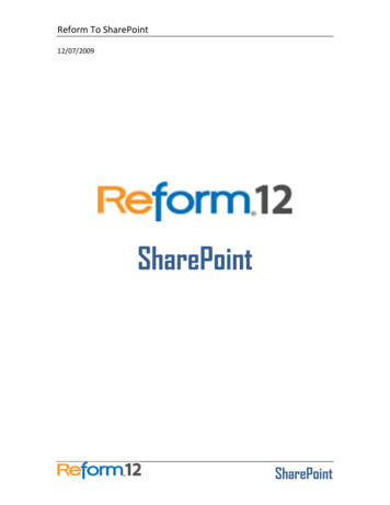
A Hardware Designer's Informal Guide to Zynq UltraScale Version: 1.02020-04-06Xilinx makes FPGAs, FPGAs can do almost anything, so why not add crazy amounts of flexibility to the MPSoC aswell, right? That’s exactly what Xilinx did with their EMIO capability. As I mentioned before, the MIO consists of atotal of 78 pins, and there are a plethora of hard controllers with the PS. In fact, there are more hard controllersthan there are MIO pins to break them out. EMIO is a solution to this problem. EMIO technology enables you tobridge PS-based hard controllers to the PL (i.e. typically the FPGA pins). If you are going to do this, it is critical thatyou run your planned connectivity through the Xilinx tools, as there are a lot of considerations and limitations(operating speed, protocol types, etc.) associated with EMIO. The following Xilinx table summarizes some of theselimitations.Take special note of the “No” in the EMIO Access column.WarningAlways verify your EMIO pinout using the Xilinx tools. Not all combinations will work! And there may be limitationsthat your application cannot tolerate.Ref: https://www.xilinx.com/support/documentation/user guides/ug1085-zynq-ultrascale-trm.pdf#page 482.5Bank 503Bank 503 houses the command and control pins of for the Zynq US . Like the MIO, Bank 503 architecture andfunctionality is identical (excluding pin numbers of course) on every Zynq device. Bank 503 is home to thefollowing pins.VCCO PSIO3: The bank voltage that will determine the signaling level of the Bank 503 pins. Like the MIOVCCO PSIO pins, this voltage can be 1.8, 2.5, or 3.3V.PS DONE: Indicates the PL configuration is complete.Confidential13
A Hardware Designer's Informal Guide to Zynq UltraScale Version: 1.02020-04-06PS ERROR STATUS: Asserted for accidental loss of power, a hardware error, or an exception in the PMU.PS POR B: Power On Reset. This is a hard reset that re-starts both the Low Power Domain (LPD) and the FullPower Domain (FPD).PS REF CLK: PS System’s Reference ClockPS SRST B: System Reset. This is a little less hard that PS POR B as there are several registers that are unaffected(see reference below). This is usually connected to the debugging tool (e.g. JTAG connector).PS JTAG TCK/TDI/TDO/TMS: JTAG Connection.PS MODE[3:0]: The “Mode Pins” are sampled on the rising edge of PS POR B and determine the Primary BootMethod (e.g. QSPI, SD, NAND, etc.).PS ERROR OUT: Asserted for accidental loss of power, a hardware error, or an exception in the PMU.PS INIT B: Indicates that the PL is initialized after a power-on reset.PS PROG B: PL Configuration Reset. Similar to the usual FPGA configuration PROG B pin.2.6Other Dedicated PinsThe following other dedicated pins are worth a quick discussion.B0 PUDC B: Enables weak pull-ups on all SelectIO pins during configuration. Referenced to VCCAUX. These can beused if the Zynq US is interfacing to other ‘less-smart’ components that benefit from a defined state. I don’ttypically use this function as I prefer to externally control things, so I don’t have to worry about pull-up strengthand timing considerations.DXP/N: Internal temperature sensing diode pins. P is the Anode; N is the Cathode. Although SYSMON gives yousimilar capabilities, SYSMON may not always be available, so you may connect this to your thermal monitoringsolution. For example, perhaps your thermal monitoring solution observes the temperature of the Zynq US toeither adjust fan speed or to completely shut down the system if the Zynq US temperature exceeds a specifiedthreshold. In this case, you would typically shutdown the Zynq US (SYSMON no longer available), and thenmonitor the DXP/DXN until the temperature returns to acceptable level before re-enabling the system. It’scomforting having a completely hardware-based thermal strategy.VCC PSADC/GND PSADC: PS System Monitor supply voltage and ground reference.POR OVERRIDE: Sets the PL Power-On Delay Time. Logic 0 is the recommended, default setting. Xilinx explains:“Reduces TPOR time (from power up to INIT B rise) as specified in data sheet. Connect directly to VCCINT for ashorter TPOR time if required and if supported by the power-up timing of the configuration data source. Connectto GND for standard longer POR delay.CAUTION! Do not allow this pin to float before and during configuration. This pin must be tied to V CCINT or GND.”Confidential14
A Hardware Designer's Informal Guide to Zynq UltraScale Version: 1.02020-04-06Ref: https://www.xilinx.com/support/documentation/user guides/ug570-ultrascale-configuration.pdf#page 30PS PADI/PADO: Crystal connection for internal Real Time Clock.VCCADC, GNDADC, VP/N: VCCADC is the voltage used by the internal analog PL System Monitor function. It isreferenced to GNDADC. VP/N are differential inputs, used like inputs to an ADC, connected to the PL SystemMonitor function.VCC PSBATT: PS RTC and Battery Backed-up RAM (BBRAM) Battery Voltage. Typical range: 1.2 to 1.5V. Note that ifyou require Secure Configuration, the key is stored in BBRAM.Ref: cation fVREFP/N: Externally applied PL SYSMON Reference voltage. VREFP receives a 1.25V (typical) supply and VREFN isthe ground reference (this should be filtered from GNDADC). As these are high-impedance inputs, the 1.25V istypically generated from a simple voltage reference. Alternatively, if accuracy is less important than cost or realestate, the internal reference can be utilized, in which case both VREFP and VREFN are connected to GNDADC.Ref: https://www.xilinx.com/support/documentation/user guides/ug580-ultrascale-sysmon.pdf#page 95Warning!Be diligent to ensure that you are referencing the SYSMON analog voltage supplies, references, and signals, to thecorrect ground reference, using the appropriate filtering.2.7PS and PL System MonitorThe Zynq US device contains a PS and PL System Monitor (referred to as PS and PL SYSMON). The SYSMON canmonitor and report certain internal voltage levels and temperatures, in addition, the internal ADCs can be pinnedout to measure external analog signals. There are differences between PS and PL SYSMON. Refer to the attachedXilinx
A Hardware Designer's Informal Guide to Zynq UltraScale Version: 1.0 2020-04-06 1 Introduction After delivering more than twenty (20) Zynq UltraScale (Zynq US ) designs last year, Fidus can truly say that they are expert implementers of the latest Multi-Processor System On-a-Chip (MPSoC; pronounced em-pee-sok) technology from Xilinx .