Transcription
Altium Designer GuideBeginning & Intermediate VersionGlenn Merciermercierg@unlv.nevada.eduResearch Engineer, TBE-B311University of Las Vegas, Nevada
Part 1: Beginning Guide This guide is a beginner’s guide to PCBdesign using Altium Designer and isgeared towards the following individuals: Possess ample theoretical electronicsknowledge Has little or no PCB design experience Has little or no Altium Designer experience
Beginning GuideBefore proceeding to the actual softwaretutorial, It is important to understandwhen it is absolutely necessary to use aPCB rather than design with abreadboard Most students have a reluctance tolearning new software and spendingmoney for something they could possiblybuild on a breadboard.
Breadboard vs. PCBFor many electronic designs, one has achoice to build a circuit on either abreadboard or on a printed circuit board. Most students have a certain comfortzone working with breadboards, but therecomes a time when the complexity of theproject or the physical requirementsrequires electronic design through CAD(computer aided design).
Breadboard AdvantagesVery quick to prototype using standardcomponents Can easily make changes to schematic orthe functional working of the circuit Easy to connect to electronic equipmentsuch as function generator, oscilloscope,power supplies, etc.
Breadboard DisadvantagesUnprofessional appearance Difficult to troubleshoot due to humanerror and poor connections Works very poorly for high speed design Difficult to modify complex SMDcomponents for prototyping Excessive capacitance Difficult to replicate
Printed Circuit Board AdvantagesProfessional appearance Repeatable and controllable strayinductance and capacitance Can handle most power requirements Can make very compact Excellent high speed capabilities Easy to assemble and replicate
Printed Circuit Board Disadvantages Increased design timeDrastically increased schematic-to-finishedproduct timeframeDevelopment CostDifficult to modify once board is fabricatedMust learn at least a basic form of CAD softwareQuality of PCB can be affected by limitedknowledge of software packageCapabilities vary greatly with different softwarepackages.High end CAD software is very expensive
Required PCB Design Small Packages,such as a BGA,MLF, QFP arepracticallyimpossible toprototype on abreadboard dueto their smallsize and MUSTbe designed on DE/ MCROBGA.GIF
Required PCB DesignJust dealing with the sheer number of pinson modern practical designs required aPCB. It is common to see single componentscontaining up to 1,500 pins High speed design cannot be performedusing traditional prototyping methods
Altium DesignerThis is based off the current version of Altium Designer,6.9.0.12759 The Altium Designer Suite contains many unified features such as: FPGA schematic designVHDL/Verilog compilersC/ASM compilersScriptingSimulation2D Field SolverSimulation EngineLibrary ManagementDatabase and advanced query languageCAM display managementSchematic CapturePCB Layout
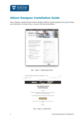
System Requirements
Getting Started Start the software byclickingSTARTPROGRAMSALTIUM DESIGNERAltium Designer 6 Create a start bar shortcutif you plan on using thesoftware a lot. (shown onright)
Project File Project files are like a container for your project.There are many different things you will need foreven a basic project, such as: PCB Footprint librariesSchematic librariesSchematic documentsPCB documentsScriptsCAM filesSettingsGenerated reportsGenerated filesVersion Control featuresEtc.
Creating a Project When thesoftware starts,follow themenu sequencein the image tocreate a new‘PCB Project’ Many peopleskip this stepand just createa schematic file.This a hugemistake!Absolutelyeverything inAltiumDesigner isbased onproject files
Project NameWe need to save our project and rename the project to somethingmore meaningful. Right click on PCB Project.prjPCB and save the project as‘PROJECT- EE495’ to a new folder (preferably on a flash drive)called ‘EE495 Project’ inside a root folder called ‘EE495 Altium’ EX:F:\EE495 Altium\EE495 Project\PROJECT-EE495.prjPCB Inside this folder, we will place all relevant project data
OrganizationIt is useful to place all project information inside this folder. Inside this root folder, create subfolders called ‘CODE’ and‘DATASHEETS’ Organization and centralization is also important for backing up allyour data properly, version control, and copying project data to aCD for all finished projects (which you should do for futurereference)
(Group) Quiz Project #1 For the first quiz project, we are going to createa schematic that will contain: Atmega8 - Atmel Microcontroller , 16 MHz, QFP USB-B Connector FT232 USB- UART interface chip , TSSOP28 2x5 Programming Input Header (0.1” Pitch) SMD (Surface Mount Device) LEDs , 0805 SizeThis project contains all the necessary parts to create aPCB that can communicate directly with a computerthrough a USB (Male B- Male A) Cable. You are encouraged to actually build this PCB as aninexpensive, functional development board.This project is to be finished by next Wednesday (5/28)with a possible in-class portion
Adding a Schematic Drawing Follow the menu sequence shown tocreate a new schematic. This willautomatically be added to the projecttree we created.
Schematic EntryThe ‘sheet1’ schematic document is now addedto the project tree as shown below. Rename this file to something with a moremeaningful name such as ‘Main’. There are manytimes when you will have multiple schematicentries and it helps to have a descriptive name Any open project files will appear in the menuarea above where the blank schematic pageappears.
Libraries Similar to a real laboratory, to build a designfrom a schematic you must first add realparts to the project. For this, we must add what are called‘libraries’ to our project. Libraries containvital information about the parts we aregoing to add. Once libraries are added to the project, anycomponent inside that library can be freelyinserted into your design.
Types of Libraries There are three main types of libraries for PCBdesign: Schematic Library- Contains schematic drawings of parts,when we look at a schematic, we are looking at a collectionof schematic parts PCB Footprint Library- This contains the physical dimensionsof a real component. This information is readily available indatasheets. Integrated Library- These are the most useful librariesbecause they combine a physical part (footprint) with aschematic drawing.
Libraries Libraries are located in the folder: C:\Program Files\Altium Designer 6\Library Updated libraries are available online at Designer6libraries/Altium has since changed some of theirlibrary files, I have included a ZIP file onthe course website with library files we’llbe using. Download and unzip the file into the‘library’ folder in your project directory
Libraries Copy the following Libraries to a folder called ‘Libraries’ in your Custom Altiumfolder:Integrated Libraries (*.IntLib) Atmel Microcontroller 8-bit AVRMiscellaneous ConnectorsMiscellaneous DevicesNSC Operational AmplifierON Semi Operational AmplifierSchematic Libraries (*.SchLib) none Footprint Libraries (*.PcbLib) Chip Capacitor – 2 ContactsChip Diode – 2 ContactsChip Inductor – 2 ContactsChip Resistor – 2 ContactsCrystal OscillatorMiscellaneous Connector PCBMiscellaneous Devices PCBMiscellaneous DevicesMiscellaneousNOTE: When you create your own schematic and footprint libraries, you shouldplace them in the same library directory in your project folder
Adding Libraries To A Project We have organized all the libraries in afolder, now we need to add these to theprojectFollow the following prompt to addlibraries to the project
Adding Libraries There are two methods of adding libraries Project Libraries- Libraries available only for the scope of this project Installed libraries – Libraries available to ALL projects by default. These do not showup in the project tree. The Search Path modifies the search location when searching for parts.
Adding Libraries We want to make these libraries projectspecific only instead of global availability withthe ‘Installed’ tabMake sure the ‘Project’ tab is selected, and addall libraries from your project library folder
Project Hierarchy By expanding the ‘ ’next to libraries, youshould see a list of allthe project libraries.Make sure you have allthese librariesinstalled beforecontinuing. Notice how theproject tree separatessource documents andlibraries automatically
Open, Saved, Unsaved Files Open files are indicatedwith a ‘white paper’ Open modified andunsaved files areindicated with a ‘redpaper’ Example: The Project fileitself has been modified.Closed files havenothing in the column Example: Main.SchDocExample: The AtmelMicrocontroller libraryAll open files areaccessible by clicking onthem in the project tree,or in the top bar in awindows- taskbar typewindow
Project Documentation We can’t createa schematicwithout knowingmore detailsabout the partswe’ll be using. Obtain the FTDIFT232R UARTIC Datasheet Rename the filesomething lesscryptic such asFT232 USB.pdf
Project Documentation Specifications are often given or required for components, You should check anddouble check each meets the project specifications. Atmega8 Microcontroller, QFP Package, 16 MHz, ROHS CompliantMouser P/N:556-ATMEGA8-16AUSave as ‘Atmega8 QFP Atmel Microcontroller.pdf’ USB-B (Female/Socket) , ROHS Compliant, Right Angle MountMouser P/N:806-KUSBX-BS1N-B30Save datasheet as ‘USB-B Connector’ SMD LEDs (0805), ROHS CompliantMouser P/N: 638-172BHC-AN1P23T2x5 Box Header (Prog. Connector), Gold Plated, ROHS Compliant, Pitch 0.1”Mouser P/N:649-66506-066LFSave datasheet as ‘2x5 Box Header.pdf’
Chip Sizing Information ‘Chip’ components are devices that come in small rectangles The 0805 specification for the LED are actually dimensions of the chip componentitself (Size Code). Split up the numbers to 08 The Length of the chip diode is 0.08” 80 mils The Width of the chip diode is 0.05” 50 mils Therefore, the larger the numbers, the larger the chip device: Larger chip sizes can handle more power Smaller chip size can handle higher frequencies (ideally)05, These are the dimensions in inches
Chip Sizing Information 1) Tantalum Capacitor (A-Case) 2) Tantalum Capacitor (D-Case) 3 & 4) Electrolytic Capacitor 5) 0805 Ceramic Capacitor 6) 1206 Ceramic Capacitor 7) 1210 Ceramic (Same length, but wider) ¼ Watt through-hole resistorgiven as size reference(Same as in our aps.jpg
Chip Sizing Information 1) 1218 (1 Watt) 2) 1206 (1/4 Watt) 3) 0805 (1/8 Watt) 4) Potentiometer (Bottom & Top) ¼ Watt through-hole resistorgiven as size reference(Same as in our esistor.jpg
Chip Sizing Information 1) 20 Pin DIP Package 2) SOIC20, Wide 3) SOIC8, W/Power Tab 4) SOIC8, Standard 5) SSOP20 ¼ Watt through-hole resistorgiven as size reference(Same as in our c.jpg
Placing PartsWe have now added all the necessarylibraries for the project, now we need todraw the schematic. Follow the menu sequence below to placea part
Placing Parts After clicking ‘placepart’ from theprevious screen, youwill have an option toplace from standardlibraries or databaselibraries. Keep this onstandard libraries Click the button tothe right of the‘History’ button tobring up a list ofavailable libraries.
Creating a Schematic At the top of the screen, there is a dropdown box which lists available schematic and integratedlibraries (but not PCB footprint libraries). For the highlighted library, in this case MiscellaneousDevices, there will be a list of the parts inside that library in the bottom left.
Creating a Schematic Select the AtmelLibrary and navigatedown to Atmega8.Notice there aremany options for thesame chip. This isbecause although thedevice is the same,there are manydifferent ‘packages’that this chip comesin. NOTE: The Atmega8costs about 3.50
Creating a Schematic Add the ATmega8-16ACLooking at the datasheet for the ATmega8, we can see exactly what the -16AI stands for. Supports up to a 16 Mhz clockCommercial grade fabrication (Temperature ranges from 0C to 70C
Creating a Schematic Here are the threecommon packages forthe ATmega8microcontroller. These are scaled relativeto each other with theclose to the samefunctionality with eachpackage. NOTE: Why does theQFP package have 4more pins than the DIPpackage?
Creating a Schematic We were given constraints with the assignment ofthis project. Sometimes constraints are based on: Economics, Size, Power handling, ability to assemble the part, etc. For the microcontroller, we were told it mustfunction with a clock rate of 16 MHz, and must havea QFP Package It is crucial to take note of all constraints BEFOREentering the schematic and/or pcb layout. It is aHUGE waste of time to design around a part thatdoesn’t meet the specifications.
Creating a Schematic Looking again at the ordering information available in the datasheet, we knowthat: The Chip must be able to work with a 16 MHz clock, we can eliminate all 8MHz ratedmicrocontrollers The DIP package is 28 pins, we can eliminate any package that has a ‘28’ in thepackage information The 32M1 refer to the MLF packaging, we can eliminate all those items This leaves us with a decision to choose between commercial rated or industrialrated temperature ranges, Either the ending in -16AC, -16AI, -16AU are acceptable
Creating a Schematic Usually the industrial rated components are more costly than the commercialrated components, so we will choose the Atmega8-16AC QUESTION: A temperature rating doesn’t affect the footprint or simulationof the device, is there a reason we can’t/shouldn’t just choose any of the threepossible options ?
Creating a Schematic Notice to the right, there is the schematic drawing and associated pinoutof the device, beneath that is a drawing of the PCB Footprint (this shouldmatch what you expect from the datasheet) The bottom shows all footprints associated with the part Why do you think there are three different footprints for a QFP32 ?
Creating a Schematic Many vendor supplied integrated libraries contain much more than just aschematic drawing and PCB footprint Shown below is a rendering of a 3D Image of the chip. Altium has an option toview the PCB in 3D, and this image will represent the Atmega8 in the 3Drendering Also included are SPICE files and/or IBIS files (more on this later)
Creating a Schematic Place the Atmega8 into the schematic drawing You can always move the location later What function does pin 20 perform ?
Zooming In and Out You can’t see the function of pin 20 because the image is zoomed out.To Zoom In/Out Wheel Mouse and Control Key Page Up/Page Down KeyTo Pan Left/Right/Up/Down Wheel Mouse and Shift Key Left/Right/Up/Down Arrow (Small Pan) Shift Key and Left/Right/Up/Down Arrow (Larger Pan)
Pin Functions Pins can be setup for the following functions: Input, Output, I/O Open Collector, Passive, HiZ, Emitter, PowerDepending on how the pin is set, will determine how the DRC (Design Rule Check)Interprets the Pin and what connections are allowed
Add the USB-B Connector It seemed obvious which library contained the Atmel Atmega8, butnow we need to add a USB-B connector. An easier method than searching each component and each library isto search the libraries. Click the ‘Find’ button to the right of the library selection(It doesn’t matter which library is selected/active)
Add the USB-B Connector Type in the keywordyou are looking for We are looking for aUSB-B connector, Fornow let’s just searchfor ‘USB’ and narrowdown the search afterthat. NOTE: Usingwildcards * before andafter allow for wordssuch as xxxUSBxxxto be recognized.
Add the USB-B Connector The search can take awhile depending onhow many librariesyou are searchingthrough. We are searchingthrough only thelibraries we added tothe project, so itshould happen veryquickly. The result of thissearch came backnegative, That meansthere are no USBitems in any of ourproject libraries. Click the ‘Search’ tabin the top right corner
Add the USB-B Connector Change the scope ofthe search fromavailable libraries(available to theproject) to ALLlibraries in the path. The path willautomatically beentered for the defaultlibrary location inAltium * make sure ‘includesubdirectories’ isticked. Click the searchbutton
Add the USB-B Connector USB is a very common term, so very quickly the list fills up Expanding the box to read the description helps with identifying what eachpart is (in case names such as ‘1-353576-1’ mean nothing to you) We are looking for a SINGLE Through Hole, Right Angle, USB-BReceptacle socket, which is located at the 8th row down
Add the USB-B Connector Select the 1-1470156-1and click OK You will get a messagestating that the library isnot available to theproject, but Altium iswilling to install it for you,click yes Click ‘OK’ again to addthe part
Add the USB-B Connector The library AMP Serial Bus is added automatically to the ‘Installed’ libraries,NOT the project libraries This action DOES NOT MOVE ANY LIBRARIES PHYSICAL LOCATION For ease of future design, it is a good idea to move libraries added by thismethod to your ever-growing list of libraries You can do this by copying the AMP Serial Bus USB from the path given inthe ‘available libraries’ belowC:\Program Files\Altium Designer 6\Library\Ampto your custom library in your flash driveX:\EE495 Altium\EE495 Project\Altium Libraries
Add the USB-B Connector AMP makes several different libraries, so be sure to copy the correct one!
Rotating Parts The easiest wayto rotate parts isto select the itemand hold the leftmouse buttondown, and tapthe space button,this will rotate 90degrees each tap. Another methodis to double clickthe componentto open up thecomponentpropertieswindow, and inthe bottom leftcorner you canset theorientation NOTE: the‘mirrored’ tabwill flip thecomponentabout its axis
Component Properties In the top left corner of thecomponent properties, you can setcomments, descriptions, designatorvalues and library link information NOTE: Unique ID is a unique valuewhich links the schematic part withthe PCB document. In the bottom left corner, you can setgraphical properties such asorientation, mirrored, locked (stuckin schematic) The ‘Edit Pins’ button will allow youto reassign pins, pin functions, and pinnumbers. This should only be used ifyou are absolutely positive you knowwhat you are doing!!
Component Properties In the top right corner ofcomponent properties of astandard component will containinformation such as publishingdate, termination length, URL’s,drill sizes, etc. NOTE: You can add your owncustom fields (such as orderinginformation, ordering partnumbers, etc.) NOTE:You can also add acustom PCB rule to thecomponent while you are still inschematic capture mode The bottom right cornercontains model information forthe component, such asfootprint model information andsignal integrity models.
Component Properties Mirror theUSB-Bconnectorand orientthe parts sothey matchthe diagramto the right.
Programming Header Add a part from the Miscellaneous Connectors library called ‘Header5x2’ Make sure to use caution when selecting parts. If you accidentally add‘Header 5x2a’ they make look the same, but look at the numberingsystem of the pins. Always make sure the numbering method is the sameas you expect it to be.
FTDI Chip- FT232 (TSSOP28) A quick search forthe FT232 chip wewill be using givesthe following result Although there arethree matches forthe FT232, We areactually looking forthe FT232RL as wewill see on the nextslide
FTDI Chip- FT232 (TSSOP28) Like all aspects ofPCB layout, youmust pay attentionto every detail oneverything. The datasheetstates that theFT232RL is a 28-pinSSOP package. Since this footprintis not available, wemust create thepart in a customlibrary
FTDI Chip- FT232 (TSSOP28) Follow the menusequence shown tothe right to create anew PCB library. This library willhouse ALL of yourcomponents
FTDI Chip- FT232 (TSSOP28) The new library isautomatically added tothe project. Right click and click‘save as’ and renamethe library to a moreappropriate name:EE495 and save it in thedirectory with the restof your libraries
FTDI Chip- FT232 (TSSOP28) Notice the small tabs inthe bottom left corner. Double click the newPCB library youcreated to open it, andclick on the one titled‘PCB Library’ to workinside that library.
FTDI Chip- FT232 (TSSOP28) With the PCB Librarytab selected, we can seethat there is only onecomponent inside ourlibrary calledPCBCOMPONENT 1
FTDI Chip- FT232 (TSSOP28) From inside your PCB library, click TOOLS IPC Footprint Wizardto open the IPC Footprint Wizard. This will help you easily create the footprint for the device You will see why it is so important and helpful to have standardswhen it comes to documentation, naming conventions, etc
FTDI Chip- FT232 (TSSOP28) The first step is selecting what type of part it is. They don’tspecifically have SSOP, but SSOP is just a modified version of theSOP so select that There is a diagram of what the chip looks like to the right NOTE: check the note on the bottom of the wizard: All wizardmeasurements must be entered as metric (mm) units
FTDI Chip- FT232 (TSSOP28) At first this might seem a bit daunting and intimidating, but when youpull up the datasheet to find the values, you will see that the graphicsand naming convention matches what we must entered
FTDI Chip- FT232 (TSSOP28) The first entry is for width range. The datasheet gives a width rangeof 7.80 /- 0.40mm (Min width 7.4mm, Max 8.2mm)
FTDI Chip- FT232 (TSSOP28) The max height of the chip (A) is2.00mm Enter this in for maximum height Question: Why would the heightof the chip matter ?
FTDI Chip- FT232 (TSSOP28) Fill out the rest of the values, you should get the numbers below NOTE: Watch as you enter values, the graphic on the right willdynamically change
FTDI Chip- FT232 (TSSOP28) Accept the automatically entered values for the next few slides untilyou get to the slide below Uncheck the ‘use suggested values’ and change the name to FT232RL Click ‘Finish’ and the part will be added to your library
FTDI Chip- FT232 (TSSOP28) Your library willautomatically openwith your new partincluded. Notice how thereare two yellowdots , those are ‘pin1 indicators’ sothe board isassembled properly You can now beconfident that theFT232RL chip willfit on this footprint
FTDI Chip- FT232 (TSSOP28) Click the ‘Projects’ tab on thebottom left to return back tothe project file hierarchy Since a PCB footprint is uselessas far as a schematic isconcerned, we must create aschematic drawing and link thedrawing with the footprint wecreated
FTDI Chip- FT232 (TSSOP28) Keep in mind thatwe cannot keep theschematic drawingof the FT232 andchange only thefootprint becausesometimes pins areadded, removed, orare different. Shown to the rightis the pinout of thedevice obtainedfrom the datasheet
Creating a Schematic Part Create a Schematiclibrary like wecreated a PCBfootprint library Rename the libraryto EE495, and savein the samedirectory as therest of yourlibraries. Double click theschematic library toopen the library,and then view thelibrary by clickingthe ‘SCH Library’tab in the bottomleft of the screen
Creating a Schematic Part The large portion of the screen is for creating your schematic drawing, thetop left part contains all the parts in the library, the towards the bottom leftis the pins and associated function/name
Creating a Schematic Part Double click the component and enter the values as shown below
Creating a Schematic Part Your component should have a descriptive component name anddescription such as the one below Click the ruler tab to see the dropdown listas shown in the right. This is the main icon we’llBe using in creating the schematic drawing
Creating a Schematic Part Place a rectangle and draw it so it looks like below(Size doesn’t matter)
Creating a Schematic Part Click the ‘place pin’ and place 28 pins around the rectanglelike below Click and drag the rectangle to the proper size
Creating a Schematic Part Double click Pin 1 and changedisplay name to TXD, Change electrical type toOUTPUT
Creating a Schematic Part Sometimes the datasheetwill explicitly give thefunction of the pin, this is anadded bonus and not usuallygiven You must usually define thepin type from reading thedescription of what the pindoes Defining pin types is not anecessity, and things maywork fine without definingthem properly, but youshould usually add the pinfunction to allow the DRCto catch your errors.
Creating a Schematic Part There are usually typical applications schematics which will helpyou properly use the device. You should always read each and every pin description to see ifyou need to add functionality, but it is always a good starting pointto use the typical application sheet
Creating a Schematic Part Usually these typical application notes have corresponding notesassociated with it that you should consider. The following rules for this device are a combination of rules forthe USB standard, and for the FT232 These notes should be regarded as bible, written by people whounderstand and have tested their product to death.
Creating a Schematic Part Now that we have verified that the pins all match the ones in thedatasheet (with the correct pin numbers!) we can move pinsaround and make it look more like the application schematic given This usually allows for a cleaner looking schematic drawing andmuch easier to reference the datasheet.
Creating a Schematic Part Now that we have verifiedthat the pins all match theones in the datasheet (withthe correct pin numbers!) wecan move pins around andmake it look more like theapplication schematic given This usually allows for acleaner looking schematicdrawing and much easier toreference the datasheet. NOTE: You can also hide pinsfrom the schematicdocument. Double click onthe pin and check ‘hide’
Creating a Schematic Part Now we needto associate thePCB Footprintwe createdwith theschematicdrawing Click the ‘addfootprint at thebottom of thepage Click ‘browse’in the ‘footprintmodel’ section
Creating a Schematic Part Select your EE495 Library from the dropdown list There is only one part inside your custom EE495 library, so thechoice is easy. Select your part and click ‘OK’
Creating a Schematic Part In your schematic library, youshould now see the footprintyou created along with theschematic drawing you made Finally the part is complete!! NOTE: This gets much fasteras you do it more, but you cansee the value of the large listof integrated libraries includedwith Altium
Creating a Schematic Part One last check is to look atthe left side of the screen. Thefirst three columns in this caseall refer to data you enteredwhen creating the schematicdocument The last column (FT232RL) isthe name that you gave thePCB Footprint Check and compare that pin 1on the schematic is linked topin 1 on the PCB footprint Repeat for the rest. Ifsomething doesn’t match,something went wrong!!
Save the Project Now is a good time to savethe project and all thechanges you made. Follow the menu sequenceto the right to save theproject
Insert The FTDI Chip Select your EE495 library, and place the only component in yourlibrary (so far).You should see the schematic drawing and also thePCB footprint. If not something is wrong
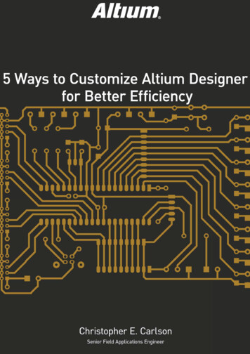
Insert The FTDI Chip Notice how the rotated and mirrored USB-B connector matches upperfectly with the FT232 chip. (D- goes to USBDM, D goes toUSBD ) This did not happen by chance
Current Schematic
Programming Interface We need a devicethat will send ourcompiled HEXcode to themicrocontroller. This type ofdevice is called aprogrammer Sparkfun sellsmany decentprogrammers thatare cheap ( 13)
Programming Interface If you want, youcan see theschematic of theprogrammer, andintegrate it ontoyour developmentboard As you can see,this is a simpledevice whichwould only add afew componentsto your project
Programming Interface The specification for the2x5 header, spaced 0.1”apart perfectly matchesthe connection for theprogrammer. Although you may notknow what these pinsare, we will assign themto the programmerheader
Placing a Connective Wire Find the icon that looks like the one above, andclick it to place a wire, it will be blue in appearanceWARNING!!: Make sure not to use the‘place line’ from the drawing box. Thiswill draw a line that LOOKS like aconnective wire, but a connectionwon’t be made
Placing a Connective Wire Draw wires on the2x5 header as shownon the rightClick the GND andVCC icons from thewiring menu (shownbelow) and make itlook like the diagramto the right
Net Labels A net label is a method of electrically connecting netsof the same nameThis allows a method to make a connection withoutrequiring placing a wireSo what’s wrong with running wires ? It is far moredifficult and more confusing to run wires, especiallywhen routing a large bus.
Net Labels Here is a schematic which is very confusing and would benefit from usingnet labels
Net Labels This is a designthat uses directwires for shortconnections, andnet labels for longconnections. Notice how theschematic looksmore clean andprofessional. NOTE: Even ifdirect wireconnections areused, it’s still agood idea to givethe net a n
Altium Designer This is based off the current version of Altium Designer, 6.9.0.12759 The Altium Designer Suite contains many unified features such as: FPGA schematic design VHDL/Verilog compilers C/ASM compilers Scripting Simulation 2D Field Solver Simulation Engine Library Management Database and advanced query language