Transcription
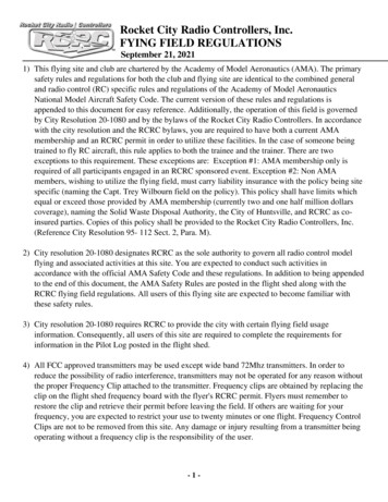
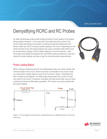
Demystifying RCRC and RC ProbesAn ideal oscilloscope probe would simply provide an exact replica of the signalbeing probed. However, in the real world, the probe becomes a part of thecircuit under test because the probe or probing accessories attached to thedevice under test (DUT) introduce probe loading to the circuit. Depending on theprobe and the circuit, the probe loading may cause unwanted side effects suchas overshooting, ringing, and DC offset problems in the time domain. Learnmore about the difference between RC and RCRC probe architecture, what thismeans for probe loading, and how to get the most accurate measurements.Probe Loading BasicsWhen making measurements with an oscilloscope probe, you want a probe withminimal impact to the circuit. Since the probe is connected to the circuit it actsas a load when it draws signal current from the circuit. Figure 1 illustrates thiswith a simple circuit diagram. An ideal probe would draw zero current or havezero load on the circuit. In practice, all probes will draw some load; and you wanta probe that draws as little load as possible. This means you want a probe withlow probe loading.Figure 1. Circuit diagram showing how a probe becomes an additional load on the circuitunder testFind us at www.keysight.comPage 1
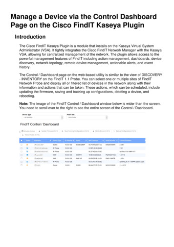
Across the range of frequencies, the probe loading is different based on the resistive, capacitive, andinductive loading effects. Understanding the following 4 types of loading effects shown in Figure 2 willset the stage for understanding the difference between an RC vs. RCRC probe.Figure 2. Typical probe loading profile of an oscilloscope probeResistive LoadingAt DC or low frequency ranges, the primary loading is the probe’s input resistance. Resistive loadingmainly affects the DC parameters like DC amplitude accuracy, DC offset, and bias voltage change. Thisloading can be significant for low-impedance resistive divider type probes like a simple passive probe.When a low-impedance probe is used for probing a circuit with a similar or higher impedance magnitude,a large portion of the current that is flowing through the circuit will now flow into the probe, reducing thevoltage at the point being probed. To avoid resistive loading, a larger input impedance is required.Capacitive LoadingFrom the RC corner frequency to the first LC resonance frequency, the signal’s load is mainly driven bythe capacitive loading, as shown in Figure 2. Capacitive loading increases as the frequency increases.This is because as frequency goes up, the impedance of the probe’s capacitance goes down. Theprobe’s capacitance shunts the high-frequency signals to ground and significantly reduces the probe'sinput impedance as frequency increases. This loading is significant for high-impedance passive probes.It significantly limits the probe’s bandwidth and slows down the edge speed of the signal. Higherbandwidth probes require extremely low input capacitance, usually achieved by special geometries,lower K material/component selection, and good assembly processes.Find us at www.keysight.comPage 2
Inductive LoadingAbove the first resonance and below the second resonance frequency, the signal’s load is mainlyinductive. Inductive loading distorts the signal being measured if the LC resonance is below the probe’sbandwidth. The loading comes from the inductance of the loop created from the probe signal tip to theprobe grounding tip. The magnetic flux creates induced voltage in this loop. This parasitic inductor,together with the resistance and capacitance from the overall circuit, create a typical resonancefrequency at: f 1/(2π LC).If this self-resonance is not damped, it can cause a significant overshoot in the frequency response ofthe probing system and therefore distorts the measured signal. The effect of inductive loading typicallyappears as ringing in the observed waveform on the scope screen. The source of the ringing is the LCcircuit, which comprises the probe’s internal capacitance and the ground lead, and the probe tipinductance. The ground inductance includes the inductance of any jumper wires you have soldered ontothe board or any alligator ground clips you've connected to facilitate probing. In order to minimize theinductive loading effect on your probing, our recommendation is to use as short a ground lead aspossible.Mismatch LoadingMismatch loading is more significant when the frequency is at the range where the wavelength is equalto or less than the cable length (usually above the second resonance frequency). The probing systemshould be viewed as a transmission line instead of a first-order RLC model. The probe impedancetherefore changes over frequency, which is seen as resonances in the frequency response, as shown inFigure 2. The mismatch can occur anywhere from the probe tip to the scopes’ ADC input and causesmultiple reflected waves. The longer the cable, the lower the resonance frequency is. To push theresonance frequency out to a higher frequency range, the amplifier at the probe tip is designed to drivethe cable so that the mismatched signal path from the probe tip to the high-input-impedance amplifier isminimized. This is in part why active probes can have higher bandwidth than passive probes.The Two Dominant Loading Effects for High-Bandwidth, Active ProbesMost high-bandwidth active probes for probing high-speed signals are dominated by two of the probeloading effects in the range specified by the max bandwidth: capacitive and resistive loading. This is aconscious design in probe architecture because high-speed digital designers require high accuracyprobing solutions. When talking about the probe loading effects of these high-bandwidth, differential,active probes, we can summarize their probe loading by describing the two common probearchitectures: RC and RCRC input impedance (see Figure 3).Find us at www.keysight.comPage 3
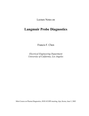
RC architecture (InfiniiMax I/II/RC/Ultra)RCRC architecture (InfiniiMax III/III )Figure 3. Input impedance profile of two common probe architectures: RC and RCRCTake a look at the red trace in Figure 3. At frequencies as low as 10 MHz, you see the inputimpedance is 50 kΩ driven by input R of the probe. It then intersects the 210 fF capacitance of theprobe. That is what we call an RC input impedance profile since it is first dominated by theresistance, then the capacitance of the probe. This is a common input impedance profile for manyoscilloscope probes including Keysight’s InfiniiMax I/II/RC/Ultra probes.Take a look at the blue trace in Figure 3. First, it has a 100 kΩ differential impedance at DC and atvery low frequencies, then it intersects with the 50 nF capacitance of the probe, where it hits the midband impedance. Then over six decades of frequency, it maintains a 1 kΩ differential inputimpedance until it finally intersects the 32 fF capacitance. We call this profile an RCRC architecturesince from low frequencies to high frequencies it’s dominated by the probes’ resistance, thencapacitance, then resistance again, then capacitance again. This is very typical of high bandwidthsuch as the Keysight InfiniiMax III/III probes.Comparing RC and RCRC ProbesKnowing the maximum bandwidth of your probe and the bandwidth of the signals you are trying tomeasure is the first step in understanding which probe will do the best job of accurately capturing yoursignal. An RC probe has the highest impedance (lowest loading and least signal distortion) across thewidest frequency range. But an RCRC probe usually has a higher impedance than the RC probe at boththe very low frequencies and very high frequencies, but it’s midband impedance is usually much lowerthan RC probes.Find us at www.keysight.comPage 4
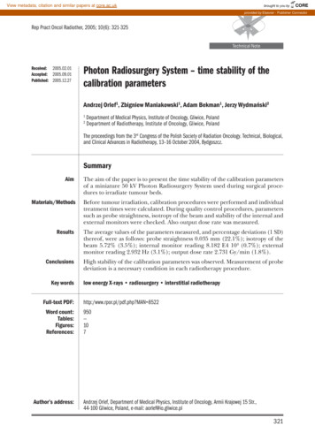
Another consideration when selecting a probe is to consider the source impedance. If you have a signalthat transitions to high impedance modes, such as those signals found in the latest DDR and MIPIstandards, then an RC architecture is best so that the probe loading does not affect the circuit undertest. Generally, RCRC probes do an excellent job of reproducing wave-shapes with fast edge speeds,but may produce effects when trying to measure absolute voltage levels, especially when the sourceimpedance of the target signal is high or if there are long time constants in the signal being probed.RC vs. RCRC In The Time DomainBelow in Figure 4 is a simulated plot of three different probes measuring a step with a 20 psecrisetime in the time domain. The black trace is the Vsource signal before the probe is attached. Thered trace shows how the probe loading can affect the waveform when a Keysight InfiniiMax probe withRC architecture is connected. You can see that the edge has slowed down a bit with a rounded top,which is reducing the rise time and knocking the bandwidth down of the probe point.The blue trace indicates the signal as loaded by a Keysight InfiniiMax probe with RCRC architecture.The magenta trace is another vendor’s probe, but also with RCRC architecture. The blue tracedoesn’t nearly have the rise time degradation, but it does have amplitude degradation. Whathappened is the midband loading of 1 kΩ or 500 Ω per each side of the probe caused the amplitudeto reduce by 5%.Note that the other vendor’s trace may not be exactly comparable because it may have a differenttransfer function and the way the probe is calibrated may be different. But the point here is to note thegeneral trend of the traces for RC vs. RCRC. RC probes generally have less impact on the signalamplitude due to lower input loading at midband ranges but may change the rise time of a fast stepdue to a probe loading effect with higher capacitance. RCRC probes generally have broadbandattenuation, but they preserve the wave shape very well due to high bandwidth and low loading athigh frequency. Note, for all these measurements, we assumed 25 Ω source impedance.Black: a 20 pS 10-90% step with noprobe attached (Vsource)Red: tr 31.1 pS, Keysight InfiniiMaxprobe with RC architectureBlue: tr 20.4 pS, Keysight InfiniiMaxprobe with RCRC architectureMagenta: tr 21.4 pS, other vendor’sprobe with RCRC architectureFigure 4. RCRC vs RC probe comparison in time domainFind us at www.keysight.comPage 5
Selecting the Right Probe Gives You the Right ResultsThere are advantages and disadvantages to RC and RCRC probes, so there is not always one correctchoice. Below are a few examples where we compare the two probe types for specific applications. Youneed to consider what would be best for your own device and application. To assist you, Keysight offersit’s InfiniiMax Probing System with both RC and RCRC probes. The InfiniiMax I/II/RC/Ultra probes rangefrom 1.5 GHz to 25 GHz. The InfiniiMax III/III probes range from 4 GHz to 30 GHz. Check out theInfiniiMax probes and more high-performance probes from Keysight at Infiniium Oscilloscope Probesand Accessories Data Sheet.Example #1: MIPI D-PhyThe MIPI D-phy signal standard provides a flexible high-speed, differential and low-speed, low-powersingle-ended serial interface solution for interconnection between components within mobile andembedded devices. Depending on the application, the D-Phy can transition from 50 Ω HS (high speed)mode to high impedance LP (low power) mode to save power usage (Figure 5). In LP mode, thesignaling is single-ended with a 1.2 V swing operating at a max data rate of 10 Mb/sec. The impedancedriving the bus is typically pulled up or pulled down with a high value resistor, and this interacts withthe RCRC input impedance of the probe, which causes very long time constant effects and anoticeable change in signal amplitude (yellow trace in Figure 5). In this case, the 1 KΩ differential inputimpedance of the RCRC probe introduces probe loading effects, resulting in amplitude change, whilethe higher impedance RC probe does not. Therefore, it is generally not recommended to use an RCRCtype probe for this type of bus. An RC type of probe with high input impedance across the widebandwidth range, such as a Keysight InfiniiMax I/II/RC/Ultra probe, is recommended for this application(blue trace in Figure 5). An RCRC probe would do a better job in measuring high speed signals withlow source impedance, such as a 50 Ω transmission line.Yellow: KeysightInfiniiMax probe withRCRC architectureBlue: KeysightInfiniiMax probe withRC architectureFigure 5. An RC probe is a better choice when probing buses that transition to a “high Z” state, such as thisMIPI D-phy signalFind us at www.keysight.comPage 6
Besides MIPI D-phy there are also more signal standards that use buses that transition to a “high Z”state including the latest DDR and LPDDR standards. When signals have a high impedance, an RCprobe is recommended for the most accurate results.Example #2: Embedded Multi-Media Controller (eMMC)Let’s look at another example – the eMMC (Embedded Multi-Media Controller). The eMMC is amemory card standard used for solid state storage. It puts the MMC components (flash memory pluscontroller) into a small BGA IC package for use with portable consumer products such as mobile andtablet devices.Here in the eMMC circuitry, we are about to measure the Data Strobe line. The driver circuit is drivingthe eMMC circuit load pulled down to ground through a 10 kΩ resistor (Figure 6). The data rate of thesignal is 400 Mbps, which is a slow speed signal for an RCRC probe. The source impedance isindeed very heavy for any probe to deal with. When the Keysight InfiniiMax probe with RCRCarchitecture is used notice that the idle state voltage gets loaded by the probe and the signal level isshifted (Figure 7). However, when the Keysight InfiniiMax probe with RC architecture is used, the idlestate gets down close to zero voltage as was expected (Figure 8). So, in this case, the RC probe isthe better choice for more accurate measurement results.Figure 6. The driver circuit is driving the eMMC circuit load pulled down to ground through a 10 kΩ resistorFind us at www.keysight.comPage 7
Figure 7. The eMMC data strobe line measured with a Keysight InfiniiMax probe with RCRC architectureFigure 8. The eMMC data strobe line measured with a Keysight InfiniiMax probe with RC architectureFind us at www.keysight.comPage 8
ConclusionMost oscilloscope probes have either an RC or RCRC input impedance architecture, and it’s important toknow what your probe has to anticipate its measurement strengths and weaknesses. Be sure to considerprobe loading effects to get the best accuracy possible. Most probe manufacturers provide input loadingmodels so you can understand the probe loading characteristics before you choose a probe. Keysight hasmany different probes optimized for different jobs, check them out in the links below.More InformationFor more information on Keysight’s probing solutions, check out the following: Keysight Probe Resource Center Infiniium Oscilloscope Probes and Accessories Data Sheet InfiniiVision Oscilloscope Probes and Accessories Data Sheet InfiniiMax Ultra Series Probes with RC Architecture Data Sheet InfiniiMax III/III Probes with RCRC Architecture Data SheetLearn more at: www.keysight.comFor more information on Keysight Technologies’ products, applications, or services,please contact your local Keysight office. The complete list is available at:www.keysight.com/find/contactusFind us at www.keysight.comThis information is subject to change without notice. Keysight Technologies, 2015 - 2021, Published in USA, September 13, 2021, 5992-0694ENPage 9
Figure 4. RCRC vs RC probe comparison in time domain Black: a 20 pS 10-90% step with no probe attached (Vsource) Red: tr 31.1 pS, Keysight InfiniiMax probe with RC architecture Blue: tr 20.4 pS, Keysight InfiniiMax probe with RCRC architecture Magenta: tr 21.4 pS, other vendor's probe with RCRC architecture