Transcription
View metadata, citation and similar papers at core.ac.ukbrought to you byCOREprovided by Elsevier - Publisher ConnectorRep Pract Oncol Radiother, 2005; 10(6): 321-325Technical NoteReceived: 2005.02.01Accepted: 2005.09.01Published: 2005.12.27Photon Radiosurgery System – time stability of thecalibration parametersAndrzej Orlef1, Zbigniew Maniakowski1, Adam Bekman1, Jerzy Wydmański212Department of Medical Physics, Institute of Oncology, Gliwice, PolandDepartment of Radiotherapy, Institute of Oncology, Gliwice, PolandThe proceedings from the 3rd Congress of the Polish Society of Radiation Oncology. Technical, Biological,and Clinical Advances in Radiotherapy, 13–16 October 2004, Bydgoszcz.SummaryAimThe aim of the paper is to present the time stability of the calibration parametersof a miniature 50 kV Photon Radiosurgery System used during surgical procedures to irradiate tumour beds.Materials/MethodsBefore tumour irradiation, calibration procedures were performed and individualtreatment times were calculated. During quality control procedures, parameterssuch as probe straightness, isotropy of the beam and stability of the internal andexternal monitors were checked. Also output dose rate was measured.ResultsThe average values of the parameters measured, and percentage deviations (1 SD)thereof, were as follows: probe straightness 0.035 mm (22.1%); isotropy of thebeam 5.72% (3.5%); internal monitor reading 8.182 E4 104 (0.7%); externalmonitor reading 2.932 Hz (3.1%); output dose rate 2.731 Gy/min (1.8%).ConclusionsHigh stability of the calibration parameters was observed. Measurement of probedeviation is a necessary condition in each radiotherapy procedure.Key wordsFull-text PDF:Word count:Tables:Figures:References:Author’s address:low energy X-rays radiosurgery interstitial radiotherapyhttp:/www.rpor.pl/pdf.php?MAN 8522950—107Andrzej Orlef, Department of Medical Physics, Institute of Oncology, Armii Krajowej 15 Str.,44-100 Gliwice, Poland, e-mail: aorlef@io.gliwice.pl321
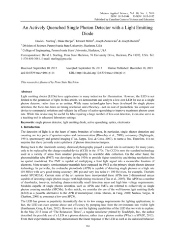
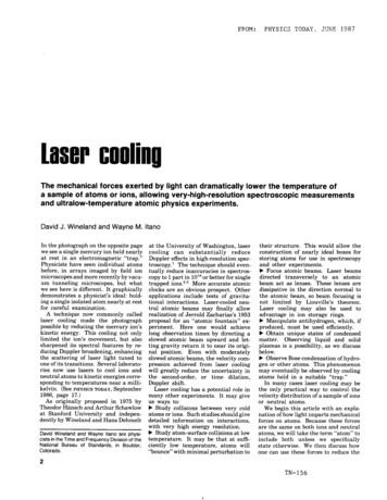
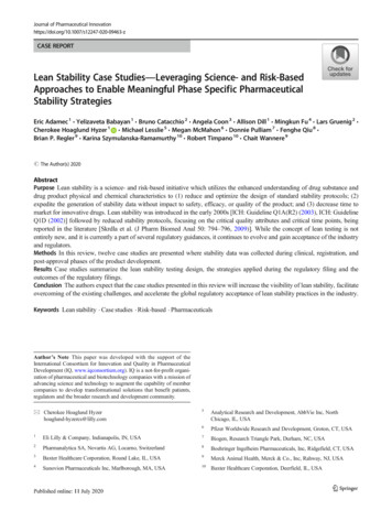
Technical NoteRep Pract Oncol Radiother, 2005; 10(6): 321-325BACKGROUNDERMThe Photon Radiosurgery System – as shown inFigures 2–4 – is usually used to provide localizeddosing to tumour beds at the time of clinical resection. The miniature x-ray source consists of an electron accelerator with a gold target at the end of aprobe. The electrons are accelerated to the desiredenergy level and focused down the probe to strikethe target resulting in an isotropic distribution ofradiation around the tip of the probe [1–3].XRSPatientControl ConsoleFigure 1. Block diagram of the PRS400.Specialised spherical applicators ranging from1.5 to 5 cm are applied. Because of the low energies (20–50 kV) emitted by the miniature X-raysource (XRS), the system can deliver high dosesto relatively small areas of tissue, ensuring thatadjacent normal tissue and critical organs receiveminimal radiation doses [4–7]. This procedurereduces the need for post-surgical radiotherapy.The system requires quality control proceduresto be undertaken and such procedures may include: probe adjustment, beam isotropy adjustment, internal and external monitor stability testing and evaluation of the output dose rate.AIMFigure 2. X-Ray Source (XRS).The aim of the paper is to present the stability ofthe calibration parameters with time.MATERIALS AND METHODSThe PRS-400 System produced by thePhotoelectron Corporation and Carl Zeiss wasused.The verification procedure consisted of 4 steps:– verification of the probe straightness andstraightening if required (Probe Adjust),– tuning the XRS radiation field (IsotropyAdjustment),– testing the Internal Radiation Monitor andExternal Radiation Monitor (IRM and ERMtest),– measuring the XRS Probe radiation outputdose rate (Read Ion Chamber).Probe Adjust ProcedureThe probe is a needle shape structure (Figure 2)with a vacuum, through which the electron beampasses and strikes the target at the end of the probe.Ideally, the probe should be straight in order to assure proper spherical dose distributions. A dedicated optical system was used to check whether the322Figure 3. XRS combined with a balanced floor stand.probe was straight, within the range of a 0.1 mmlimit. If the straightness of the probe was found tobe outside of the allowed limit it was straightenedusing special mechanical equipment.Isotropy adjustmentIsotropy Adjustment is a semiautomatic procedure. It is used to optimize the isotropy of theemitted X-ray beam. The probe was inserted
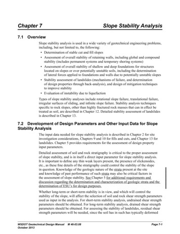
Rep Pract Oncol Radiother, 2005; 10(6): 321-325Orlef A et al – Radiosurgery system XRS Probe deviation0.12limit0.10[mm]0.080.060.040.020.00into a special device containing five photodiodes, placed symmetrically around the probe.During beam emission, the signal from the diodes was analyzed. The degree deviation, as apercentage, between the signals from each of thephotodiodes was taken into consideration. ThePRS system performs self-calibration in order toensure that differences between results from diode to diode are minimal (in the range of 6%).During treatment, an Internal Radiation Monitorand an External Radiation Monitor were used to assess the stability of the beam and the dose given tothe patient. As a result of the IRM calibration procedure, the count rate, in Hertz and corresponding to the output dose rate, could be determined.Using the IRM count prior to treatment, the totalIRM count required for planned doses could becalculated. Besides treatment time, this IRM countdata must be entered into the PRS console prior totreatment. This is a necessary safety requirement.200300400days500600700 800Isotropy5.905.855.805.755.705.655.60IRM/ERM test100Figure 5. Deviation of the needle [mm].[%]Figure 4. The output dose rate in water was determined from themeasurement in air using a dedicated device.00100200300400days500600700 800Figure 6. Differences in beam isotropy [%].treatment). Checking the straightness of the needle is a basic test. It influences the results of theother measured parameters (isotropy, dose rates).Deviation of the needle, measured in mm, is presented in Figure 5.The average deviation in needle straightness, fromthe optimal position, was 0.035 mm (SD 22.1%),well within the tolerance limit (0.1 mm).Output Dose Rate MeasurementsIsotropyFor the purpose of measuring the output doserate, a parallel plate ion chamber (type 23342) andthe UNIDOS (PTW) electrometer were used. Theoutput dose rate in water was determined fromthe measurement in air using a dedicated device(Figure 4). The percentage depth dose curve forall applicators was evaluated according to the procedures and specifications of the manufacturer.The differences in beam isotropy, as a percentage, between diode readings is presented inFigure 6. The average isotropy amounted to5.754, SD 0.3%IRM TestThe data for IRM count is presented in Figure 7.RESULTSDuring the last 2 years over 90 calibration procedures have been performed (one before everyThere are two groups of data visible in Figure 7. Theaverage count value for the first group was 8.251·104Hz (SD 0.3%) and for second group, 8.143·104 Hz323
Technical NoteRep Pract Oncol Radiother, 2005; 10(6): 321-325Internal Radiation Monitor8.40XRS output dose rate2.908.30Counts x E 0400days500600700 800Figure 7. Data for IRM count.Internal Radiation Monitor3.20Counts x E 5Dose rate 500600700 800Figure 9. Measurements of output dose rate data.3.402.200400days500600700 800Figure 8. ERM count rate data.151413121110987654321040mA, 50kV without applicator40mA, 50kV applicator 1.5 cm40mA, 50kV applicator 3.0 cm051015 20 25 30 35Depth in water [mm[4045 50(SD 0.3%). The reason for this difference was theuse of a second XRS control console.Figure 10. Depth dose curves for applicators used (at 50 kV).ERM Testby internal and external monitors. After checking the system it was found that the probe was notsufficiently straight (with the range of 0.1 mm).The ERM count rate data is presented in Figure 8.The average value was 2.931·105 Hz, SD 3.1%.CONCLUSIONSOutput Dose Rate MeasurementsMeasurements of output dose rate data are presented in Figure 9. The average value was 2.735Gy/min, SD 0.8%.All calibration parameters remained stable within the observed period of time (except for IRMcount rate). The depth dose curves for some applicators used, at an energy of 50 kV, are presentedin Figure 10. The dose falls off approximately bya third power of the distance.In a few cases, the treatment session was interrupted owing to dosimetric problems, as determined324High stability of the calibration parameters ofthe Photon Radiosurgery System were observed.The essential factor having an influence on thestability of the system during radiotherapy procedures is the straightness of the needle shapedprobe. That being the case, before any radiotherapy procedure, the measurement of probe deviation is an absolute requirement.REFERENCES:1. Dinsmore M, Harte KJ, Sliski AP et al: A newminiature x-ray source for interstitial radiosurgery:Device description. Med Phys, 1996; 23: 45–52
Rep Pract Oncol Radiother, 2005; 10(6): 321-325Orlef A et al – Radiosurgery system 2. Beatty J, Biggs PJ, Gall Kenneth et al: A newminiature x-ray source for interstitial radiosurgery:Dosimetry. Med Phys, 1996; 23: 53–625. Garrett P, Pugh N, Ross D et al: Intraoperativeradiation therapy for advanced and recurrent headand neck cancer. Int J Radiat Oncol Biol Phys,1987; 13: 785–883. Yanch JC, Harte KJ: Monte Carlo simulationof a miniature, radiosurgery x-ray tube using theITS 3.0 coupled electron-photon transport code.Med Phys, 1996;23: 1551–586. Reitsamer R, Peintinger F, Sedlmayer F et al:Intraoperative radiotherapy given as a boost afterbreast-conserving surgery in breast cancer patients.Eur J Cancer, 2002; 38: 1607–104. Abe M, Takahashi M, Manabe T et al: Intraoperative radiotherapy in carcinoma of the stomachand pancreas. World J Surg, 1987; 11: 459–647. Vaidya J, Baum M, Tobias J et al: The noveltechnique of delivering targeted intraoperative radiotherapy (Target) for early breast cancer. EJSO,2002; 28: 447–54325
- tuning the XRS radiation fi eld (Isotropy Adjustment), - testing the Internal Radiation Monitor and External Radiation Monitor (IRM and ERM test), - measuring the XRS Probe radiation output dose rate (Read Ion Chamber). Probe Adjust Procedure The probe is a needle shape structure (Figure 2) with a vacuum, through which the electron beam