Transcription
USB TAP Probe User GuideDocument Number: UTAPUGRev. 10.x, 06/2014
USB TAP Probe User Guide, Rev. 10.x, 06/20142Freescale Semiconductor, Inc.
ContentsSection numberTitlePageChapter 1Introducing CodeWarrior USB TAP probe1.1 What is USB TAP probe?. 51.1.1 Product highlights. 61.1.2 Debugging environment.71.1.3 USB TAP probe benefits.71.1.4 Target connections. 71.2 Operating requirements.71.2.1 Standard electrostatic precautions.81.2.2 Electrical requirements. 81.2.3 Operating temperature.81.2.4 Target requirements. 81.3 Related documentation.9Chapter 2Connecting to target and your host computer2.1 Debug port connector information.112.2 Connecting to target system.122.2.1 Connecting USB TAP cable to target debug port header. 122.3 Connecting to host computer. 122.4 Setting debug port clock frequency. 132.5 What to do next.13Chapter 3Using USB TAP probe3.1 USB TAP probe system startup. 153.1.1 Starting USB TAP probe.153.2 Notes on using USB TAP probe. 153.2.1 Run/Pause/Mixed mode states. 163.2.2 Breakpoints in exception/interrupt handlers. 16USB TAP Probe User Guide, Rev. 10.x, 06/2014Freescale Semiconductor, Inc.3
Section numberTitlePage3.2.3 Connecting to multiple USB TAP probes.17Chapter 4Hardware specifications4.1 Connectors and LEDs. 194.1.1 Run/Pause indicator. 194.1.2 Transmit/Receive indicator. 204.1.3 USB connector. 204.1.4 Debug port connector.204.2 USB TAP probe specifications. 214.2.1 Electrical characteristics. 214.2.2 Physical characteristics. 21Chapter 5JTAG/COP connector information5.1 Notes specific to MPC8240, MPC8241, and MPC8245. 275.1.1 Signal width example.27Chapter 6DPI connector informationChapter 7ColdFire BDM connector informationChapter 8OnCE connector informationChapter 9USB TAP probe firmware (Loader)9.1 USB TAP probe internal software overview. 419.1.1 Loader software.419.1.2 Dispatcher software.419.2 Reprogramming USB TAP firmware image.429.2.1 To reprogram the USB TAP firmware image. 429.3 What to do next.43Chapter 10TroubleshootingUSB TAP Probe User Guide, Rev. 10.x, 06/20144Freescale Semiconductor, Inc.
Chapter 1Introducing CodeWarrior USB TAP probeThe CodeWarrior USB TAP probe is a cost-effective tool that helps you develop anddebug a number of processors and microcontrollers. This chapter introduces you to theUSB TAP probe.This chapter explains: What is USB TAP probe? Operating requirements Related documentationCAUTIONThe USB TAP probe contains components that are subject todamage from electrostatic discharge. Whenever you are using,handling, or transporting the USB TAP probe, or connecting toor disconnecting from a target system, always use proper antistatic protection measures, including static-free bench pads andgrounded wrist straps.1.1 What is USB TAP probe?The USB TAP probe uses advanced emulation technology to provide control of andvisibility into your target system. Combined with the CodeWarrior IDE, the USB TAPspeeds the debugging process by letting you interactively control and examine the state ofyour target system.USB TAP Probe User Guide, Rev. 10.x, 06/2014Freescale Semiconductor, Inc.5
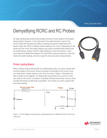
What is USB TAP probe?Figure 1-1. USB TAP probe with USB 2.0 cable1.1.1 Product highlightsThe USB TAP probe has these features: Supports the following systems: Power Architecture processors, StarCore processors,56800 Hybrid Controllers (processors and microcontrollers), and ColdFire processors. Supports all CPU core speeds. Lets you control and debug software running in-target, with minimal intrusion intotarget operation. Lets you debug code in cache, ROM, RAM, and flash memory. Provides high performance: Split-second single-step execution. Capable of download speeds greater than 12 MB per minute from host to target.NOTEThe actual download speed depends on the targetprocessor, the debug port's clock frequency, thenetwork speed, and the debugger. Supports one USB 2.0 connection.Supports both big and little endian byte-order.Automatically supports target signal levels from 1.8V to 3.3V.Software debug capabilities including: Controlling instruction execution. Display and modify target memory. Handles multicore and single core processors equally well.USB TAP Probe User Guide, Rev. 10.x, 06/20146Freescale Semiconductor, Inc.
Chapter 1 Introducing CodeWarrior USB TAP probe Examine and modify any processor registers.Run to breakpoints in ROM, RAM, or flash memory.Single-step through source and assembly language code views.Single-step into, over, or out of functions.1.1.2 Debugging environmentThe USB TAP probe works with the CodeWarrior debugger to give you control over theemulation functions and your target system.1.1.3 USB TAP probe benefitsThe USB TAP probe provides these key benefits: Visibility: The USB TAP probe makes it possible for you to observe registers and thecurrent state of target memory. You can halt program execution at predefined statesand examine the data for a particular program state. Control: You can conveniently control the state of the target system by downloadingcode, manually modifying processor registers and memory, single-stepping throughthe code, or setting breakpoints.1.1.4 Target connectionsThe USB TAP probe connects to your target through the standard debug port for theprocessor family and supports a single target connection. The USB TAP probes areavailable in the following Freescale versions: JTAG/COP for Power Architecture targetsDPI for Power Architecture MPC8xx and MPC5xx targetsBDM for ColdFire targetsOnCE for StarCore, and 56800 Hybrid ControllersFor information on connecting to a target, see Connecting to target and your hostcomputer topic.USB TAP Probe User Guide, Rev. 10.x, 06/2014Freescale Semiconductor, Inc.7
Operating requirements1.2 Operating requirementsBefore setting up your system, you should make sure that the operating environment isprepared.1.2.1 Standard electrostatic precautionsThis instrument contains static-sensitive components that are subject to damage fromelectrostatic discharge. Use standard ESD precautions when transporting, handling, orusing the instrument and the target, when connecting/disconnecting the instrument andthe target, and when removing the cover of the instrument.We recommend that you use the following precautions: Use wrist straps or heel bands with a 1 MW resistor connected to ground. On the work surface and floor, use static conductive mats with a 1 MW resistorconnected to ground. Keep high static-producing items, such as non-ESD-approved plastics, tape andpackaging foam, away from the instrument and the target.The above precautions should be considered as minimum requirements for a staticcontrolled environment.1.2.2 Electrical requirementsThe USB TAP probe is powered through the USB cable and does not use an externalpower supply. It is designed to be plugged directly into a host computer, but also canwork with self-powered hubs. Bus-powered hubs may be unable to provide sufficientpower for the USB TAP probe, which requires 200 mA. If insufficient power is available,your host operating system will indicate this failure and the probe will go into a lowpower suspend mode. If your hub is not able to provide sufficient power, connect theUSB TAP probe directly to your host PC, or purchase a self-powered USB hub.1.2.3 Operating temperatureThe USB TAP probe can operate in a temperature range of 0 to 40 C (32 to 104 ºF).USB TAP Probe User Guide, Rev. 10.x, 06/20148Freescale Semiconductor, Inc.
Chapter 1 Introducing CodeWarrior USB TAP probe1.2.4 Target requirementsThe USB TAP probe automatically supports target signal levels from 1.8V to 3.3V.NOTEIn the case of the Power Architecture, for the USB TAP probeto properly stop and restart a JTAG/COP target processor, theQACK signal must be pulled low. The USB TAP probe pullsthis signal low through the JTAG/COP connector.1.3 Related documentationThis manual describes the procedures for unpacking the USB TAP probe, setting up USBcommunications, and connecting the probe to your target system.The CodeWarrior documentation explains how to install and configure the CodeWarriorIDE and debugger.USB TAP Probe User Guide, Rev. 10.x, 06/2014Freescale Semiconductor, Inc.9
Related documentationUSB TAP Probe User Guide, Rev. 10.x, 06/201410Freescale Semiconductor, Inc.
Chapter 2Connecting to target and your host computerTo run your software using the USB TAP probe, you must have working target hardware.This chapter explains how to connect the USB TAP probe to such hardware and to yourhost computer.This chapter explains: Debug port connector informationConnecting to target systemConnecting to host computerSetting debug port clock frequencyWhat to do nextCAUTIONThe USB TAP probe contains components that are subject todamage from electrostatic discharge. Whenever you are using,handling, or transporting the USB TAP probe, or connecting toor disconnecting from a target system, always use proper antistatic protection measures, including using static-free benchpads and grounded wrist straps.2.1 Debug port connector informationThe USB TAP probe is a powerful development tool for use with a wide variety ofprocessors that use either JTAG/COP, DPI, ColdFire BDM, or OnCE debug interfaces.The following sections describe the debug port connector specifications: JTAG/COP connector informationDPI connector informationColdFire BDM connector informationOnCE connector informationUSB TAP Probe User Guide, Rev. 10.x, 06/2014Freescale Semiconductor, Inc.11
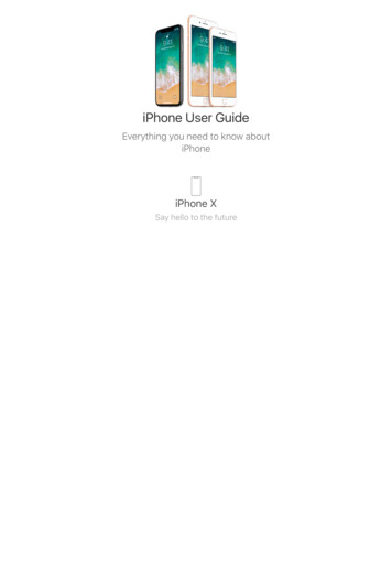
Connecting to target system2.2 Connecting to target systemCAUTIONFailure to properly connect the USB TAP probe to the targetmay damage the probe or target. Verify all connections beforeapplying power.The target system must have a debug port header that you can directly connect to theUSB TAP probe. Make sure that you properly align the USB TAP multi-pin socketconnector with the multi-pin header on your target system.NOTEPin 1 is clearly marked on the gray ribbon cable by a red linedown one side of the cable and a small triangle in the plasticsocket.2.2.1 Connecting USB TAP cable to target debug port header1. Turn off the power to the target system.2. Make sure that the USB cable from the USB TAP probe is not connected to the hostcomputer.3. Make sure that pin 1 of the gray ribbon cable connector aligns with pin 1 on thetarget's debug port header.The figure below shows pin 1 of the USB TAP probe.Figure 2-1. USB TAP probe4. Gently (but firmly) press the connector onto the target system debug port header.This is how you can connect the USB TAP cable to the target debug port.USB TAP Probe User Guide, Rev. 10.x, 06/201412Freescale Semiconductor, Inc.
Chapter 2 Connecting to target and your host computer2.3 Connecting to host computerTo connect to the host computer:1. Connect one end of a USB 2.0 cable to a USB port on the host computer.2. Connect the other end of the cable to the CodeWarrior USB TAP probe USBconnector.3. Apply power to the target system.This is how you can connect to the host computer.2.4 Setting debug port clock frequencyThe debug port on the target is a synchronous interface clocked by the TCK or DSCKsignal. The base frequency is set by the debugger and can be adjusted when you set up aproject in the debugger preferences or configuration options.NOTEFor directions on how to set the debug port clock frequency,please see the CodeWarrior documentation.Some slow targets might not be able to operate at the initial default rate. Therefore, youmay have to adjust the debug port clock rate.NOTEBecause of variations in the design of target systems, it is notpossible to guarantee that all systems can be operated at themaximum debug port clock rates. These variations includecircuit impedances, trace lengths, and signal terminations. Youmay need to select a lower clock rate to get reliable operation.2.5 What to do nextIf you have not already done so, you can now install the CodeWarrior software. See theIDE Users Guide or your targeting manual for information on how to configure thedebugger and run a confidence test.For additional information about using the USB TAP with your target system, see UsingUSB TAP probe topic.USB TAP Probe User Guide, Rev. 10.x, 06/2014Freescale Semiconductor, Inc.13
What to do nextUSB TAP Probe User Guide, Rev. 10.x, 06/201414Freescale Semiconductor, Inc.
Chapter 3Using USB TAP probeThis chapter provides system startup procedures, explains how the USB TAP probeworks, and provides important information about using the system. This chapter explains: USB TAP probe system startup Notes on using USB TAP probe3.1 USB TAP probe system startupThis section explains how to start using the USB TAP probe and the debugger.Before starting the USB TAP probe, make sure you have: Connected the USB TAP probe to your host computer with your USB 2.0 Cable. Connected the USB TAP probe to the target system (see Connecting to target andyour host computer topic). Installed the debugger software and properly configured it to communicate with theUSB TAP probe.3.1.1 Starting USB TAP probe1. Apply power to the target system.2. Start the debugger.LEDs are provided to indicate the status of the USB TAP probe. For description ofthe various indicators, see Hardware specifications topic.You are now ready to begin your debug session. For information on using theCodeWarrior debugger, see Targeting manual.USB TAP Probe User Guide, Rev. 10.x, 06/2014Freescale Semiconductor, Inc.15
Notes on using USB TAP probe3.2 Notes on using USB TAP probeThe following topics provide information specific to USB TAP probe operation: Run/Pause/Mixed mode states Breakpoints in exception/interrupt handlers Connecting to multiple USB TAP probesAlso refer to the debugger documentation to become familiar with the system operation.3.2.1 Run/Pause/Mixed mode statesWhen the host debugger is connected to the target via the USB TAP probe, the probe isalways in one of these states (modes): run,pause or mixed mode. The Run/Pause LED onthe probe will indicate the mode. Run mode - in this mode, all target system processor cores execute the target code.The Run/Pause LED will be green. Pause mode - in this mode, all target system processor cores have stopped executingthe target code. The Run/Pause LED will be red. Mixed mode - in this mode, some target system processor cores are in run mode andothers are in pause mode. The Run/Pause LED will be orange.3.2.2 Breakpoints in exception/interrupt handlersCare must be taken when setting breakpoints in exception handler code. A typicalexception consists of a preamble that saves processor context, the actual exceptionhandler, and then a postamble that restores processor context. You can use softwarebreakpoints in the actual exception handler code, but not in the preamble or postamblewhere the processor context is changing.NOTEFor Embedded Power Architecture processors, placing the CPUinto debug mode is just another interrupt. For example: yourcode is in an interrupt epilogue and has just placed the returnaddress into SRR0 when a breakpoint occurs. The breakpointcauses the IP for the address of the breakpoint to be written toSRR0, destroying your original return address. Steppingthrough code which accesses SRR0 and SRR1 exhibits thesame problem.USB TAP Probe User Guide, Rev. 10.x, 06/201416Freescale Semiconductor, Inc.
Chapter 3 Using USB TAP probeTo avoid this problem, always set your breakpoints before or after code which accessesSRR0 and SRR1, and never step through such code. For example, you can set yourbreakpoint anywhere after the interrupt prologue, but before the epilogue.Instructions that involve the SRR0 and SRR1 registers are "MTSPR SRR0/1,Rx""MFSPR Rx,SRR0/1," and "RFI."3.2.3 Connecting to multiple USB TAP probesYou can connect to multiple USB TAP probes from one host computer in theCodeWarrior IDE, however, procedures may differ for each CodeWarrior IDE variant. For CodeWarrior tools that support creating multiple USB TAP probe connections inthe IDE, simply define the connections, entering the unique probe serial number foreach device. The IDE will manage the CCS sessions. For CodeWarrior tools that do not support creating multiple USB TAP probeconnections in the IDE, create a CCS Remote Connection for each, using unique portnumbers. Then for each device, start the CCS Console and configure the connection,specifying the probe serial number. Tools that support creation of only one USB TAPprobe connection within the IDE will not provide an option for entering the deviceserial number.TipIf the CodeWarrior IDE variant requires using separateCCS sessions to connect to each USB TAP probe, and youwould like the setup steps to run automatically when youlaunch the debugger, edit the \ccs\bin\ccs.cfg file with thenew commands.TipIf you are using a USB hub to connect the USB TAP probeto the host computer, be sure to use a powered hub.TipTo set up the debug connection, you will need to know the8-digit USB TAP probe serial number, located on a labelon the bottom of the device.USB TAP Probe User Guide, Rev. 10.x, 06/2014Freescale Semiconductor, Inc.17
Notes on using USB TAP probeUSB TAP Probe User Guide, Rev. 10.x, 06/201418Freescale Semiconductor, Inc.
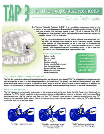
Chapter 4Hardware specificationsThis chapter provides hardware specifications for the USB TAP probe.This chapter explains: Connectors and LEDs USB TAP probe specifications4.1 Connectors and LEDsThe following figures show the various LEDs and connectors of the USB TAP probe.Figure 4-1. USB TAP probe - top viewFigure 4-2. USB TAP probe connector - end viewUSB TAP Probe User Guide, Rev. 10.x, 06/2014Freescale Semiconductor, Inc.19
Connectors and LEDs4.1.1 Run/Pause indicatorWhen the USB TAP probe is powered on, it performs a brief self-test that displays a testpattern on both the Run/Pause and Transmit/Receive LEDs. After the self-test completes,the status LED (labeled RUN/PAUSE) indicates the state of execution on the targetdevice as follows: The LED is green when the target is running.The LED is red when the target is paused.The LED is orange when the target is in mixed mode.The LED is initially unlit and remains so until the debugger is connected to the USBTAP probe.For the definition of run and pause modes, see Run/Pause/Mixed mode states topic.4.1.2 Transmit/Receive indicatorWhen the USB TAP probe is powered on, it performs a brief self-test that displays a testpattern on both the Run/Pause and Transmit/Receive LEDs. After the self-test completes,the transmit/receive LED (labeled TX/RX) indicates the state of the USB interface asfollows: The LED flashes red when the USB TAP probe is powered but has not beenconfigured. The LED flashes green when the USB TAP probe is properly configured. The LED flashes orange when data is being transferred. The LED is unlit if the USB TAP probe is disabled or disconnected.4.1.3 USB connectorThe USB interface consists of a USB type B connector that connects directly to the USBcable provided.4.1.4 Debug port connectorThe debug port connector consists of a 5.5 inch ribbon cable with the appropriate debugconnector attached. The ribbon cable has a red stripe down one side to indicate thelocation of pin 1.USB TAP Probe User Guide, Rev. 10.x, 06/201420Freescale Semiconductor, Inc.
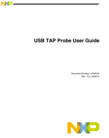
Chapter 4 Hardware specificationsNOTEThe OnCE connector is equipped with a removable plug in pin8. This follows the keying convention for the OnCE header (pin8 should be removed). This plug is removable, in case pin 8 isnot removed from the target OnCE header.4.2 USB TAP probe specificationsBelow figure shows the dimensions of the USB TAP probe.Figure 4-3. USB TAP probe dimensions4.2.1 Electrical characteristicsThe USB TAP probe affects the target processor and target electrical characteristics aslittle as possible. Care, however, should be taken in designing the target to accommodatethe small signal delays associated with any in-circuit probe, emulator, or other testequipment.The USB TAP probe automatically supports target signal levels from 1.8V to 3.3V.4.2.2 Physical characteristicsThe USB TAP probe was carefully designed to be as small as possible. Even so, it maynot physically fit in all target systems.Contact Freescale if you have any special considerations that need review.Below table shows the physical characteristics of the USB TAP probe.USB TAP Probe User Guide, Rev. 10.x, 06/2014Freescale Semiconductor, Inc.21
USB TAP probe specificationsTable 4-1. USB TAP probe - physical characteristicsPhysical characteristicsPower consumptionUSB TAP current consumption from USB cable 200 mAUSB TAP current consumption from target 50 mAEnvironmental RequirementsOperating temperature0 to 40 C (32 to 104 F)Storage temperature-40 to 70 C (-40 to 158 F)Humidity5% to 95% relative humidity,non-condensingPhysicalUSB TAP probe dimensions5.875" x 3.000" x 1.250"(14.92 cm x 7.620 cm x 3.175 cm)Target connector ribbon length5.50" (13.97 cm)Target connector dimensionsHeight (out of probe tip enclosure; above board)0.38" (0.97 cm)Thickness0.20" (0.51 cm)Pin-to-pin spacing0.1" (0.25 cm)JTAG/COP width0.98" (2.49 cm)DPI width0.68" (1.72 cm)OnCE width0.88" (2.24 cm)ColdFire BDM width1.48" (3.76 cm)Figure 4-4. Target connector dimensionsUSB TAP Probe User Guide, Rev. 10.x, 06/201422Freescale Semiconductor, Inc.
Chapter 5JTAG/COP connector informationThe CodeWarrior USB TAP JTAG/COP probe has a 16-pin connector whichautomatically supports target signal levels from 1.8V to 3.3V.The following figure shows the pin assignments of the probe JTAG/COP connector.The following table lists JTAG/COP signal names, direction, pin numbers, descriptions,and drive capabilities for the probe JTAG/COP connector.NOTEAll JTAG/COP signals must meet accepted standards forJTAG/COP signal design. To ensure proper and stableoperation between the USB TAP probe and the target, theJTAG/COP signals must meet the requirements listed in TableA.2.USB TAP Probe User Guide, Rev. 10.x, 06/2014Freescale Semiconductor, Inc.23
Figure 5-1. USB TAP probe for JTAG/COP connector pin assignmentsTable 5-1. USB TAP probe for JTAG/COP signal directionsJTAG/COP pinSignal mnemonicSignal directionDescription1TDOFrom target system30pF load2QACKFrom USB TAP probeconnector100Ohm pull-down3TDIFrom USB TAP probeconnector50mA driver4TRSTFrom USB TAP probeconnector50mA driver5HALTEDBi-directionalOpen-drain, 100Ohm toground when asserted byUSB TAP probe, 35pF loadwhen not asserted6TGT PWRFrom target2MOhm pull-down, plus0.01uF load7TCKFrom USB TAP probeconnector50mA driver8CKSIFrom USB TAP probeconnector50mA driver9TMSFrom USB TAP probeconnector50mA driver10No Connect- n/a -11SRSTBi-directional12No Connect- n/a -13HRSTBi-directionalOpen-drain. 100Ohm toground when asserted byUSB TAP, 35pF load whennot asserted1Open-drain. 100Ohm toground when asserted byUSB TAP, 35pF load whennot asserted1Table continues on the next page.USB TAP Probe User Guide, Rev. 10.x, 06/201424Freescale Semiconductor, Inc.
Chapter 5 JTAG/COP connector informationTable 5-1. USB TAP probe for JTAG/COP signal directions (continued)JTAG/COP pinSignal mnemonicSignal direction14No Connect- n/a -15CKSOFrom target16GND- n/a -Description30pF load11. 4.7KOhm pull-up to buffered TGT PWR.The following table provides a general description of each JTAG/COP signal and theoperational requirements.Table 5-2. USB TAP probe for JTAG/COP signal recommendations/requirementsJTAG/COPpinSignal mnemonicRequirement1TDOMust be wired to the target processor.TDO is an output from the targetprocessor and an input to the USB TAPprobe. The TDO trace run should bekept short and maintain a "two-signalwidth" spacing from any other paralleldynamic signal trace. TDO should havea series termination resistor located nearthe target processor.2QACKMay be wired to the target processor.QACK is an input to most PowerArchitecture processors and mustremain low while the USB TAP probe isconnected to the target. The USB TAPprobe connects this signal internally tothe JTAG/COP GND pin (16) through a100Ohm resistor.3TDIMust be wired to the target processor.The USB TAP probe drives the TDIoutput with up to 50mA. The TDI traceshould be kept short and maintain a"two-signal-width" spacing from anyother parallel dynamic signal trace. TDIshould have an RC termination option atthe processor.4TRSTMust be wired to the target processor.The USB TAP probe drives the TRSToutput with up to 50mA. To gain controlof the processor, the USB TAP probenegates TRST approximately 250milliseconds before negation of HRST.This allows the USB TAP probe to issueCOP commands through the JTAG/COPinterface and gain control of theprocessor upon negation of HRST. TheTRST trace run should be kept short andmaintain
USB TAP probe directly to your host PC, or purchase a self-powered USB hub. 1.2.3 Operating temperature The USB TAP probe can operate in a temperature range of 0 to 40 C (32 to 104 ºF). Operating requirements USB TAP Probe User Guide, Rev. 10.x, 06/2014 8 Freescale Semiconductor, Inc.