Transcription
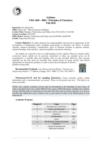
AVAILABLE ACCESSORIES0.5 to 1 mL TubeAdapterp/n 77130681.5 to 2 mL TubeAdapterp/n 7713065SmartView Platformp/n 00-079-009-001642EOperator’s ManualFDA LISTEDRoHSCompliantINSTRUCTIONS FOR DISPOSAL OF WEEE BY USERS IN THE EUROPEANUNIONThis product must not be disposed of with other waste. Instead, itis the user’s responsibility to dispose of their waste equipment byhanding it over to a designated collection point for the recyclingof waste electrical and electronic equipment. The separatecollection and recycling of your waste equipment at the time ofdisposal will help to conserve natural resources and ensure that itis recycled in a manner that protects human health and theenvironment. For more information about where you can drop off yourwaste equipment for recycling, please contact your local city office, wastedisposal service, or where you purchased the product.Made in the USA by200 Shady Lane, Suite 170 Philipsburg, PA 16866 1-866-265-1486 (U.S. only) 1-814-692-7661 www.druckerdiagnostics.comProtected by U.S. Patents #6,811,531, & #D718463 Other Patents PendingP/N 03-0-0002-0039 Rev. N
TABLE OF CONTENTSModel Description . 1Intended Use: . 1Supplied Equipment. 2Features . 2Warranty . 2General Specifications . 3Setup Location . 3Initial Setup Procedure . 4Control Panel . 5Verifying Preset Time and Brake. 6Changing Preset Time and Brake . 6Operation . 7Spinning Balanced Loads . 8Rotor Removal And Installation . 8To remove the rotor: . 8To install the rotor:. 8Care And Preventative Maintenance . 9Cleaning and Disinfection . 10Troubleshooting. 11Emergency Rotor Chamber Entry . 12Calibration Testing . 12Safety . 12Replacement Parts . 13Available Accessories . 14Model 642E has a true “0 RPM” lid locking system. The lid safety lockingsystem keeps the lid locked at all times when the rotor is in motion (evenduring power failure). The centrifuge will not allow entry into the rotorchamber unless the centrifuge has power and the rotor is stopped. Toopen the lid, make sure that the centrifuge is plugged in and, with therotor stopped, press the ‘OPEN / STOP’ button.Note: After the centrifuge has started spinning, it may be possibleto rotate the lid knob enough to cause the pawl to lose contactwith the lid safety switch. If this happens, the centrifuge motormay lose power, but the lid will still remain locked. If the knob isaccidentally moved and this situation should occur, rotate theknob fully clockwise to its stop position and the centrifuge willresume operation.Circuit Breaker: The Model 642E is protected with a 4 Amp circuit breakerlocated at the rear of the machine mounted to the base. Any electricalshort circuit will cause the breaker to cut power to the machine.REPLACEMENT PARTSPart , rubberSwitch, lid safetyRotor, six-place, horizontalMotor, 1/30 H.P., 115 V.A.C. permanent splitcapacitorCapacitor, 4uF, 250V A.C.Electronic timing and locking boardCircuit BreakerPower cordPawl, latch, lidKnob, latch, lidHinge, frictionSeal, lid gasketUniversal Tube Holder for all tubes 75-100 mmLid AssemblyFront Panel LabelPage 13 Drucker Diagnostics 1-814-692-7761 - CustomerService@DruckerDiagnostics.com
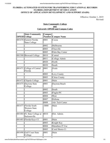
and the rotor stopped. If the lid remains locked after this and will notunlock, the electronics may have been damaged. Contact DruckerDiagnostics for further assistance. To access the rotor chamber, followthe procedure on Page 12, “Emergency Rotor Chamber Entry”.Problem: The run time is not set to the desired length.Solution: Check the run preset by following the instructions on page 8. Ifthe preset is not the desired length, follow the procedure on the samepage to change the run preset time.EMERGENCY ROTOR CHAMBER ENTRYIn the event of power failure, it may be impossible to unlock the lid byconventional means. In this case, entry into the rotor chamber may bemade by removing the latch label and using apen to manually disengage the lockingmechanism (see photo). Pull the mechanismtowards the control panel and then unlatchand open the lid. If the unit is damaged,contact your authorized dealer or DruckerDiagnostics.CALIBRATION TESTINGIt is recommended that the top speed be tested every two years forcontinued safe operation. Contact Drucker Diagnostics for furtherinformation or testing availability.SAFETYThe Model 642E complies with US, Canadian, and European Safety standards.Lid Safety Switch: The Model 642E lid is secured to the top of the cabinetby a latching knob and pawl system. When the knob is rotated clockwise,the pawl grips the underside of the cabinet opening and prevents the lidfrom opening. A mechanical stop positions the pawl and prevents it fromrotating completely. When rotated to the stop position, the pawl makescontact with a micro–switch mounted underneath the cabinet top. The lidsafety switch prevents the centrifuge from operating while the lid is open.An indicator light on the front of the machine will light up when the lidhas been latched properly.Lid Safety Interlock System: In addition to the Lid Safety Switch, theDrucker Diagnostics 1-814-692-7761 - CustomerService@DruckerDiagnostics.com Page 12WARNING: For the safety of both the operator and servicepersonnel, care should be taken when using this centrifuge ifhandling substances that are known to be toxic, radioactive orcontaminated with pathogenic microorganisms. When Risk Group IImaterials are used, (as identified in the World Health Organization“Laboratory Bio-Safety Manual”), a Bio-Seal should be employed.The Bio-Seal accessory for the model is the non-aerosol shield capwith appropriate tube holders (contact Drucker Diagnostics topurchase). In the event that materials of a higher risk group arebeing used, more than one level of protection must be provided.The use of flammable or explosive materials as well as those materialswhich have a vigorous chemical reaction is prohibited.For your safety and the durability of your machine, never transport orstore centrifuge with tube holders inside machine.Users should also comply with the specimen receptablemanufacturer’s specific instructions for use, in addition to any otherprotocols established by the testing organization.MODEL DESCRIPTIONThe Model 642E is a continuous-duty, electronically-controlled horizontalcentrifuge with a lid safety interlock system. The unit is controlled by anelectronic push–button timer that has been preset for ten (10) minutes,for precise spin times and ease of use. Samples can be safely viewedthrough the transparent lid. Entry into the machine is restricted duringoperation by the safety interlock system. The Model 642E features alighted control panel that displays the status of the machine, easilyviewable from a distance.For warranty information, see page 2 of this manual.INTENDED USE:General purpose laboratory centrifuge, intended for the density-basedseparation of fluids through centripetal acceleration.Page 1 Drucker Diagnostics 1-814-692-7761 - CustomerService@DruckerDiagnostics.com
SUPPLIED EQUIPMENTOne (1) six–place horizontal rotorSix (6) universal 75-100 mm tubeholdersTwo (2) 0.5 to 1 mL tube adaptersTwo (2) 1.5 to 2 mL tube adaptersP/N 7786061P/N 7713079P/N 7713068P/N 7713065The rotor and accessories are rated for a rotation frequency of 4,000 RPM.For optional accessories, see the last page of this manual.FEATURES Swing–out horizontal rotor design, incorporating a unique tubeholder that produces horizontally separated samples and spinsboth 75 and 100 mm tubesCool–Flow air flow design that prevents overheating of samplesHeavy gauge steel construction for safety and durabilityLid safety switch that prevents the centrifuge from operatingunless the lid is closed and latchedAutomatic safety lid lock, engaged anytime the rotor is in motionRemovable rotor for easy cleaningBrushless permanent split capacitor AC motorClear lid for safe observation of samples and optical calibration ofspeedElectronically controlled timed operation (see pg. 6)Push-button operationIndicator lights:ColorStatus‘RUNNING’GreenPower is applied to the motor‘LATCHED’YellowLid is closed and latched‘UNLOCKED’RedLock system is deactivated Both the LATCHED and UNLOCKED LEDs must be illuminated to open the centrifuge.If the UNLOCKED LED is not illuminated, the lid cannot be opened.WARRANTYDrucker Diagnostics warranties that this centrifuge is free from defects inworkmanship and parts for 2 years.TROUBLESHOOTINGNote: The latch must be turned completely clockwise to its stop positionin order for the centrifuge to operate.Problem: The rotor does not spin freely.Solution:o Make sure nothing has fallen into the rotor chambero If there is nothing obstructing the rotor, the rotor may bedamaged. Contact Drucker Diagnostics for further assistance.Problem: Excessive noise when the machine is running.Solution:o Check to see that the load is balanced.o Make sure that nothing has fallen into the rotor chamber.o Make sure that the nut in the center of the rotor is tight.o Have a technician test the motor and replace it if necessary.Problem: The Centrifuge does not spin.Solution:o Check the electrical outleto Make sure the lid latch is turned completely clockwise to its stopposition. When the lid is closed properly, the latch light on thecontrol panel will illuminate.o Check the circuit breaker switch at the bottom left of themachine. If the switch is white, the breaker has tripped. ContactDrucker Diagnostics for further assistance.o The printed circuit board may be damage. Have a technician testand replace the circuit board if necessary.Problem: The latch light does not come on when the lid is closed.Solution:o Make sure that the unit has power.o Make sure the lid latch is turned completely clockwise to its stopposition. The latch makes contact with a switch underneath thefront top of the cabinet. If this switch is not activated. The lightwill not tur on the machine will not runProblem: The machine does not unlock after a run has completed.Solution: The lid should remain locked until the rotor has nearly come toa complete stop and then unlock for 60 seconds. If additional unlock timeis needed, press the ‘OPEN / STOP’ button with the machine plugged inDrucker Diagnostics 1-814-692-7761 - CustomerService@DruckerDiagnostics.com Page 2Page 11 Drucker Diagnostics 1-814-692-7761 - CustomerService@DruckerDiagnostics.com
6.Remove Accessories Before Moving: All tube holders, samples,and caps must be removed from the rotor chamber beforetransporting or storing the centrifuge to prevent damage andinjury.GENERAL SPECIFICATIONSNominal Speed (Horizontal)Nominal RCF (Horizontal)Maximum capacity (Horizontal)Overall Dimensions (H x W x D)Centrifuge Motor:Maximum Acceleration TimeProtection BreakerTimerCLEANING AND DISINFECTIONTo prolong the life of the centrifuge cleaning and disinfection isrecommended every six months, or whenever there is a spillage or tubebreakage. Contaminants must be removed immediately, or corrosion andpremature degradation of components can occur.1. Unplug the centrifuge before cleaning.2. Apply cleaning solutions with a towel or cloth. Do not submergethe centrifuge in water or other cleaning solutions as this willcause damage and void the warranty.3. ONLY isopropyl alcohol, soap and water, or a 10% (5500 PPM)bleach solution should be used for cleaning and disinfection ofthe centrifuge and accessories.4. All surfaces must be dried immediately after cleaning anddisinfecting.5. TBQ Germicidal products shall not be used, as they will causedamage to the centrifuge and void the warranty.6. The use of fully/partially halogenated hydrocarbons, ketones,esters, ethers, benzyls, ethyl benzenes, and all other chemicalsnot prescribed by the manufacturer shall not be used as theymay cause damage to the rotor chamber, rotor, tube holders,accessories and centrifuge exterior and void the warranty.7. It may be necessary to remove the rotor and clean the rotorchamber. Follow the instructions on page 8 to remove andreinstall the rotor.Drucker Diagnostics 1-814-692-7761 - CustomerService@DruckerDiagnostics.com Page 10Current RequirementVoltage RequirementFrequencyWeight3,380 ( /- 100) RPM *1,600 ( /- 90) xg60 mL (6 x 10 mL)8.75 in. x 11.75 in. x 14 in.1/30 HP, p.s.c. motor10 seconds4 Amp. re–settableelectronic, 1 to 30 minutespreset to 10 minutes, /– 1%1.9 Amps120 ( /- 10) Volts60 Hz11 lbs* Speed range is established and verified with 120 volts at the electricaloutlet. Speed range may vary depending on actual outlet voltage.Any use other than those specified by the Manufacturer is explicitly prohibited.Maximum sample density is 1.15 grams / mL, (water density 1.0 grams / mL)SETUP LOCATION1.2.Unpack the centrifuge and verify that all of the suppliedequipment is present.Choose a setup location which meets the following criteria:a. A clearance height of 20” (50.8cm) is required to open thelid.b. The clearance envelope is the space around the centrifugewhich is required for safety. Choose a setup location whichwill allow for a clearance envelope of at least 24” x 24”,(with the centrifuge at the center). No person or hazardousmaterial shall be permitted in the clearance envelope duringoperation. The operator time within the envelope shall belimited to the time necessary for loading, unloading andcentrifuge operation only.c. Proper ventilation is necessary to prevent the overheating ofsamples as well as premature failure of the centrifuge.Choose an area which will allow unencumbered air flow.d. The centrifuge is designed to secure to the operating surfaceby four suction feet. No adjustment is necessary for levelingthe centrifuge, however, the surface should be flat and level.e. Be sure the outlet is always within reach as the line cord isthe means of emergency disconnection!Page 3 Drucker Diagnostics 1-814-692-7761 - CustomerService@DruckerDiagnostics.com
INITIAL SETUP PROCEDUREIf any problems are found during the initial setup procedure, refer to thetroubleshooting section on page 11. For further assistance, contactDrucker Diagnostics at 814-692-7661.1.Plug the centrifuge in to an approved electrical outlet. Forelectrical safety, the unit must always be properly grounded.2. For safety purposes, the locking system is always activated. Todeactivate the lid lock to insert or retrieve samples, press the‘OPEN / STOP’ button on the control panel. The ‘UNLOCKED’indicator light should illuminate. If it does not, refer to page 11 ontroubleshooting. The lid will be unlocked for 15 seconds afterpushing the ‘OPEN / STOP’ button.3. Turn the latch 1/4 turn counterclockwise and open the lid.4. Spin the rotor by hand; check for free and level rotation. If therotor does not spin freely, refer to page 11 on troubleshooting.5. Place the six test tube holders inside the rotor and verify that theyare seated properly.6. Close the lid. Rotate the lid knob clockwise to its complete stopposition. The ’LATCHED’ indicator light should be illuminated. If itis not, make sure that the lid is latched properly. The centrifugewill not run unless the lid is latched and that the ’LATCHED’ light ison.7. Turn the centrifuge on by pushing the ‘START’ button.8. The ‘RUNNING’ indicator light will illuminate.9. The test tube holders will slide up into the horizontal position andthe unit will accelerate to full speed.10. Listen to the sound of the centrifuge. A smooth whirring soundshould be heard. If there are any loud or unusual sounds, stop thecentrifuge by pushing the ’OPEN / STOP’ button immediately andrefer to page 11 on troubleshooting.11. While the machine is running, try to turn the latchcounterclockwise. Power may be cut to the motor but you shouldbe unable to fully turn the latch. If it is possible to turn the latchand open the lid while the unit is running, contact DruckerDiagnostics for assistance. Close and latch the lid.12. Push the ‘OPEN / STOP’ button. The ‘RUNNING’ indicator lightshould go out and the motor should slow to a stop.Drucker Diagnostics 1-814-692-7761 - CustomerService@DruckerDiagnostics.com Page 4CARE AND PREVENTATIVE MAINTENANCEWith proper care and maintenance your centrifuge will provide years oflaboratory service. For proper care, the following steps should be taken:1. Provide Adequate Ventilation: For cooling purposes, the Model642E draws in ambient air through the air intake cover on the topof the lid and exhausts this air in the rear of the base. Thecentrifuge should be placed on a hard smooth surface for goodair circulation.2. Always Spin Balanced Loads: Make certain that you are alwaysspinning a balanced load. The Model 642E has a unique counterbalanced motor mounting design which, along with its rubbersuction feet, produces excellent vibration dampening. However,out–of–balance loads may break glass test tubes and mayproduce unsatisfactory separation results. Proper load balancingwill improve sample separation and extend the life of thecentrifuge. Refer to page 8 on balanced loads for additionalinformation on balancing the load.3. Keep the Tube Holders Clean: NOTE: Always follow the safetyguidelines of your laboratory to properly clean up and/or disposeof materials in the event that a substance known to bepotentially toxic, radioactive or contaminated with a pathogenicmicroorganism is spilt in or on the centrifuge. Small glassfragments left in the tube holder after a tube breakage mayadhere to the next test tube inserted in that holder. When thistube is handled, these fragments may puncture protective glovesand lacerate the operator’s fingers or hand. Remaining fragmentsmay provide stress points on subsequent tubes and result inadditional breakage. If a tube breakage occurs, carefully removethe tube holder. Properly dispose of the sample and tubefragments and thoroughly clean both the inside and outside ofthe tube holder.4. Motor and Electrical Maintenance: The Model 642E uses abrushless permanent split capacitor AC motor. It should not needroutine servicing for the life of the centrifuge. The electricalcomponents are selected for high reliability and should not needroutine service.5. Tube Holder Replacement: It is recommended that the tubeholders be replaced after 24 months of use. Inspect tube holdersregularly for cracks. If cracks are discovered, replaceimmediately.Page 9 Drucker Diagnostics 1-814-692-7761 - CustomerService@DruckerDiagnostics.com
SPINNING BALANCED LOADSYour centrifuge must contain a balanced load in order to work properly.Use the following rules when loading the rotor.Spinning balanced loads will extend the life of the machine and producebetter results.1.2.3.Opposing tube holders must be identicalOpposing tube holders must be empty or loaded with equallyweighted samples.If an odd number of samples is to be spun, fill a tube with waterto match the weight of the unpaired sample and place it acrossfrom this sample.ROTOR REMOVAL AND INSTALLATION13. The lid should remain locked until the rotor has nearly stopped. Ifthe machine unlocks prematurely, contact Drucker Diagnostics forassistance.14. Once the rotor has stopped, the interlock system will becomedisengaged for sixty (60) seconds. The ‘UNLOCKED’ indicator lightwill illuminate during this time.15. To gain entry into the centrifuge after this period has ended,simply press the ‘OPEN / STOP’ button. The lid will unlock forfifteen (15) additional seconds.After the centrifuge has passed this procedure it is ready for operation.CONTROL PANELTO REMOVE THE ROTOR:1.2.3.4.Unlock the centrifuge by pushing the ‘OPEN / STOP’ button andunlatch and open the lid.CAUTION: Unplug the centrifuge from the electrical outlet toeliminate the possibility of electrical shock or other injury.Remove the test tube holders.Remove the nut in the center of the rotor by turning itcounterclockwise (a tool may be required).The rotor is sitting on a cone-shaped adapter. Pull the rotor upand off of this adapter.TO INSTALL THE ROTOR:1.2.3.4.5.Place the rotor back onto the cone-shaped adapter. You mayneed to turn the rotor slightly to line it up properly.The rotor should slide onto the rotor cone freely.Once a proper fit has been achieved, replace the nut and turn ituntil it is hand-tight, (a tool may be required).Replace the tube holders and verify that they are seatedproperly.It is recommended that the initial setup procedures beperformed to ensure that the rotor has been installed correctlyand that no damage has been done to the centrifuge duringeither the rotor installation or possible rotor chamber cleaning.See page 4 for this procedure.Drucker Diagnostics 1-814-692-7761 - CustomerService@DruckerDiagnostics.com Page 8‘RUNNING’‘LATCHED’“UNLOCKED’Lights up when themachine is in operation,(power is being applied tothe motor).Lights up when the lid hasbeen closed and latchedproperly.Lights up to indicate thatthe locking mechanismhas been deactivated,allowing access to therotor chamber.‘START’Begins a new run, (the lidmust be closed, see pg. 7).‘OPEN/STOP’Allows for access into therotor chamber bydisengaging the lockingmechanism. Entry is onlypermitted when the rotor isstopped. Pressing thisbutton during operation willterminate the run andunlock the lid after the rotorhas come to a stop.Page 5 Drucker Diagnostics 1-814-692-7761 - CustomerService@DruckerDiagnostics.com
VERIFYING PRESET TIME AND BRAKENOTE: Your centrifuge must be plugged in.a. Push the OPEN / STOP button to disengage the lock and thenopen the lid.b. Push and hold the START button for approximately three (3)seconds. The Yellow LATCHED indicator light will begin to flash,indicating program mode.c. When you release the START button, the RUNNING indicator lightwill begin to flash. Each flash represents one minute of run time.d. Press the START button to verify the brake setting. When yourelease the START button, the RUNNING indicator light will beginto flash. Each flash represents the brake setting, from 1 to 10.CHANGING PRESET TIME AND BRAKENOTE: Your centrifuge must be plugged in.a. Push the OPEN / STOP button to disengage the lock and thenopen the lid.b. Push and hold the START and OPEN buttons for approximatelythree (3) seconds. The yellow LATCHED indicator light will beginto flash slowly, indicating that you can now program run time.c. Press START one time for each minute of run time desired, froma minimum of 1 minute to a maximum of 30 minutes. The greenSTART indicator light will flash each time you press the STARTbutton.d. Press OPEN to enter the run time. You will now begin to adjustthe brake setting.e. Press START to adjust the brake setting, from a minimum of 1 toa maximum of 10. The green START indicator light will flash eachtime you press the start button.f. When you are finished, press the ‘OPEN’ button to exit. Use theabove procedure to verify the run time and brake setting change.Drucker Diagnostics 1-814-692-7761 - CustomerService@DruckerDiagnostics.com Page 6OPERATIONNOTE: Follow the initial setup procedure on page 4 before initial operation.1.2.3.4.5.6.7.Plug the centrifuge into an approved electrical outlet.Push the ‘OPEN / STOP’ button and then open the lid.Place the test tube samples into the tube holders. Be sure tofollow the rules for balanced loads.Close the lid and turn the lid knob clockwise to its complete stopposition. The ’LATCHED’ indicator light should turn on to indicatethat the latch is closed properly. If the lid knob is not completelylatched, the ‘LATCHED’ indicator light will not turn on and thecentrifuge will not operate!The timer has been set to a preset time of ten (10) minutes. Todisplay or change this time setting, refer to page 6.Turn on the machine by pushing the ‘START’ button on thecontrol panel.The centrifuge should begin to spin. The ‘RUNNING’ indicatorlight should illuminate.IF A PROBLEM IS FOUND DURING A SPIN THAT REQUIRES THECENTRIFUGE TO SHUT DOWN, PRESS THE ‘OPEN / STOP’ BUTTON!8.9.10.11.12.13.The ‘RUNNING’ indicator light will begin to flash when oneminute remains.After time has elapsed, the ‘RUNNING’ indicator light willextinguish and the rotor will slow to a complete stop.The ‘UNLOCKED’ indicator light will illuminate and the lockingmechanism will disengage allowing entry into the rotor chamber.If it does not, refer to page 11 on troubleshooting.Turn the lid knob counterclockwise and open the lid.Remove the samples.If the machine re–locks before the samples are removed, pressthe ‘OPEN/STOP’ button to unlock the lid for an additional fifteen(15) seconds.Page 7 Drucker Diagnostics 1-814-692-7761 - CustomerService@DruckerDiagnostics.com
Feb 3, 2022