Transcription
UNITYThermalDesorberUSER MANUALSEPTEMBER 2006QUI-0002VERSION 5.2
This page left intentionally blankQUI-0002 vs 5.2 September 20062
1 Warnings and disclaimers81.1 Electricity81.2 Compressed gases81.3 Hydrogen gas82 UNITY Preinstallation Check List82.1 Minimum computer specification for UNITY control82.2 GC equipment requirements82.3 Access into the GC oven82.4 GC configuration/parameter selection82.5 Laboratory location92.5.1 Space requirements92.5.2 Recommendations relating to the quality of the laboratory air92.5.3 Recommendations relating to the quality of the laboratory gas lines92.6 Services92.6.1 Power92.6.2 Pressure controlled air supply92.6.2.1 Functions92.6.2.2 Specification required (dryness / purity)92.6.2.3 Consumption102.6.3 Pressure controlled carrier gas supply102.6.3.1 Gas selection - type / purity102.6.3.2 Line pressures and recommended pneumatic control102.6.3.3 UNITY Pneumatic Control Accessories102.6.3.4 Filters103 System description and summary of operation103.1 Parameters and ranges103.2 Sample flow path and key system components113.3 Operational sequence for 2(3) stage desorption mode123.4 Operational sequence for tube conditioning mode193.5 Sample tubes193.6 Tube desorption oven193.7 Tube filters and seals193.8 The cold trap193.9 Cold trap cooling and heating193.10 Gas flow through the cold trap193.11 Trap filters and seals203.12 Split filters203.13 User interface204 UNITY Installation20QUI-0002 vs 5.2 September 20061
4.1 Packing list204.2 Installing the cold trap224.2.1 Trap sorbent selection224.2.2 Packing the cold trap224.2.3 Cold trap installation234.3 Installing the transfer line264.3.1 Connecting the transfer line to the gas chromatograph264.3.2 Installing the fused silica transfer line insert284.3.3 Connecting the transfer line to UNITY284.3.4 Coupling the fused silica transfer line to the GC analytical column294.4 Cabling304.4.1 Power304.4.2 Connecting UNITY to the rest of the analytical system304.4.3 Connecting UNITY to the PC314.5 Connecting the gas supplies4.5.1 Carrier gas31314.5.2 Air4.6 Disconnecting / Connecting the Auxilliary heater315 Switching on.326 Loading the UNITY software326.1 Loading UNITY software onto your PC326.2 Downloading UNITY Control software from the PC to UNITY to initialise the system326.3 The UNITY LED327 Introduction to the principles of two-stage thermal desorption337.1 Capillary cryofocusing337.2 Cold trapping338 Guidance on air sampling8.1 Sorbent selection33338.1.1 Carbotrap CTM (20-40 mesh) / Carbopack CTM (60-80 mesh) / Carbograph 1TDTM348.1.2 Tenax TATM or GRTM348.1.3 CarbotrapTM (20-40 mesh) / Carbopack BTM (60-80 mesh) / GCB1TM/ Carbograph 2TDTM348.1.4 Chromosorb 102TM348.1.5 Chromosorb 106TM358.1.6 Porapak NTM358.1.7 Porapak QTM358.1.8 SpherocarbTM / UniCarbTM368.1.9 Carbosieve SIIITM36QUI-0002 vs 5.2 September 20062
8.1.10 Carboxen 1000368.1.11 Molecular Sieve378.2 Packing Tubes378.3 Diffusive Monitoring378.3.1 Principles and Theory378.3.2 Tube-type Axial Diffusive Samplers388.3.3 Diffusive sampling in practice398.3.4 Radial Diffusive Samplers398.3.5 When diffusive sampling is not applicable408.4 Pumped Air Monitoring9 Guidance on Materials Testing9.1 Direct Desorption of material from tubes4041419.1.1 Solid samples429.1.2 Liquids, emulsions, resins and other semi-liquid products.429.2 Off-line purge and trap into sorbent tubes.4310 Guidance on TD / GC analytical conditions4310.1 Occupational Hygiene4310.2 Ambient / Indoor air4410.3 Materials testing - residual solvents in consumer products4410.4 High boiling components4511 Calibration and preparing and introducing standards11.1 Calibration Method 1. - Introducing standards in the vapour phase using theCalibration Solution Loading Rig11.1.1 Criteria for Method 111.2 Calibration Method 2. - introducing standards directly as liquids11.2.1 Criteria for Method 2464647474711.3 Calculating the expected sample mass.4811.3.1 Diffusive air monitoring for toluene4811.3.2 Pumped air monitoring for n-heptane4811.3.3 Solid sampling for residual acetone4811.4 Quality assurance and calibration4911.4.1 Certified Reference Standard (CRS) tubes4911.4.2 External Quality Assessment Schemes5012 Insertion and removal of a sample tube in UNITY5012.1 Insertion5012.2 Removal5013 Preparing for analysis5113.1 Sample tube orientation for quantitative desorption5113.2 Tube conditioning51QUI-0002 vs 5.2 September 20063
13.2.1Typical parameter settings for conditioning various sorbent tubes5113.2.1.1 Tenax TA / Tenax GR5113.2.1.2 Chromosorb 106 / Chromosorb 1025113.2.1.3 Carbopack B / Carbotrap / GCB1 / Carbopack C / Carbotrap C5113.2.1.4Spherocarb / Unicarb / Carbosieve SIII / Carboxen 1000 / Carboxen 56913.2.1.5Molecular Sieve 13X, Molecular Sieve 5A525213.3 Cold Trap conditioning5214 'About' the UNITY user interface5314.1 Windows platform5314.2 Operating languages5314.3 Status bar5315 UNITY Operation: System 'Ready' status5315.1 Internal system checks5315.2 Checks on external components of the analytical system5416 UNITY Options5416.1 Method options5516.2 Gas options5516.3 Sequence options5516.4 Port options5616.5 Configuration options5616.6 Report options5616.7 Miscellaneous options5617 UNITY Methods5617.1 Controlling method5617.2 Generating a new method5617.3 Saving a new method5617.4 Opening a stored method5717.5 General method file functions5717.5.1Copy method parameters5717.5.2Paste5717.5.3Print method5717.5.4Saving existing methods5718 Schematic display of UNITY status5819 Split on or off in standby5820 The Leak Test5820.1 Description of leak test5920.2 Main causes of Leak Test Failure5920.2.1Wearing of the O-rings which seal the tubeQUI-0002 vs 5.2 September 2006594
20.2.2Interference with the tube seal by fibres and particles5920.2.3Damaged O-rings6020.2.4Leaking split filter tube seal6020.2.5Wearing of the cold trap seals6020.2.6Other causes of leak failures6021 Sample tube purge at ambient temperature6021.1 Functions / objectives6021.2 Control of the carrier gas flows during ambient purge6021.2.1Trap in or out of line6021.2.2Split on or off6021.2.3Determining the prepurge time6122 Desorption modes22.1 Tube conditioning mode22.1.1Parameters22.2 Standard 2(3) stage desorption22.2.1Parameters616162626222.3 Other operating modes6423 Sample tube purge at elevated temperature6424 Practical considerations for sample tube desorption6424.1 Sorbent maximum temperatures6424.2 Importance of desorption flow6524.3 Testing for complete desorption6524.4 Verifying desorption efficiency6625 Setting desorb and split flows6625.1 When should desorb / split flows be measured?6625.2 The Set Gas Flow function6625.2.1What does the system do when I select Set Gas Flows6725.2.2Measuring and adjusting flows during Set Gas Flow6725.2.3To Exit the Set Gas Flows Function6825.3 Gas flow constraints - Minimum settings, maximum settings6825.4 Sample Splitting6825.4.1Calculating analyte masses in the sample tube6825.4.2Analytical column capacity6925.4.3GC system detection limits6925.4.4Calculating Splits7025.4.4.1Zero split - splitless operation7025.4.4.2Single split operation7025.4.4.3Double split operation71QUI-0002 vs 5.2 September 20065
25.5 Gas flow through the analytical column7125.6 UNITY systems with the carrier gas supply to the GC analytical column controlled byelectronic pneumatic control (EPC)7125.7 UNITY systems configured with the accessory for electronic mass flow control of thesplit flow7126 The Trap Heat Function7226.1 When should Trap Heat be used7226.2 The Trap Heat Method7226.3 What does the system do when I select Trap Heat7226.4 Parameters for cold trap conditioning7226.5 Selection of the trap low temperature in Trap Heat Method7226.6 Selection of the Trap Hold time7227 Sample flow path - valve and transfer line - temperatures7327.1 Construction materials7327.2 Temperature ranges7327.3 Transfer line to GC column connection7328 Minimum Carrier Gas Pressure Setting7329 GC Cycle Time7330 Start Run key7431 Stop sequence key7432 Method development7432.1 Guidelines for parameter selection7432.1.1Tube Desorption7432.1.2Trap Desorption7532.2 Method validation7533 Method linking7534 SecureTD - Re-collection for repeat analysis7735 Routine maintenance7735.1 Packing tubes7735.1.1How to pack tubes7735.1.2Lifespan of tubes7835.2 Conditioning tubes7835.3 Long term storage of clean and sampled tubes7835.4 Changing tube seals7835.5 Changing tube filters7835.6 Removing the cold trap7935.7 Packing the cold trap7935.8 Changing the cold trap seals79QUI-0002 vs 5.2 September 20066
35.9 Changing the cold trap filters7935.10 Changing the charcoal filters7935.11 Replacing the fuse8036 Trouble shooting36.1 Contamination - The presence of artifacts in the chromatogram808036.1.1The carrier gas supply8036.1.2Contamination from the sample tubes or cold trap8036.1.3Other potential sources of contamination8136.2 Poor Peak Shape / Peak Splitting8136.3 Carryover of components of interest8136.3.1Carryover in the Sample Tube.8236.3.2Carryover in the cold trap.8236.3.3Carryover in other parts of the sample flow path.8236.4 Poor precision8236.4.1Introduction of standards8236.4.2Low carrier gas pressures/flows8336.5 Poor recovery/loss of sample8336.6 Cold trap cannot attain its low temperature8336.7 High Air/Water background when using MS detectors8436.8 Persistent leak test failures8437 Diagnostics8438 Accessing product and support information on the world Wide Web8438.1 Markes International Limited - Home Page and facilities8438.2 Consumables and Spares8438.3 Applications library8438.4 Technical support8438.5 Downloading software upgrades8538.6 Automation accessories.8539 Trademarks85Appendix One - Uninstalling UNITY software from the computer86Appendix Two - Connecting UNITY to a GC / GCMS System88Appendix Three - Consumables catalogue and enquiry/order form94Appendix Four - UNITY Preinstallation Check List96Appendix Five - Electronic Pnuematic Control Module (UNITYe)99Appendix Six - Discontinued product103Appendix Seven - Multi-purpose Direct Inlet Accessory104Appendix Eight - Mass Flow Controller114QUI-0002 vs 5.2 September 20067
1 Warnings and disclaimers1.1 ElectricityEnsure that the mains cord is correctly wired and that the ground leads of all electrical units are connectedtogether via the circuit ground to earth.Any work undertaken on the incoming AC line components should be performed by a qualified electrician.UNITYTM must be unplugged from the mains before any panels are removed.1.2 Compressed gasesHandle cylinders of compressed gas with care. Avoid knocking valves and ensure that correct valves andgauges are used. If possible, store and site gas cylinders outside the laboratory, firmly clamped inposition.1.3 Hydrogen gasAlthough hydrogen may be used as a carrier gas for standard GC and thermal desorption care must betaken in case the high temperatures involved in thermal desorption cause hydrogenation of reactiveand/or unsaturated species.2 UNITY Preinstallation Check List2.1 Minimum computer specification for UNITY controlIn general a PC with sufficient resources to run 32 bit Windows (95, 98, ME, 2000, XP, NT4(series 4)) willhave adequate performance for controlling UNITY. As such the minimum PC requirement recommendedis a 400MHz Pentium with 64MB RAM and a minimum of 20MB of free disc space (for the UNITY softwareinstallation). A Windows compatible mouse is also required.The user interface requires a minimum SVGA (800x600 pixel) screen resolution and ideally an XGA(1024x768 pixel) screen resolution 256 colour in both cases.The PC requires a free serial comms port for communication with UNITY. An additional serial comms portis required for each of the following accessories: Air ServerTM, ULTRATM, SecureTDTM, Headspace unit.UniSenseTM (UNITY plus sensor) requires two free serial comms ports.UNITY communicates at 57600 baud. Whilst lower baud rates can be programmed, this is notrecommended as it will result in degradation of system performance (most modern PCs will supportcommunication at this speed).A 9 way Null modem cable is supplied for connecting UNITY to the PC comms port.The PC will also require an internet connection if the browser facility, included in UNITY's user interface,is to be used. The browser is not required for system operation.2.2 GC equipment requirementsUNITY is usually connected to a gas chromatograph configured with appropriate conventional or massspectrometer (MS) detectors. No conventional GC injector is required for UNITY operation. Ready andexternal start connections are required on the GC.2.3 Access into the GC ovenThe UNITY heated transfer line is lined with 0.25 mm I.D., 0.35 mm O.D. uncoated deactivated fusedsilica which butt connects with the capillary analytical column inside your GC oven. It is important thatthe heated and insulated portion of the transfer line extends as far as the skin of the GC oven such thatthe GC oven heating begins at the point where heating of the transfer line ends. A 25 mm diameteraccess hole is thus required into the GC, with a 6.5 mm hole in the GC inner oven wall. Furtherinformation is provided in Section 4.3.1.2.4 GC configuration/parameter selectionFrom a GC perspective, UNITY may simply be regarded as a multipurpose, stand alone GC injector forQUI-0002 vs 5.2 September 20068
capillary or 1/8 -inch packed columns. No conventional GC injector is required for UNITY operation. Therest of the GC system - column, oven, data handling, detector, etc. - should be configured and used, asper normal chromatographic practice for the analytes of interest.If multiple applications are to be carried out or if samples are uncharacterised; for example whenmonitoring unknown atmospheres, a good general purpose GC configuration comprises 25-30 m,0.25mm or 0.32 mm ID, 1 or 2 µm phase thickness bonded methyl silicone capillary column witha FID or mass spectrometer detector.2.5 Laboratory location2.5.1 Space requirementsUNITY occupies minimal bench space, being only 12 cm wide, and can sit either side of the gaschromatograph.2.5.2 Recommendations relating to the quality of the laboratory airUNITY is a powerful concentration device and is often used to determine trace levels of organic analytes.It is advisable to store and operate UNITY in a clean laboratory environment with minimal atmosphericconcentrations of organic vapours.2.5.3 Recommendations relating to the quality of the laboratory gas linesAs UNITY is a concentrator, even trace level contaminant’s in laboratory gas lines can becomesignificant interferents in the chromatograms produced. It is recommended that gas lines be constructedof refrigeration-grade copper tubing connected using approved swage-fittings. Laboratory gas line jointsand connections must never be brazed. Position the gas supplies as close as possible to the analyticalsystem i.e. such that the gas lines are as short as possible. Use a high quality, stainless steel diaphragmcylinder head regulator for the carrier gas supply.2.6 Services2.6.1 PowerUNITY is automatically compatible with all conventional mains power supplies ranging from 90 to 255 Vand 50 or 60 Hz. It is not necessary to manually select or switch voltages. The maximum powerconsumption of UNITY is 400 W.2.6.2 Pressure controlled supply of dry air or nitrogen2.6.2.1 FunctionsUNITY requires a pressure-regulated supply of dry air or nitrogen at between 55 and 70 psi both toactuate the main valve and to purge the cold trap box.Note: The dry air / nitrogen supply is critical and UNITY must never be switched or left onwithout this gas supply.For UNITY prior to serial number U-10235 the dry air/Nitrogen the UNITY should never be switched onwithout the supply of dry air / Nitrogen.UNITYs with serial number greater then U-10235 has a built in sensor to prevent damage to the Peltiercell, in the event that UNITY is run without the dry air / Nitrogen supply being switched on. The UNITYstatus bar will read "Equilibrating" and the Trap temperature will not reach the temperature set.It is recommended that a secondary pressure regulator be used to control the supply of dry gas toUNITY in addition to that controlling the general laboratory line pressure. Any conventional pressureregulator should suffice for this and suitable pneumatic control may already be available on your GC.Alternatively, Markes International Ltd. supply a pneumatic control accessory (P/N U-GAS01) for bothair and carrier gas - see section 2.6.3.3. It is recommended that the pressure in the laboratory air linebe 10 psi higher than that supplied to UNITY.2.6.2.2 Specification required (dryness / purity)The compressed air or nitrogen must be dry (dewpoint lower than -35 C.) Conventional aircompressors / nitrogen generators may be used provided the gas produced is adequately dried.QUI-0002 vs 5.2 September 20069
2.6.2.3 ConsumptionDry air or nitrogen flows at 200 ml/min into the cold trap box creating a slight positive pressure andminimising ingress of water from the laboratory atmosphere. If the cold trap box was not purged, icewould quickly build up around the Peltier cell which is maintained at -25 C throughout UNITY operation.Gas consumption for valve actuation is minimal.2.6.3 Pressure controlled carrier gas supply2.6.3.1 Gas selection - type / purityHelium is invariably used as the carrier gas for capillary chromatography and nitrogen for packedcolumn or sensor work. 5.0 grade (i.e. 99.999%) or higher purity gas is recommended in either case.Although Hydrogen may be used as a carrier gas for standard GC and thermal desorption applications,care must be taken in case the high temperatures involved in thermal desorption cause hydrogenationof reactive and / or unsaturated species.2.6.3.2 Line pressures and recommended pneumatic controlUNITY requires a regulated supply of carrier gas at a pressure to suit the analytical column / systemselected. The UNITY gas flow path has minimum ( 2 psi) impact on total system impedance. Suitablepneumatic control for the carrier gas may already be available on your GC. The performance of mostcommon capillary columns is optimised at between 1 and 2 ml/min typically requiring between 10 and30 psi head pressure. High quality pressure regulators incorporating a stainless steel diaphragm arerecommended for carrier gas control. The pressure in the laboratory carrier gas line should be at least10 psi higher than that supplied to UNITY.2.6.3.3 UNITY and Electronic Pneumatic Control (EPC)(Only relevant for installations on Agilent 6890GCs - see Appendix Five)For optimum performance the carrier gas pressure to the EPC module should be regulated toapproximately 15 to 20 psi above the column head pressure.Note: As EPC only controls the carrier gas, suitable pneumatic control of the dry gas will still berequired. A U-GAS01 from Markes International includes a carrier gas regulator to step down thecarrier pressure and a separate regulator and gauge for control of the dry air or nitrogen, and istherefore recommended in this case.Note: When installing onto an existing 6890GC the firmware on the GC must be A.03.08 or later (for Aseries) or N.04.09 (for N-series). To check the firmware version, use the keyboard on the GC press:Options Diagnostics Instrument Status and then scroll down to 'Version' where you will see theversion of the firmware running on the instrument.2.6.3.4 FiltersDeoxo and organic filters should be included in the carrier gas line just upstream of connection to theUNITY-GC analytical system.3 System description and summary of operation(For more detailed information, see Section 22.)3.1 Parameters and rangesSee Table 1 belowQUI-0002 vs 5.2 September 200610
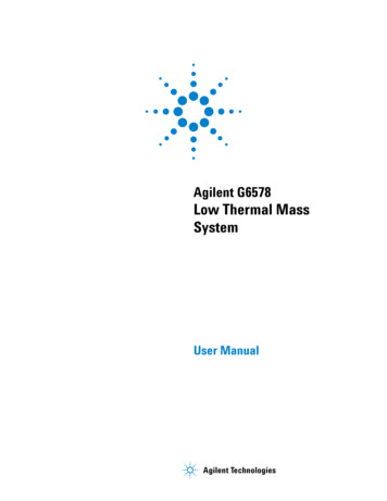
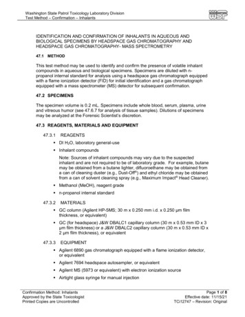
ParameterRangeModeStandard 2(3) Stage Thermal DesorptionTube ConditioningDirect Sampling (only applicable if UNITY is usedin conjunction with multi-purpose Direct InletAccessory)On Line Air (only available if UNITY is used inconjunction with Air Server)Split on in standbyYes/NoAmbient temperature carrier gas purgeTime settable between 0.0 and 99.9 minutes in 0.1minute increments.Split on during tube purgeYes/NoN.B. At least one of theseTrap in-line during tube purgeYes/Nooptions must be selectedElevated temperature purge or stage 1 of primary 35.0 to 350.0 C (settable in 1 increments) for 0 to(tube) desorption (optional)999.9 minutes (settable in 0.1 minute increments)Trap in-line during elevated tube purgeYes/NoSplit on during elevated tube purgeYes/NoN.B. At least one of theseoptions must be selectedPrimary tube desorption (stage 2 if optional 50 to 380 C (settable in 1 increments) for 0 to 999elevated temp. purge employed)minutes (settable in 0.1 minute increments.)Split on during primary (tube) desorptionYes/NoCold trap focusing temperature-15 to 50 C (settable in 1 increments.)Cold trap (secondary) desorption temperature 50 to 400 C (settable in 1 increments) for 0 to 99.9minutes.(settable in 1 minute increments.)Cold trap heating rateMax (ballistic heating reaching 100 C/sec duringfirst critical stages of trap heat) or options between1 and 40 C/secSplit on during secondary (trap) desorptionYes/NoFlow Path Temperature50 to 210 CGC Cycle Time0 to 999.9 minuteMinimum Carrier Gas Pressure0.0 to 99.0 psiTable 1. Parameters and Ranges for UNITY thermal desorber3.2 Sample flow path and key system componentsA detailed schematic of the UNITY flow path in Standby Mode is shown in Figure 2. Key componentsinclude the heated valve (material: PTFE), cold trap (material: quartz), transfer line (material: uncoated,deactivated fused silica) and connecting tubing (Silcosteel.)QUI-0002 vs 5.2 September 200611
3.3 Operational sequence for 2(3) stage desorption mode(For more detailed information, see Section 22.)When a tube is placed and sealed into the flow path of UNITY for conventional 2(3) stage desorption, itundergoes the following sequence of operations:Standby (Figures 1 and 2)Options:- Split flow on or offOptional split flowCarrier InletSample tubeCold trapAnalytical columnFigure 1. Simplified schematic of the UNITY flowpath in standby modeFigure 2. Detailed Schematic of UNITY flowpath in Standby Mode (split off)QUI-0002 vs 5.2 September 200612
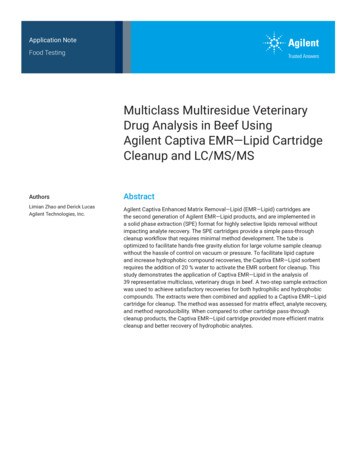
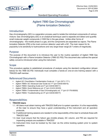
Pressurise (Figure 3)Note: The pressurise stage is actually an inherent part of the leak test and therefore does not appearas a stage on the UNITY status bar (Section 14.3).Carrier InletSample tubeCold trapAnalytical columnFigure 3. Simplified schematic of UNITY flowpath in pressurising sample tube and cold trap modeLeak test (Figures 4a and 4b)Carrier InletSample tubeCold trapAnalytical columnFigure 4a. Simplified schematic of the UNITY flowpath in leak test mode of sample tube and cold trapAnalyticaFigure 4b. Detailed schematic of UNITY flowpath in leak test modeQUI-0002 vs 5.2 September 200613
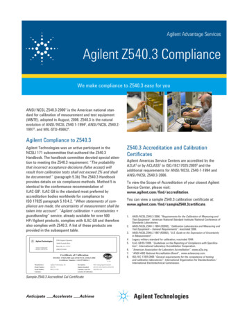
Ambient temperature purge (Figures 5a, 5b and 6)Options:- Split flow on or offCold trap:- in or out of lineNote: Either the split flow or the desorb (trap) flow or both must be open during the purge.Split flowCarrier InletSample tubeCold trapAnalytical columnFigure 5a. Simplified schematic of the UNITY flowpath in ambient temperature purge mode cold trap off lineFigure 5b. Detailed schematic of UNITY flowpath in ambient temperature purge mode cold trap off /on lineQUI-0002 vs 5.2 September 200614
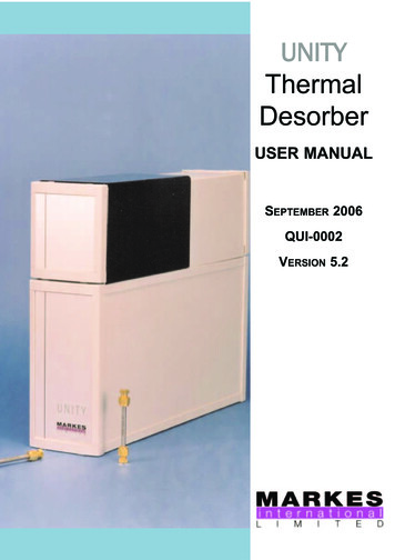
Optional split flowCarrier InletSample tubeCold trapAnalytical columnDesorb flowFigure 6. Simplified schematic of UNITY flowpath in ambient temperature purge mode cold trap on lineElevated temperature purge (optional) (Figures 7a and 7b)Options:- Split flow on or offCold trap:- in or out of lineNote: Either the split flow or the desorb (trap) flow or both must be open during the purgeSplit flowCarrier InletCold trapSample tubeAnalytical columnFigure 7a. Simplified schematic of UNITY flowpath in elevated temperature purge mode - cold trap off lineOptional split flowCarrier InletSample tubeCold trapAnalytical columnDesorb flowFigure 7b. Simplified schematic of UNITY flowpath in elevated temperature purge mode - cold trap on linePrimary (tube) desorption (Figures 8a and 8b)At the start of primary (tube) desorption the tube oven begins to heat (either from ambient or from thetemperature of the optional elevated temperature purge if selected). Note that the tube desorptiontime is measured from the beginning of tube oven heating and not from the time at which thesample tube reaches its desorption temperature.Options:- Split flow on or offQUI-0002 vs 5.2 September 200615
Figure 8a. Tube Desorption - Series of simplified schematics showing analytes being desorbed from thesample tube to the cold trapFigure 8b. Detailed schematic of UNITY flowpath in primary (tube) desorption modeQUI-0002 vs 5.2 September 200616
Pre-Trap Fire Purge (Figure 9)Following primary desorption, the heated valve is moved and carrier gas is flushed through the split tubeand the trap to remove any residual air and water prior to trap injection. It may also be used to dry purgethe cold trap prior to injection when direct desorbing solid or humid samples.Figure 9. Detailed schematic of UNITY flowpath in pre-trap fire purge modeThis purge step is pre-set to run for 18 seconds. If the user requires a different purge time this can beset in View Options Sequence section of the UNITY software (Section 16.4)QUI-0002 vs 5.2 September 200617
Secondary (trap) desorption (Figure 10a & b)Options:- Split flow on or offNote that the flow path of UNITY remains in the trap desorption configuration until the trap hascooled back down below 50 C.Figure 10a. Trap Desorption - Series of simplified schematics showing analytes being desorbed from thecold trap to the analytical column and the sorbent tube cooling to ambientFigure 10b. Detailed schematic of UNITY flowpath in Secondary (trap) desorption mode.QUI-0002 vs 5.2 September 200618
3.4 Operational sequence for tube conditioning mode(See Section 22.1 for further details)The first four stages of operation in tube conditioning mode; - standby, pressurise, leak test and ambientpurge are identical to those described above for 2(3) stage desorption (Figures 2 to 6.)Stage five of tube conditioning is primary (tube) desorption with the split flow on and the cold trap off-line(Figure 7.)3.5 Sample tubesUNITY is compatible with industry standard sample tubes - 3.5-inches (89 mm) long by 1/4-inch (6.4 mm)O.D with 5 mm (stainless steel and coated steel) or 4 mm (glass) I.D. Sorbent is retained in stainlesssteel (or coated steel) tubes using stainless steel (or coated steel) gauzes and a gauze retaining spring.Quartz or glass wool is recommended for retaining the sorbent in glass tubes.3.6 Tube desorption ovenThe UNITY tube desorption oven heats up rapidly ( 150 C/min) at the start of elevated temperature purgeor tube desorption. It begins to cool at the end of primary (tube) desorption and reaches 50 C from 300 Cwithin 10 minutes.3.7 Tube filters and sealsWhen ready for analysis, sample tubes are placed into the cool desorption oven with the sampling(grooved) end pointing to the rear of the instrument. Operation of the lever mechanism seals the sampletube into the UNITY flow path. Temperature resistant Viton O-rings seal onto the outer wall of the sampletube, 2 mm from either end. Each O-ring should last for 1000 tube-sealing operations. In the event offailure, O-rings at both ends of the sample tube are readily replaced by the user. (See Section 35.4.)A porous PTFE filter sits just behind the O-ring in both sample tube seals. These prevent UNITY flowpath contamination in the event that sorbent particles or high boiling sample materials migrate out of thetube. The filters are readily accessed for user replacement. (See Section 35.5.)3.8 The cold trapThe cold trap contains a 2 mm diameter x 60 mm long bed of sorbent (30 to 100 mg depending on sorbentdensity) supported by quartz or glass wool. Note that the length of the first plug of glass wool isincluded in the total 60 mm sorbent bed.3.9 Cold trap cooling and heatingUNITY contains a 2-stage peltier cell, which uniformly cools the entire 60-mm sorbent bed to a minimumof -10 C in ambient temperatures as high as 30 C. N.B. The minimum is reset at -15 C for ozoneprecursor systems. At -10 C, a cold trap packed with an appropriate series of sorbents includingcarbonised molecular sieve, allows quantitative retention of compounds as volatile as ethene and freonsfrom over 500 ml of gas/air. No liquid cryogen is required. With the trap at -15 C quantitative recoveryof ethyne can be demonstrated from over 200 ml of gas/air.Note: C2 hydrocarbons (ethyne, ethene, ethane) and the most volatile freons cannot be sampled usingsorbent tubes at ambient temperatures - Breakthrough volumes are too small for practical use even withthe strongest tube sorbents. These compounds must be collected in bags or canisters or sampled online. These whole air/gas samples are then introduced to the UNITY cold trap using an Air ServerAccessory.Once all the target analytes have been collected and focused in the cold trap, the trap oven heatsballistically reaching rates in excess of 60 C/sec for the first critical stages of trap desorption.Uncompromised capillary chromatography is produced without on-column focusing and with desorptionflows as low as 2 ml/min. This facilitates splitless operation with high-resolution capillary GC.3.10 Gas flow through the cold trapThe UNITY cold trap operates in backflush mode - the sample gas stream enters and leaves the cold trapthrough the narrow-bore/restricted end which points to the rear of the instrument. Backflush desorptionallows use of a series of 2 or 3 sorbents of increasing strength in the cold trap - For example; Tenax TATMQUI-0002 vs 5.2 September 200619
(weak) backed up by Carbograph 1TD TM (medium), backed up by UniCarbTM (strong). This facilitatesthe analysis of wide volatility range samples. (High boiling compounds are retained by and quantitativelydesorbed from the first weak sorbent, without e
UNITY Thermal Desorber USER MANUAL SEPTEMBER 2006 QUI-0002 VERSION 5.2 . QUI-0002 vs 5.2 September 2006 2 This page left intentionally blank. 1 Warnings and disclaimers 8 1.1 Electricity 8 1.2 Compressed gases 8 1.3 Hydrogen gas 8 2 UNITY Preinstallation Check List 8