Transcription
MIL-HDBK-155324 September 1986
MIL-HDBK-155324 September 1986FOREWORDThis sectionof the handbook providesa sample test plan for KIL-STD-1553Bthat may serve severaldifferentpurposes.This sectionis intendedto benoncontractualwhen the entireMIL-HDBK-1553 is referencedin an equipmentspecificationor SOW. In this case the test plan, as well as the rest of thehandbook,providesguidanceto both the DOD procuringengineerand thecontractordesign engineer.This sectionis intended to be contractualwhenspecificallycalled out in a specification,SOW, or when requiredby a DID.If the contractoris requiredto submit a test plan for his RT to the government, he may remove this sectionfrom the handbook and submit it as a portionof his test plan.A betterapproach would be to simply referencethis section.In either case, any and all contractorchanges, alterations,or testingdeviationsto thissectionshallbe separatelylistedfor easy review bygovernment personnel.
MIL-HDBK-1553NOTICE 124 ANDBOOlTO ALL HOLDERSOF MIL-HDBK-1553:1. THE FOLLOWINGIN THE DOCUMENT:PAGES OF MIL-HDBK-1553NEW PAGERETAINTHIS NOTICEPUBLISHEDANDSHOULDBE INSERTEDINITIALPUBLICATIONDATEAppendix A(ii thru vi)(1 thru 67)2.ARE24 September1986AND INSERT BEFORE TABLE OF CONTENTS.3. Holders of MIL-HDBK-1553will verify that additions indicated above havebeen entered.This notice page will be retained as a check sheet.Thisissuance,together with appended pages, is a separatepublication.Eachnotice is to be retained by stocking points until the military standard iscompletely revised or canceled.Custodians:Preparing activity:Air Force - 11Army - ERNavy - ASAir Force - 11ProjectNo. MCCR-0026AMSC: N/ADISTRIBUTIONFSC MCCRSTATEMENTA.Approvedfor publicrelease;distributionis unlimited.
KIL-HDBK-155324 September 1.2.1.35.1.2.1.3.15.1.2.1.3.25.1.2.25.1.2.3OF CONTENTSPAGE ApplicationAPPLICABLE DOCUMENTSStandards DEFINITIONSResponses Broadcast command receivedBusy bit (BUSY) Clear status (CS)1Hi111 1111(BCR)Dynamic bus acceptance bit (DBA)Service request bit (SRB).Message error bit (ME).No response (NR).Respond in form Subsystem flag bit (SF) Terminal flag bit (TF).GENERAL REQUIREMENTSGeneral test requirementsTests for optional requirements.General monitoring requirements.DETAILED REQUIREMENTS Electrical testsOutput characteristics Amplitude Risetime/falltimeZero crossing stabilityDistortion. overshoot and ringingOutput symmetry Output noise Output isolationPower on/off Power on/off noise Power on responseTerminal response timeFrequency stability.Input characteristics Input waveform compatibilityZero crossing distortion Amplitude variationsRise and fall time TrapezoidalSinusoidalCommon mode rejectionInput impedance 111 2222222 2 23333 334444555 56 667777 788 8
MIL-HDBK-155324 September1986TABLE OF .2.2.15.2.2.1.15.2.2.1 AGE8tests8Required remote terminal operationResponse to command words RT response to command words.RT-RT response to command words.Intermessage gap Minimum time Transmission rateError injection Parity Transmit command wordReceive command wordReceive data words Word lengthTransmit command word Receive command wordReceive data words Bi-phase encodingTransmit command word Receive command wordReceive data words Sync encodingTransmit command word Receive command wordData word 8911111111131313131314141414 Message lengthTransmit commandReceive command Mode command word count errorRT to RT word count error.Contiguous data Terminal fail-safe Superseding commandsRequired mode commandsTransmit statusTransmitter shutdown and overrideReset remote terminal Data wrap-around.RT to RT timeout.Bus switchingUnique addressOptional operation Optional mode commandsDynamic bus controlSynchronize Synchronize (without data word).Synchronize (with data word).Initiate self-test Transmit BIT word l.V 15 151515 16161616161617 17 17 181818191920 21222223.'242525252525 2525 26
MIL-HDBK-155324 2.2.5.25.3OF CONTENTSPAGEtransmittershutdownand overrideTerminal flag bit inhibit and overrideTransmit vector wordTransmit last command Status word bits. Service request Broadcast command receivedBusy.Subsystem flagTerminal flag.Illegal command Broadcast mode commands 29293030303131 Broadcast synchronize (without data word)Broadcast synchronize (with data word)Broadcast initiate self-test.Broadcast transmitter shutdown and override.Broadcast selective transmitter shutdownand overrideBroadcast terminal flag bit inhibit andoverride Broadcast reset remote terminal.Broadcast dynamic bus controlError injection-broadcastmessages.Parity:bus controller (BC)-RT broadcastCommand word error Data word error Message length. Be to RT broadcast.Noise rejection tests v2627282832323232333435 36363737373738381986
MIL-HDBK-155324 September1986TABLEOF ssagePAGEundefined10mode codes.12gap messages 39Criteria for acceptance or rejection of aterminal for the noise rejection 545556General resistor pad configuration.General bus configuration.Waveform measurements Zero crossing interval measurementsOutput noise configurationOutput isolation.Transformer coupled common mode configurationDirect coupled common mode configuration.Gap time measurementRT-RT timeout measurement.Configuration for noise rejection testSuggested configurationConfiguration for noiseSuggested configurationfor noise rejectionrejection testfor noise rejection575859 6061 ST PLAN TO MIL-STD-1553B--CROSSREFERENCE 41BMIL-STD-1553BREFERENCE 47CTEST PLAN CHANGESFOR MIL-STD-1553BONLY RIs.51DTEST PLAN CHANGESFOR MIL-STD-1553B.TO TEST PLAN--CROSSV:lNOTICE1 RTs53
MIL-HDBK-155324 September1.01986SCOPE1.1 General.This validationtest plan defines the test requirementsforverifyingthat the designof remoteterminalsmeet the requirementsofMIL-STD-1553B. "Digital Time Division Command/Response Multiplex Data Bus."Aremote terminal is considered to have failed to meet the above requirements ifthat remote terminalfails any test or a portion of any test performedaccording to this test plan.Passing this test plan does not automaticallymean that the remote terminal is acceptable for use by the government.Theremote terminal must also meet all the requirements of MIL-STD-1553B over allthe environmental.EMI, vibration.and application requirementsin the subsystem specification.01.2 Application.This general test plan is intended for design verificationof remote terminals designed to meet the requirements of MIL-STD-1553B. Notice2.Appendix A and B provide cross references between this tes t plan andMIL-STD-1553B.For those remote terminals not required to meet Notice 2.Appendix C and D list the changes in this test plan for MIL-STD-1553Bonlyand MIL-STD-1553B.Notice 1.These requirementsshall apply to the terminalunder test. when invoked in a specification or statement of -STD-15533.0Digital Time DivisionData BusCommand/ResponseMultiplexDEFIHITIONS3.1 Reaponaea.The following are definitions of the responses of the RT asused in this test plan.In each case the status word must have the correctterminal address and unused status bits set to zero.3.1.1Broadeaat command received (BCR).(bit t ;.me fifteen) is set in status wordtransmlt status mode command or a single1as t ccmmand mode command).3.1.2Buay bit (BUSY).CS withstatus word. and no data words.The broadcast command received bit(and no data words in response to adata word in response to a transmitthe busy bit(bittime sixteen)setin the3.1.3Clear statua (CS).The status word may have the busy bit and/orserVl.ce request bit set.All other status code bits in the status word mustbe zero and the associated message must have the proper word count.bus1control
MIL-HDBK-155324 September 1986cs with the service3.1.5Service request bit (SO).eleven) set in the status word.requestbit(bittime3.1.6Message error bit (ME).The message error bit (bi.t time nine) is setin the statusword and no data words (except in response to a transmitlastcommand mode command which requiresone data word).3.1.7No responseto the command.(NR).The addressedterminaldoes not produceany response3.1.8Respond in form.A terminalis said to "respondin form" if itsresponseto an illegalcommand as definedin the paragraphtitled"Illegalcommand" of MIL-STD-1553 consistsof a response formatted as though it were alegal command.3.1.9Subsystem flag bit (SF).seventeen)set in the status word.3.1.10Terminal flag bit (TF).teen) set in the status word.4.0GENERALCS withCS withthesubsystemthe terminalflagflagbitbit(bit(bittimetime nine-REQUIREMENTS4.1 Generaltestrequirements.The followingparagraphsdefinethe configurations,pass/failcriteria,and generalproceduresfor testingremoteterminals(RT).Specifically,this document containsthe test configurationsand proceduresfor the ElectricalTests (5 .1), the Protocol Tests (5.2),andthe Noise RejectionTest (5.3) for MIL-STD-1553 remote terminals.The remoteterminalunder test is referredto as the unit under test (UUT). Proper terminal responsesare defined in each test paragraph.If the hardware/softwaredesignof the UUT does not permit a testto be performed,then adequateanalysisshallbe provided in place of the test resultsto demonstratethatthe design meets the requirementsof MlL-STD-1553 as stated in the test.Any conditionwhich causes the UUT to respond other than as calledout inMlL-STD-1553, to lock up, or requirea power cycle in order to recover for anyreason shall automaticallycause that UUT to fail the test.All occurrencesof responseswith the busy bit set in the status word shall be recorded.Ifthe UUT response does not match the pass criteriafor a particulartest,thenthe UUThas failed that test.4.2 Tests for optionalrequirements.All testsfor optionalrequirementsdefined in 5.2.2 shall be executed if that MlL-STD-1553 option is requiredbythe subsystem specificationor interfacecontrol document (ICD).Any optionalcapabilitiesimplemented in the RT'should also be tested,if possible.Withinthe constraintsimposed by the hardware/softwaredesign, optionalcapabilitiesmust be tested prior to use by system integrators.2
MlL-HDBK-155324 September 19864.3 General monitoringrequirement.In additionto the specifictestsfollow,certainRT parametersmust be continuouslymonitoredthroughouttests.These parametersare:a.b.c.d.e.f.g.h.1.response timecontiguousdataproper Manchester encodingproper bit countodd parityproper word countproper terminaladdress in the status wordreservedstatus and instrumentationbitsin the status word are set to zeroproper syncThe UUT shall have failedparametersfailto meetmeters for all failures.5.0thatallDETAILEDthe test if at any time during the test any of thesethe requirementsof M.IL-STD-1553. Record the para-REQUIREMENTS5.1 Electricaltests.Each test paragraph containsthe requirementsfor bothtransformerand directcoupled stubs.A UUT which provides both transformerand directcoupled stubs must be tested on both stubs.Electricaltests shallbe performed on all buses for UUTs with redundant bus configurations.5.1.1Output characteristics.The followingtestsare designedthat all UUT outputcharacteristicscomply with MIL-STD-1553.shallbe performed afterestablishingcommunicationsbetween thement and the UUT. All output electricaltestsshall use figureResistorPad Configuration,with all measurementstaken at pointotherwisenoted.to verifyThese teststest equiplA, General"A", unless5.1.1.1Amplitude.A valid,legal transmitcommand shall be sent to the UUT,request ing the maximum number of words that it is capable of sending.Theamplit1 de of the waveform transmittedby the UUT shall be measured, peak-topeak, dS shown on figure 2.The pass criteriafor Vpp for transformercoupled stubs shall be 18.0 V m1n1mum, a ld 27.0 V maximum. The pass criteriafor Vpp for directcoupled stubsshall)e 6.0 V minimum and 9.0 V maximum. The maximum and minimum measuredparame':ers,Vpp, shall be recorded.5.1.1.!i.isetilllejfalltime.A valid,legalthe ULT, requestingat least one data word.waveform shall be measured between the 10%shown on figure 2.The measurements shallfallingedges of a sync waveform and a dataand the falltime(Tf) shall be recorded.3transmitcommand shall be sent toThe rise and fall time of the UUTand 90% points of the waveform asbe taken at both the risingandbit waveform.The risetime(Tr)
KlL-HDBK-155324 September 1986The pass criteriashall be 100 ns Tr 300 ns and 100 nsmeasured parameters,Tr and Tf, shall be recorded. Tf 300 ns.TheNote: The risetimeof the sync waveform shall be measured at the mid-crossingof a data word sync, and the fall time of the sync waveform shall be measuredat the mid-crossingof the status word sync.5.1.1.3Zero craningatability.A validlegal transmitcommand shall besent to the UUT, requestingthe UUT to transmitwords having zero crossingtime intervalsof 500 ns, 1000 ns, 1500 ns and 2000 ns.The zero crossingtime shall be measured for both the positive(Tzcp) and the negative(Tzcn)waveforms as shown on figure 3.The pass criteriafor each case shall.:25 ns, 1500 .:25 ns and 2000 25 ns.shall be recorded for each case.be that Tzcp and Tzcn 500 25 ns, 10.00The measured parameters,T;-cp and Tzcn5.1.1.4Distortion,overshootand ringing.A validlegal. transmitcommandshall be sent to the UUT, requestingthe UUT to transmitat least one dataword.The distortionof the waveform, distortionvoltage(VD) shallbemeasured as indicatedon figure 2.Pass criteriashallbe VD .:900 mV peak, line-to-line,for transformercoupled stubs or VD .:300 mV peak, line-to-line,for directcoupled stubs.The worst measured parameter,VD, shall be recorded.5.1.1.5Output aymmetry.A valid legal transmit command shall be sent to theUUT requestingthe maximum number of data words that the UUT is capable oftransmitting.The output symmetry is determinedby measuringthe waveformtail-offat the end of each message.The maximum residualvoltage (Vr) shallbe measured as shown on figure 2. This test shall be run six times with eachdata word in the message having the same bit pattern.The six data word bitpatternsthat shall be used are:8000(HEX), 7FFF(HEX), OOOO(HEX),FFFF(HEX),5555(HEX), and AAAA(HEX)for transformerThe pass criteriashall be Vr 250 mV peak, line-to-line,line-to-line,for directcoupled stubscoupled stubs and Vr 90 mV-p k,aftertime Tt (the ti beginning2.5 us after the mid-bitzero crossingofthe last parity bit).The measured parameter,Vr, shall be recorded for eachbit pattern.5.1.1.6Output noise.The test configurationshown on figure 4 shall be usedto test the UUT inactivebus output noise levels.The test shall be conductedwhile the UUT is in the power-on receive state and the power-off state.Theoutput noise (Vrms) shall be measured at point "A" as shown on figure 4 forboth states.Measurements shall be made with an instrumentthat has a minimumfrequency bandwidth of DC to 10 MHz.The pass criteriashall be Vrms 14.0 mV for transformercoupled stubs andVrms 5.0 mV for directcoupled stubs.The measured parameter,Vrms, shallbe recorded for each case.4
MIL-HDBK-155324 September19865.1.1.7Output isolation.This test shall be performed only if the UUT isconfigured with redundant buses.A valid legal transmit command shall be sentto the UUT requesting the maximum number of data words that it is capable ofsending.The voltage of the output waveform transmitted by the UUT shall bemeasured on the active and redundant bus (or buses).Each data bus shall bealternately activated and measurements taken.The pass criteria shall be that the ratio in dB between the output peak-topeak voltage on the active bus and the output peak-to-peak voltage on allinactivebusesshall be greaterthan or equal to 45 dB (figure 5). Themeasured parameter, output isolation, expressed as a ratio in dB, shall berecorded for each bus combination.5.1.1.8Power on/off5.1.1.8.1 Power on/off noise. A UUT shall limit any spurious differentialoutput during a power-up or power-down sequence. Power shall be applied to theUUT and any outputs from the UUT shall be measured.Power shall be removedfrom the UUT and any output from the UUT shall be measured.Repeat the testten times.The pass criteriashall be:a. For transformer coupled stubs any spurious noise pulsesbe less than or equal to 250 mV peak, line-to-line.b. For direct coupled stubs any spurious noiseless than or equal to 90 mV peak, line-to-line.All measuredrecorded.Note:Thisthe UUT.parameters,outputnoisetest shall be performedamplitudesusingpulsesand pulsethe quenceofon/off powerS.I.I.t.2Power on response.The purpose of this test is to verify that therel.ponds correctly to commands after power is applied to the UUT.Usingthe normal power on sequence for the UUT, repeat the following test sequence aminimuI" of ten times.UlITSt(P 1. Powerthe UUT off.Step 2. Send valid, legal, non-broadcast, non-modea maximum intermessage gap of 1 ms.St pcommandsto the UUT with3. Power on the UUT and observe all the responses for a minimum2 s from the first transmission of the UUT after power on.The pass criteria shall be: step 3 - NR until the first UUT transmission,CS for the first transmission and all responses thereafter 5ofand
MIL-HDBK-155324 September19865.1.1.9Terminal response tiae.The purpose of this test is to verifytime.Thethe UUT respondsto messageswithinthe proper responsesequence shown below shall be performed.commandStep1.A valid legal transmitresponse time measured.Step2.A validresponseStep3.A valid legal RT-to-RT command, with the UUT as the recel.vl.ngterminal.shall be sentto the UUT andthe responsetimemeasured.Step4.A validresponselegal receive commandtime measured.legal mode commandtime measured.shallshallshallbe sent to the UUT andthattestbe sentbesentto the UUTtothe DUTandandthethetheThe pass criteria for step I, step 2. step 3. and step 4 shall be a responsetime between 4.0 and 12.0 us at point A of figure lA and measured as shown onfigure 7. The command words used and the response times shall be recorded.5.1.1.10Frequency stability.The purpose of this test is to verify that thetransmitter clock in the UUT has the proper accuracy and long term stabilityand proper short term stability.The transmitterclock measuredshall beeither the main oscillator output or an appropriate derivative of that clock(e.g either the 16 MHz oscillator or the 1-2 MHz transmitter shift clock).The test sequence shown below shall be performed on the clock output whoseideal frequency is Fi.Step 1.The short term transmitter clocka single period of the waveform.Step 2.Repeat step 1 for at least 10,000 samples and record the minimum(Fsmin) and the maximum (Fsmax) frequency from the samples taken.StepThe transmitter clock frequency shall be measured with a gatetime of 0.1 s and the mean frequency for at least 1.000 samples(Fav) shall be recorded.3.The pass criteriafrequencyshallbe measuredforshall be:Step 1 and 8tep 2 - S81c 100(Fsmax - Fav)/Fav 0.01 andSs2 100(Fav-Fsmin)/FavStep 3 - the magnitudeof Sl 100(Fav-Fi)/Fi 0.01; 0.1.RecordSsl. Ss2 and Sl.5.1.2Input characteristics.The input tests are designed to verify thatmultiplex devices can properly decode bi-phase data.All input electricaltests shall use figure lA or figure IB with all measurementstaken at point"A," unless otherwise noted.For Air Force applications, all input electricaltests shall use figure lB. with all measurementstaken at point "A" unlessotherwise noted.6
MIL-HDBK-1SS324 September5.1.2.1Input waveform1986compatibility5.1.2.1.1Zero croa.ing di.tortion.A legal valid receive message shall besent to the UUT and the proper response verified.positive and negative zerocrossingdistortionsequal to N ns, with respectto the previouszerocross ing shall be introduced individuallyto each zero cross i:ng of each wordtransmitted to the UUT.The transmitted signal amplitude at point "A" shallbe 2.1 Vpp for transformer coupled stubs and 3.0 Vpp for direct coupled stubs.The rise and fall time of the transmitted message (measured at a data bit zerocrossing with the prior zero crossing and the next zero crossing at 500 nsintervalsfrom the measured zero crossing)measured at point "A" shall be200 ns 20 nS.Each zero crossing distortion shall be transmitted to the UUTa minimum of 1000 times.The pass criteriais the transmissionof a CS by the UUT for each zeroPositive and negative zero crossingcrossing distortion sent with N 150 ns.distortionsshall then be appliedin turn to a single zero crossing andadjustedto determine the values at which the first NR of the UUT occurs;these values shall be recorded.The fail criteria is the transmissiondistortion sent with N 150 ns.of a NR by the UUT for any zero cross ng5.1.2.1.2Amplitude variations.A legal valid receive message shall be sentto the UUT.The transmitter I s voltage, 8S measured at point "A" of figure lAor figure IB, shall be decrementedfrom 6.0 Vpp to 0.1 Vpp for transformercoupled stubs and from 9.0 Vpp to 0.1 Vpp for direct coupled stubs in steps nogreaterthan 0.1 Vpp.The rise and fall time of the transmitted message(measured at a data bit zero crossing with the prior zero crossing and thenextzero crossingat SOD ns intervalsfrom the measuredzero crossing)measured at point "A" shall be 200 ns 20 ns.The response of the UUT shallbe obsirved at each step. A minimum of-IOOO messages shall be transmitted foreach s{:tting.The pal s criteriashall be:a.A CS for 0.86 Vpp 6.0 for transformer1.2 Vpp 9.0 for direct coupled stubsb.A NR for Vpp 0.20direct coupled-stubsThe me Lsured parameter,5.1.2. l.3for transformercoupledcoupledVpp, at which NR first occursstubs andstubs and Vpp 0.28 forshall be recorded.Rise and fall time5.1.2.1.3.1Trapezoidal.A minimum of 1000 valid receive messages shall besent to the UUT with a signal amplitude of 2.1 Vpp for the transformer coupledstub and 3.0 Vpp for the direct coupled stub.The rise and fall times of thesignal shall be less than or equal to 100 ns.The pass criteriashall be CS by the UUT for each message.7
MIL-HDBK-155324 September19865.1.2.1.3.2Sinusoidal.A minimum of 1000 valid receive messages shall besent to the UUT with a signal amplitude of 2.1 Vpp for the transformer coupledstub and 3.0 Vpp for the direct coupled stub.The rise and fall times of thesignal shall approximate that of a 1 MHz sinusoidal signal.The pass criteriashall be CS by the UUT for each message.5.1.2.2Common aode rejection.The common mode test configuration, figure 6Aor figure 6B, shall be used for this test.Legal valid receive messages withthe UUT 's maximum word count shall be sent to the UUT at a repetition ratewhich generatesa bus activity duty cycle of 50% 10% with a common modevoltage injected at point "C", and the UUT response observed.The voltage ofthe transmitted message measured at point "A" shall be .86 Vpp for transformercoupled stubs and 1.2 Vpp for direct coupled stubs.The rise and fall time ofthe transmitted message (measured at a data bit zero crossing ith the priorzero crossing and the next zero crossing at 500 ns intervals from the measuredzero crossing) measured at point "A" shall be 200 ns .:!:.20ns.The followingcommon mode voltage levels shall be applied in turn: 10.0V.D.C. line-toground,-10.0 V.D.C.line-to-groundand 10 Vp line-to-groundsinusoidalsignal that is swept through the range of I-Hz to 2 MHz.Each test conditionshall be present for a minimum time period of 90 seconds.The paBS criteria shall be a CS by the UUT for all messages at each setting.If a failure occurs, the measured parameter, common mode signal injected shallbe recorded.5.1.2.3Input impedance.The input impedance of the UUT in a stand aloneconfiguration(i.e., disconnected from figure 1A or lB) shall be measured withthe UUT power on and with the UUT power off.The input impedance, Zin,shall be measured with a sinusoidal waveform having an amplitude 1.0 VRMS to2.0 VRMS,at the followingfrequencies:75.0 kHz, 100.0 kHz, 250.0 kHz,500.0 kHz and 1.0 MHz.The pass criteria shall be Zin 1000 ohms for transformer coupled stubs andZin 2000 ohms for direct coupled stubs.The measured parameter, Zin, shallbe recorded at each frequency.5.2 Protocol tests.All tests in this section shall use the test configuration as shown on figure lA or figure lB.The test signal amplitude shallbe 3.0 Vpp 0.1 Vpp for direct coupled stubs and 2.1 Vpp 0.1 Vpp for transformer coupled stubs measured at point A.For UUTs hav{iig both direct andtransformercoupled stubs, the. protocol tests need only be performed on onestub type per bus.The protocol tests shall be performed on all buses forUUTs with redundant bUB n.required operations of a remote terminal.The5.2.1.1Response to cOIIIIRB.udwords.The purposethat the UUT responds properly to all commands.8followingof thistesttestsverifyis to verify
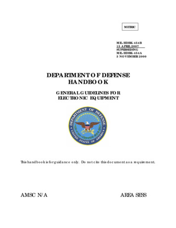
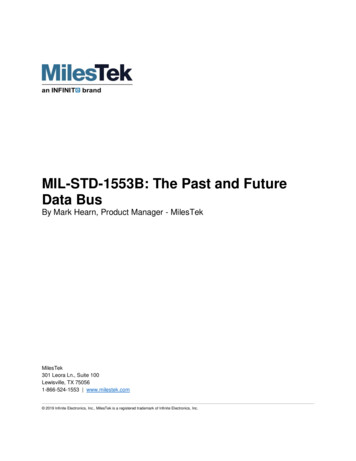
MlL-HDBK-155324 September19865.2.1.1.1liT response to command word All possible command words (65,536combinations)meeting the criteria of the paragraph on "Word validation" ofMIL-STD-1553shall be sent to the UUT.Mode commands tested in 5.2.1.5,5.2.2.1 or 5.2.2.4 may be omitted from this test since they are tested separately.Each command word shall be followed by the proper number of contiguous valid data words as definedin the paragraphon ''Message formats" ofMIL-STD-1553.Refer to table I for undefined mode commands.The associateddata may be either random or controlled, depending on the UUT requirements.The following sequence shall be executed for all combinations of command wordswhere the varying command word is sent as step 2.modeusedStep 1.Send a validlegal non-broadcastStep 2.Send the variablecommand wordnon-modecommandto the UUTto the UUT.Step 3. Send a transmit last command mode command to the UUT.(If thiscommand is not implemented, then a transmit status mode command shall beand the data word associated with transmit last command mode commandshall be deletedfrom the pass criteria.)The pass criteria given below is contingent on the type of commandcommands which cause the UUT to fail shall be de commands):a. Valid legal commands: step 1- CS; step 2- CS; step 3- CS and the dataword contains the command word bit pattern from step 2 (except for transmitlast command mode command where the data word contains the command word bitpattern from step 1).b.Validillegalcommands:(I) If illegal command detection option is implemented: step 1- CS;step 2- ME with no data words; step 3- ME and the data word contains the command wo d bit pattern from step 2.(2) If the illegalcommanddetectionoptionis not implemented:step 1- CS; step 2- CSj step 3- CS and the data word contains the command wordbit patcern from step 2.c. Invalid command (wrong RT address): step 1- CS; step 2- NR; step 3- CSand the data word contains the command word bit pattern from step 1.d. Undefined mode(4), if acceptable):commands(see table I)(1) step 1- CS; step 2- CS; step1.thecommand word bit pattern addressed to 2.data(2) step 1· CS; step 2- ME; stepword bit pattern(3)command wordaddressed(any single3- CS and the data word containsUUT from step data word containsword3ME containsand theto the UUT from step 2.step 1- CS; step 2- NRj step 3- CS and thebit pattern addressed to the UUT from step(4) step 1- CS; step 2- NR; step 3- ME and thecommand word bit pattern addressed to the UUT from step9set (1), (2), (3),the
MIL-HDBK-1S5324 September e codes.ASSOCIATEDNO1010110100011110000010000 CODE YES10010MODE10011 OOOIT/RDATA WORD-e. commandsmode commands):thatareconsidered(1) Legal commands: step 1- CS; step 2- NR; step 3- BCR andcontains the command word bit pattern from step 2.asvalidthe data(2)Illegal commands (if illegal command detection is implemented):step 1- CS; step 2- NR; step 3- BCR and ME and the data word contains thecommand word bit pattern from step 2.(3) Illegal commands(if illegal command detectionis not implemented):step 1- CS; step 2- NR; step 3- BCR and the data word contains thecommand word bit pattern from step 2.f.Iftherearenobroadcastcommandsthatcommands:step 1- CS; step 2- NR; step 3- CS andcommand word bit pattern from step 1.g. Undefined broadcast(2). (3) is acceptable):modecommands(see table I)(1) step 1- CS; step 2- NR; step 3- BCRthe command word bit pattern from step 2.containsareconsideredthe data wordand(2) step 1- CS; step 2- NR; step 3- ME andthe command word bit pattern from step 2.(any singlethe datawordBCRtheand(3) step 1- CS; step 2- NR; step 3- CS and the data wordcommand word bit pattern from step rd-the
MIL-HDBK-155324 September 1986.T-RT rea onae to command vorda.All possiblecommand words5.2.1.1.2(65,536combinationsmeetingthe criteriaof the paragraphon "Wordvalidation"of MIL-STD-1553 shallbe sent to the UUT
MIL-STD-1553B. For those remote terminals not required to meet Notice 2. Appendix C and D list the changes in this test plan for MIL-STD-1553B only and MIL-STD-1553B. Notice 1. These requirements shall apply to the terminal under test. when invoked in a specification or statement of work. 2.0 APPLICABLE DOCUMENTS 2.1 Standards MILITARY MIL-STD-1553