Transcription
SmartThermostatConnect with us online@ecobeefacebook.com/ecobeeWe’re here to helpsupport@ecobee.com 1.877.932.6233 2014 ecobee477 Richmond Street W, Suite 210Toronto, M5V 3E7, Canadaecobee is a registered trademark of ecobee inc.All rights reserved.InstallationManual
CONTENTSGetting Started2WelcomeTechnical SupportBefore You BeginHVAC System Compatibility InformationFCC Compliance StatementSpecifications223345Installing the ecobee Smart Thermostat7Installing the Equipment InterfaceWiring the Equipment InterfaceWiring DiagramsInstalling the Smart ThermostatConnecting the Smart Thermostatto the Equipment InterfaceConnecting PowerEquipment Interface Status LED78915161718Navigating the Smart Thermostat19Configuring the Installer Settings20Configuring the Installer SettingsInstallation WizardEquipmentThresholdsTest EquipmentSensorsSetting up the Remote Sensor InputsView Wiring DiagramContractor InfoReset Installation SettingsReset All SettingsPerforming a Hardware ResetConfiguring the Reminder AlertsAlerts2020202427272728282929292930Warranty31
GETTING STARTEDWelcomeThank you for supporting ecobee, the Smart Thermostatthat provides your customers with freedom and flexibilityin managing their home environment.The ecobee Smart Thermostat has been designedin partnership with HVAC contractors to ensure theinstallation process is simple and efficient. Thisstep-by-step Installation Manual will walk you throughall aspects of the installation.To ensure an on-going service relationship with yourcustomers, please register all of your ecobee SmartThermostats in your Contractor Portal.The ecobee TeamTechnical supportOur technical support team is available to answer yourquestions at 1.877-9-ecobee (1.877.932.6233), or viaemail at support@ecobee.com.2
1.ecobeeBefore You BeginEquipment DescriptionThis product is intended to be installed by trainedservice professionalsGas/Oil/Electric heating (up to three stages)YesHeat pump with auxiliary heat (up to four stages)YesThis manual explains the procedures for installing theecobee Smart Thermostat. Please read it carefully beforebeginning the installation.Geothermal Heat PumpYesDuel fuel systemsYesFor information on how to operate the ecobee SmartThermostat, please see the ecobee User’s Manual.Standard electric cooling (up to two stages)YesBoilersYesThe ecobee Smart Thermostat consists of two parts(see images below):Central humidifierYesCentral dehumidifierYes1. A Smart Thermostat to be mounted on thehomeowner’s wall.Heat Recovery Ventilator (HRV)YesEnergy Recovery Ventilator (ERV)Yes2. An Equipment Interface Module This should bemounted in the homeowner’s utility room andconnects to the heating, cooling and ventilationequipment.Sensors with dry contact outputsYesCaution: Disconnect electric power to the system beforeinstalling this product. Failure to do so could result inelectric shock and/or equipment damage.All wiring must conform to your local electrical code.Mercury Notice: This product does not contain mercury.If you are replacing a product that does containmercury please contact your local waste-managementauthority for disposal instructions. Do not discard theold product in the regular trash.2.HVAC System Compatibility informationecobee is designed to operate low-voltage heating andcooling systems. It is not designed for use with linevoltage or millivolt heating and cooling systems. ecobeesupports control of up to four heating stages and twocooling stages. It also supports control of humidifiers,dehumidifiers, heat-recovery ventilators andenergy-recovery ventilators.3Getting StartedApprovalsThis product was designed and built in accordance toRoHS directive 2002/95/EC and contains no hazardoussubstances as defined by this directive.Optional Power supply meets EPA C.E.C Level IV and E.CCoC No Load power Consumption requirements. It isalso safety approved to UL/cUL standards.FCC Compliance StatementThis equipment has been tested and found to complywith the limits for Class B digital devices, pursuantto Part 15 of the FCC Rules. These limits are designedto provide reasonable protection against harmfulinterference in a residential installation. This equipmentgenerates uses and can radiate radio frequency energyand, if not installed and used in accordance with theinstruction manual, may cause harmful interference toradio communications. However, there is no guarantee thatinterference will not occur in a particular installation.If this equipment does cause harmful interference toradio or television reception, which can be determinedby turning the equipment off and on, the user isencouraged to try to correct the interference by one ormore of the following measures:Getting Started4
Reorient or relocate the receiving antennaIncrease the separation between the equipmentand receiverConnect the equipment to an outlet on a differentcircuit from the receiverConsult the dealer or an experienced radio/TVcontractor for help.Wiring SpecificationsRefer to this table to determine maximum wire lengths allowed:Smart Thermostat to Equipment InterfaceSpecificationsTemperature rangesHeat: 45 – 79 F (7 – 26 C)Cool: 58 – 92 F (14 – 33 C)Display: 40 – 100 F (5 – 37 C)Sensitivity: /- 1 F (0.5 C)Equipment Interface Operating: -40o to 160oF (-40o to 70oC)Thermostat Operating: 32o to 130oF (0o to 55oC)Humidity RangeHumidify: 20 to 50% R.HDehumidify: 30 to 60% R.HDisplay: 0 - 90% R.HSensitivity: /- 2% R.H.Operating: 5 – 95% R.H non-condensingDimensionsThermostat: 5.5”W x 3.25”H x 1”D (139.5mm H x 82.5mmW x 25mm D)Equipment Interface: 4.6”W x 10”H x 1.3”D (118mm W x254mm H x 32mm D)PowerAC Transformer - 24 VAC - 3VA Minimum (not included)Battery – CR2032 – 3V lithium coin cell (included),Power Adaptor - #EB-PS-01 - 120V 50/60Hz to 12V DC 1A(not included)5Getting Started20 AWG22 AWG1250ft/380m790ft/240m500ft/150mEquipment Interface to heating/air equipmentWarning: Changes or modifications not expresslyapproved by ecobee Inc. could void the user’sauthority to operate the equipment.To satisfy FCC/IC RF exposure safety requirements, aseparation distance of 20 cm or more should be maintainedbetween this device and persons. To ensure compliance,operation at closer than this distance is not allowed.FCC ID: WR9EBSTATIC: 7981A-EBSTAT18 AWG18 AWG20 AWG22 AWG128ft/39m80ft/24m50ft/15mTerminal Description and Electrical RatingsTerminalDescriptionVoltageCurrent maxY1st stage cooling30V AC3AW (O/B)1st stage heating(or changeover)30V AC3AGFan30V AC3AW2(AUX)2nd stage heating(or 1st auxiliary heat)30V AC3AR/HHeat transformer return30V AC3AR/CCool transformer return30V AC3AACC11st accessory relay30V AC3AACC1r1st accessory relay return30V AC3AACC22nd accessory relay30V AC3AACC2r2nd accessory relay return30V AC3AACC33rd accessory relay30V AC3AACC3r3rd accessory relay return30V AC3AIN1 Input 1 Dry contact onlyDry contact onlyIN1-Input 1 -Dry contact onlyDry contact onlyIN2 Input 2 Dry contact onlyDry contact onlyIN2-Input 2-Dry contact onlyDry contact only 12v12V DC power to Thermostat8-14V DC600mAGNDGND to Thermostat--D Data communication line--D-Data – communication line--Getting Started6
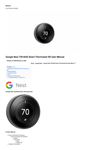
Installing theSmart ThermostatThere are five steps to installing the ecobee Smart ThermostatStep 1: Install the Equipment Interface.Step 2: Wire the Equipment Interface.Step 3: Install the Smart Thermostat.Step 4: Connect the Smart Thermostat to theEquipment Interface.Step 5: Power up both devices.Installing the Equipment InterfaceTo install the Equipment Interface:1. In the homeowner’s utility room or basement, selecta suitable location either on a wall or on the cold airreturn plenum. Make sure the surface is relatively flatand, if you are using a power adaptor, make sure there isan electrical outlet within five feet of where you plan tomount the device.2. Remove the front cover of the Equipment Interface. Ifnecessary, Insert a flat-head screwdriver into one of theslots as shown below, and gently twist the screwdriver.Mounting holes indicated with solid color4. Move the back of the enclosure out of the way andmake the holes where indicated in step 3. The mountingholes can accommodate a #6 pan-head screw.5. Use drywall plugs or other screw anchors (notincluded) to ensure the Equipment Interface can bemounted securely.6. Fasten the backplate to the wall using the appropriatescrews (not included).Wiring the Equipment InterfaceTo wire the Equipment Interface:1. Disconnect the power to the heating and airconditioning equipment.2. Disconnect the wires going to the existing Thermostat.Insert a screwdriver into one of the two slots and twist gently3. Place the back of the enclosure on the intendedmounting surface and use it as a template to mark thelocation of the mounting holes, as shown below.7Installing The Smart Thermostat3. Using the wiring diagrams on pages 9-14, connectthe heating or air conditioning equipment to theEquipment Interface.4. Do not apply power until you have installed andconnected the Smart Thermostat. (see instructions onpage 15-18)5. Do not install the front cover on the EquipmentInterface at this point.Installing The Smart Thermostat8
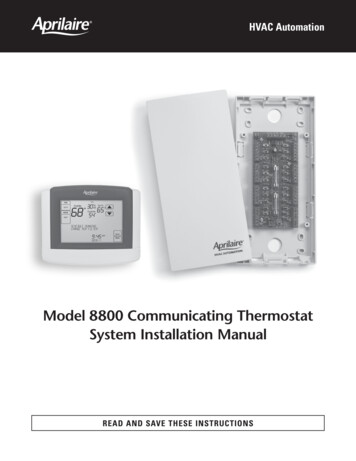
Wiring DiagramsBelow are the Equipment Interface Terminal LabelsPlease take note that there is a factory installed jumperbetween R/H and R/C.24 VacTwo Stage Heat/ Single Stage Cool With 3 AccessoriesPowerEquipment InterfaceSystemLineCommunicationsYW O/BGW2 AUXR/HYW O/BGW2 AUXR/HR/CNCNCACC1ACC1rIN2IN2 R/CHRVACC2ACC2rACC3ACC3rIN1IN1 D-DehumidifierHumidifierD FurnaceAir ACC1r24VCACC2ACC2rACC3ACC3rDehumidifier24VCGND 12VSingle Stage Heat/Cool With 3 AccessoriesTwo Stage Heat/Cool With 2 AccessoriesDual Stage Heat, Single Stage Cool with Three AccessoriesNOTE Non Powered Accessories will require a jumper from RH RC to ACC1, ACC2, ACC3 for a 24V feed.factory installed jumper.Equipment InterfaceYW O/BGW2 iagram indicates 24V humidifier terminal. If your furnace control board does not have this, you must use a 110V/24V step down transformer.Equipment InterfaceFurnaceAir Conditioner24V24VYW O/BGW2 CC3ACC3rComp2Dehumidifier24VHumidifierAir CC1rHRVACC2ACC2rACC3ACC3r24VCCSingle Stage Heat/Cool with Thrre AccessoriesNOTEfactory installed jumper.Non Powered Accessories will require a jumper from RH RC to ACC1, ACC2, ACC3 for a 24V feed.Diagram indicates 24V humidifier terminal. If your furnace control board does not have this, you must use a 110V/24V step down transformer.9Installing The Smart ThermostatDual Stage Heat/Cool with Two AccessoriesNOTEIndicates jumper. Non Powered Accessories will require a jumper from RH RC to ACC1, ACC2, ACC3 for a 24V feed.factory installed jumper.indicates a jumper. Non-powered accessories require a jumperfrom RH / RC to ACC1, ACC2, ACC3 for a 24V feed.Diagram indicates 24V humidifier terminal. If your furnace control board does not have this, you must use a 110V/24V step down transformer.Installing The Smart Thermostat10
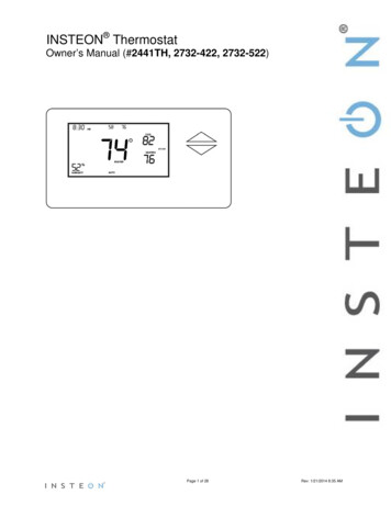
Three Stage Heat 2 Stage Cool With 1 AccessoriesEquipment InterfaceFurnaceY1W1GW2RY2W3HumCYW O/BGW2 AUXR/HR/C3rd StageHeat2nd StageCoolHumidifierACC1ACC1rTwo Stage Heat/Cool With 1 Stage Auxiliary Heat (Duel Fuel) with 2 AccessoriesEquipment InterfaceAir ConditionerY1Y2RCYW O/BGW2 erOW2W1Y/Y2GRCR/CAux HeatStage 2HumidifierNOTEOW2YRCYW O/BGW2 AUXR/HR/CHumidifierComp2HumidifierC11Installing The Smart Thermostat24VCY1W1GW2RY2HumCHeat CC3rDual Stage Heat/Cool, Dual Stage Auxiliary Heat with One AccessoryNOTESingle Stage Heat/Cool , Dual Stage Auxiliary Heat with HumidiferIndicates jumper. Non Powered Accessories will require a jumper from RH RC to ACC1, ACC2, ACC3 for a 24V feed.factory installed jumper.HRVDiagram indicates 24V humidifier terminal. If your furnace control board does not have this, you must use a 110V/24V step down transformer.Equipment InterfaceFurnaceC 110VCONFIGURE ACC2 - Emerg Heat 2 ACC3 - HumidifierCACC2ACC2rACC3ACC3rDual Stage Heat/Cool, Single Stage Auxiliary Heat with Two Accessories1-Speed Heat Pump24V24VIndicates jumper. Non Powered Accessories will require a jumper from RH RC to ACC1, ACC2, ACC3 for a 24V feed.factory installed jumper.Aux HeatStage 2C24VY2RCTwo Stage Heat/Cool Two Stage Auxiliary Heat (Duel Fuel) With One CC1rThree Stage Heat, Two Stage Cool with One AccessoryIndicates jumper. Non Powered Accessories will require a jumper from RH RC to ACC1, ACC2, ACC3 for a 24V feed.factory installed jumper.YW O/BGW2 AUXR/HYWGRHumCHumidifierCHRVDiagram indicates 24V humidifier terminal. If your furnace control board does not have this, you must use a 110V/24V step down transformer.Equipment InterfaceFan CoilHeat Pump24V1 Stage Heat/Cool With 2 Stage Auxiliary Heat (Duel Fuel) With Humidifier AccessoryNOTEFurnaceIndicates jumper. Non Powered Accessories will require a jumper from RH RC to ACC1, ACC2, ACC3 for a 24V feed.factory installed jumper.indicates a jumper. Non-powered accessories require a jumperfrom RH / RC to ACC1, ACC2, ACC3 for a 24V feed.Diagram indicates 24V humidifier terminal. If your furnace control board does not have this, you must use a 110V/24V step down transformer.Installing The Smart Thermostat12
Two Stage Furnace (Carrier 58MVB) With Two Stage Heat Pump (Duel Fuel)Equipment InterfaceFurnaceW2Y1W/W2Y/Y2GRYW O/BGW2 AUXR/HR/CAux HeatStage 2Comp2DehumidifierHeat ACC2rACC3ACC3rHumidastatDual Transformer – Dual Stage Cooling With BoilerDual Transformer – Single Stage Cooling With BoilerDual Stage Furnace with Dehumidifier and Two Stage Heat PumpNOTEIndicates jumper. Non Powered Accessories will require a jumper from RH RC to ACC1, ACC2, ACC3 for a 24V feed.factory installed jumper.Equipment InterfaceDiagram indicates 24V humidifier terminal. If your furnace control board does not have this, you must use a 110V/24V step down transformer.Equipment InterfaceYW O/BGW2 AUXR/HFan CoilYGRCR/CFan CoilAir ConditionerAir ConditionerBoilerRCWY1Y2GRCYW O/BGW2 AUXR/H24VCComp ACC3rACC2ACC2rACC3ACC3rDual Stage Cooling with BoilerSingle Stage Cooling with BoilerNOTENOTERemove factory installed jumper13Installing The Smart Thermostatfactory installed jumper must be removed for this configuration.Non Powered Accessories will require a jumper from RH RC to ACC1, ACC2, ACC3 for a 24V feed.factory installed jumper must be removed for this configuration.Non Powered Accessories will require a jumper from RH RC to ACC1, ACC2, ACC3 for a 24V feed.indicates a jumper. Non-powered accessories require a jumperfrom RH / RC to ACC1, ACC2, ACC3 for a 24V feed.Installing The Smart Thermostat14
Installing the Smart ThermostatThe ideal location for the Smart Thermostat isapproximately five feet (1.5m) above floor level in themain living area.Do not install the Smart Thermostat:Close to sources of heat such as incandescent lightsor heating/cooling registers.In direct sunlight.On exterior, non-insulated or poorly insulated walls.In the kitchen or other areas of potentially high heatand/or humidity.In an area that could restrict air flow.To Install the Smart Thermostat:1. Remove the front cover of the Smart Thermostat,insert a flat-head screwdriver into one of the slots asshown below and gently twist the screwdriver.4. Move the backplate out of the way and make holeswhere indicated in step 3. The mounting holes canaccommodate a #6 pan-head screw.5. Use drywall plugs or other screw anchors (notincluded) to ensure the Smart Thermostat can bemounted securely to the wall.6. Fasten the backplate to the wall using the appropriatescrews (not included).Connecting the Smart Thermostat tothe Equipment InterfaceOnly four wires are needed to connect the SmartThermostat to the Equipment Interface. If you arereplacing a Thermostat, you can use the existing wiring.Note: Ensure any unused wires do not have exposedbare copper conductors.Follow these steps to connect the Smart Thermostat to theEquipment Interface:1. Connect the wires between the Smart Thermostat andEquipment Interface as shown below.DD GNDEquipmentInterface 12VD-Insert screwdriver into one of the two slots and twist gently2. Place the Smart Thermostat backplate on the wall.Make sure that any existing wires can be insertedthrough the opening for the wiring.3. Using the backplate as a template, mark the locationof the mounting holes on the wall as shown below.D-Installing The Smart ThermostatThermostatWiring from Smart Thermostat to the Equipment Interface2. Attach the front cover of the Smart Thermostat to thebackplate. Ensure the four pins on the circuit board matewith the terminal block on the backplate as shown below.D GND 12VThe solid color indicates mounting holes15D GND 12VReplace the front cover ensuring the pins meet the terminalsInstalling The Smart Thermostat16
Equipment Interface Status LED Note the small clipson the edge of thebattery encasing.The Equipment Interface has four LEDs to display thestatus of the system.Slide the battery under the contacts and push down firmlyPush down on thebattery firmly untilit snaps into place.Slide the batteryUNDER the clips.If you’ve wired the system correctly, only the Power LEDshould be on.The Thermostat comes with a factory installed, coin cellbattery. When replacing the battery ensure the side ofthe battery is facing out and the battery contacts remainin the upright position (not bent underneath the battery).The battery should snap in easily.PowerSystemLineCommunicationConnecting PowerLED arrangementOnce you’ve completed the wiring of the SmartThermostat and Equipment Interface, you can applypower to the Equipment Interface and restore powerto the heating and air conditioning equipment.There are two methods of powering the SmartThermostat. You can power it directly from a 24VACsource capable of at least 3VA.24 VacThe LEDs operate as follows:Power This LED monitors the power supply of theEquipment Interface.LED ONPower is connected to the EquipmentInterface and is within the appropriatevoltage range.LED OFFPower is disconnected or has droppedbelow 9V.System This LED monitors the operation of theEquipment Interface.24Vac 3VA minHard-wired 24 VAC optionThe second method requires the optional 120V to 12Vdcpower adaptor. Plug the power supply into a standardelectrical outlet and plug the barrel connector into theEquipment Interface.LED ONThere is a fault with the Equipment Interface.LED OFFThe equipment interface is operational.Line This LED monitors the power supplied to the SmartThermostat from the Equipment Interface.LED ONThe voltage at the 12V and GND terminalhas dropped below 7V.LED OFFAdequate power is being supplied to theSmart Thermostat.Communication This LED monitors the communicationPlug the adaptor into the Equipment Interface17Installing The Smart Thermostatbetween the Smart Thermostat and the EquipmentInterface (i.e., the D and D- terminals).LED ONThe Equipment Interface and Smart Thermostatare not communicating with each other.LED OFFThe two devices are communicating properly.Installing The Smart Thermostat18
Navigating theSmart ThermostatConfiguring theSmart ThermostatOnce the Smart Thermostat and Equipment Interfaceare powered up and working correctly, you can beginconfiguring the system.Configuring the Installer SettingsThe Smart Thermostat uses touch screen technology, so it’seasy to navigate – just tap the icons, buttons and lists.Note: To prevent damage to the touch screen, never use a sharpobject such as a pen.When the screen shows a list setting an arrow on the right,it indicates there are more than two options to choose from.If there is no arrow, then the list item only has two options.Toggle between options by pressing the list item.In the various screens, you have three navigation choices:Press Done to save changes and move to the next screen.Press Cancel to go back to the previous screen withoutsaving changes.At any time, press the Home button (found on theright-hand side of the touch screen). This cancels anyaction and takes you back to the home screen.If you need to enter data in the form of text, you will bepresented with a keyboard.Pressing the Caps key will allow you to enter capitalletters; pressing the 123@ key will change the letters tonumbers or commonly used symbols.Installer Settings let you configure the settings relatedto the various devices (such as a furnace, air conditioner,humidifier, dehumidifier or ventilator) that are connectedto the Equipment Interface.To prevent accidental modifications to these settingsyou can enable a 4-digit installer code. This code ispre-programmed to 3262 and can be enabled in theThresholds option menu.To configure the installersettings:From the Homescreen, press More.Press Settings andselect InstallationSettingsInstallation WizardThe Installation Wizard takes you step-by-step througha series of choices regarding the HVAC equipmentintended to be connected to the Equipment Interface.Simply answer the questions accordingly and press Nextto advance to the next screen. Once completed youwill be shown a diagram of the wiring connections thatreflects the choices made during the wizard process. Youcan press Back to go back and make any changes. Onceyou are satisfied with the setup, press Done.EquipmentThe equipment setting will allow you to manuallyconfigure the various devices that are connected tothe Equipment Interface.Heat PumpThis section allows you to enable and configure up toa 2 stage heat pump. If a second stage is required youmust configure an Accessory relay to control that stageGeothermal/Ground Source Heat pump If you selectYes, this tells the system a geothermal or ground sourceheat pump is being controlled. This helps the Thermostatdetermine optimum performance and default settings.If you select NO, the system will optimize for an air-to-airheat pump.O/B Energize on Cool If you choose Yes, the reversingvalve output (O/B terminal) will activate when there is acall for cooling. If you select No, the relay will energizewhen there is call for heat.19Navigating The Smart ThermostatConfiguring The Smart Thermostat20
Min Cycle Off Time Enables you to configure thecompressor off time between cycles. This is adjustablefrom 240 - 900 Seconds.Heat Stages Allows you to configure up to 3 stages ofheat. If you require a third stage, you must configurean accessory relay to control that stage.Min Outdoor Temp Allows you to set the minimumoutside air temperature at which the compressor willbe disabled. This performs two functions: You can setit to prevent the compressor from going on whenthe outdoor temperature is too low, thus resulting indamage to the compressor. You can also set this value todetermine when you want the auxiliary heat (if installed)to engage to help meet the set temperature. Thetemperature range is adjustable from 0 F (-17.8 C) - 65 F(18.3 C) or can be completely disabled. You will need aninternet connection for this feature to operate properly.Heat Fan Control This option allows you to determineif the system fan is controlled by the system duringheat cycles, or if the Thermostat is required to controlthe fan. Normally the HVAC system controls the fanduring heat cycles.Allow Heat Pump/Auxiliary Heat to Run SimultaneouslyIf you select Yes and there is a source of auxiliaryheat, it will turn on in addition to the heat pump. Theheat pump will be energized for the first 30 minutes.If, after 30 minutes, the set point has not been met,the auxiliary heat will be energized to assist the heatpump in meeting the load.If you select no, the heat pump will be energized for upto 2 hours. If after 2 hours the set point has not beenmet, the Thermostat will shutdown the heat pump andenergize the auxiliary heat to meet the set point. Thisoption should also be used for installation where theheat pump evaporator coil is downstream from thesource of auxiliary heat.Furnace (Auxiliary Heat)Allows you to enable and configure up to a 3-stageconventional heat source. If you have selected Heatpump as your primary source, this feature will allow youto configure the auxiliary heat connected to the system.Furnace Type Allows you to configure the type of furnace connected. This allows the Smart Thermostat tooptimize its algorithms based on the type of fuel andtypical characteristics of the chosen system. Choosethe option that best represents the type of heatingsystem installed.21Configuring The Smart ThermostatAir ConditionerAllows you to enable and configure up to 2 stages of airconditioning. If you require a second stage, you mustconfigure an accessory relay to control that stage.Staging Method of OperationThe ecobee Smart Thermostat uses a unique methodfor staging for multi-stage heating or cooling. It usesa combination of intelligent algorithms and pastperformance to determine when to activate the stages.When there is a call for heat or cool, the system computeshow long it would take for the system to reach the desiredset point in stage 1, stage 2 or stage 3 accordingly. It willdetermine the highest stage at which a minimum of 10minutes of run time is required. It will then automaticallystart the system at that stage (ie if it calculates that it willtake 15 minutes at stage 2 but only 7 minutes at stage 3,the system will immediately turn on stage 2 to meet theset point). If the calculation indicates to start at stage 1,and it takes more than 10 minutes to reach the set point,it will automatically engage stage 2. If stage 2 runs formore than 10 minute without reaching the set point it willactivate stage 3. A minimum run time of 10 minutes is usedto ensure that proper circulation throughout the systemand that minimum cycle times are maintained. For heatpumps with auxiliary heat, the operation of the auxiliaryheat will depend on the configuration of the Allow HeatPump/Auxiliary Heat to Run Simultaneously.Accessory relaysAccessory relays are generic relays that can be configuredto control the following;Heat Stage 3 Select this option when the Thermostatis required to control a 3-stage conventional heatingsystem. Connect the third stage (or W3) contact to thisaccessory relay.Configuring The Smart Thermostat22
Auxiliary Heat Stage 2 Select this option when theThermostat is required to control a heat pump systemwith 2 stages of Auxiliary heat. Connect the secondstage of the auxiliary heat to this relay.Compressor/AC Stage 2 Select this option when theThermostat is required to control either a 2 stage heatpump or a 2 stage air conditioner. Connect the Y2terminal of the system to this relay.Humidifier Select this option when the Thermostatis required to control a humidifier. When this option isselected you will also be able to configure the following:Humidify only while heating If Yes is chosen, thesystem will activate this relay when the currenthumidity is below the humidity set point and thereis a call for heat.If No is chosen the system will activate this relay andthe system fan when the current humidity is belowthe humidity set point. This is designed to supportsteam type humidifiersWindow Efficiency To optimize the frost controlfeature of this system the system needs to know theefficiency ratio of the windows within the area beingcontrolled. Options are Low, Medium and High.NEW Min Runtime Delta Determines how far fromthe set point, the system will maintain to reduce shortcycling of the equipment.Dehumidifier On a call for cool, if the current humidityis above the set point, this relay will be activated.When this option is selected you will also be able toconfigure if you wish to enable the fan during thedehumidification cycle. Choose yes if you are usingthe air conditioning system to dehumidify, choose Noif you are using a standalone dehumidification systemthat independently controls the system fan.NEW Min Runtime Delta Determines how far fromthe set point, the system will maintain to reduce shortcycling of the equipment.NEW Dehumidify in Heat Mode Allows you tocontrol the dehumidification even when the systemis in heat mode.23Configuring The Smart ThermostatNEW Dehumidifier Active Allow you to configure ifthe active stat of this relay is open or closed.Ventilator Activated when the user engages VentilatorMax from the Details screen. The system fan will alsoturn on when Ventilator Max is engagedThresholdsThis section will allow you to configure the varioustemperature or time thresholds associated with theheating and cooling equipment. You must configure therequired equipment first before setting the thresholds,and only the application thresholds will be shown (i.e.if no air conditioner is configured, you will not see theoptions related to air conditioners).Allow Auto Heat/CoolEnable this option to allow the user to select autochange-over as a system mode.Heat/Cool Min DeltaThe minimum difference between the heat mode settemperature and the cool mode set temperature whenthe system mode is in auto change-over.Compressor SettingsMin Cycle Off Time Allows you to configure thecompressor off time between cycles. This ensures thecompressor does not short cycle which could affectthe operating life of the system. This is adjustablefrom 240 - 900 seconds.Min Outdoor Temp This section allows you to setthe minimum outside air temperature at which thecompressor will be disabled. This performs twofunctions: You can set it to prevent the compressorfrom going on when the outdoor temperature is toolow, thus resulting in damage to the compressor.You can also set this value to determine when youwant the auxiliary heat (if installed) to engage to helpmeet the set temperature. The temperature range isadjustable from 0 F (-17.8 C) - 65 F (18.3 C) or canbe completely disabled. You will need an in
There are five steps to installing the ecobee Smart Thermostat Step 1: Install the Equipment Interface. Step 2: Wire the Equipment Interface. Step 3: Install the Smart Thermostat. Step 4: Connect the Smart Thermostat to the Equipment Interface. Step 5: Power up both devices. Installing the Equipment Interface To install the Equipment Interface: 1.