Transcription
Lecture 7: Introduction to HFSS-IE2015.0 ReleaseANSYS HFSS for Antenna Design1 2015 ANSYS, Inc.May 6, 2015Release 2015.0
HFSS-IE: Integral Equation Solver Introduction HFSS-IE: Technology An Integral Equation solver technology in the HFSS desktop A 3D Method of Moments (MoM) Integral Equation techniqueE (r ) j k02 J (r ) G (r r ) dS k0S– Efficient Solution Technique for Open Radiation and Scattering Analysis Only surfaces are meshed and solved– Hybrid IE and FEM solution can be used to leverage most efficient techniques from either method simultaneouslyPhysical optics, high frequency solver also included within HFSS-IE design type HFSS-IE: Applications 2Antenna design, antenna placement, Radar Cross Section, S-parameter extraction, EMI/EMC Analysis, Efficient analysis ofelectrically large structures 2015 ANSYS, Inc.May 6, 2015Release 2015.0
Adaptive mesh HFSS-IE: Advantage Automated results with accuracy Effective utilization of automated adaptive meshing technique from HFSS to ensure accuracyEmploys Adaptive Cross Approximation (ACA) technique– Compression is independent of mesh creation leads to efficient results with minimal userinteraction. Robust and invariant to problem description. Employs Multilevel Fast Multipole Method (MLFMM)– Decomposes geometry into boxes and then solves the fields based on a physicsdecomposition. Efficient for models with low complexity and geometric dynamic range.Utilization of results from HFSS or HFSS-IE as a linked source excitation HFSS-IE: User Interface Implemented as a design type in the HFSS desktop– Shares same modeler interface and similar analysis setup– Minimal user training required for existing users of HFSS3 2015 ANSYS, Inc.May 6, 2015Release 2015.0
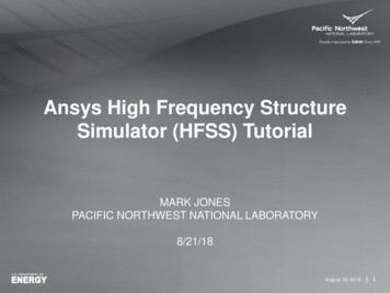
Choice of Solution Methods Solution to geometryusing either FEM or IEAntenna Geometry Both solution yield thesame results FEM solution requires an air volume surrounding antenna,IE solution does notIntegral equation solutionwould be most efficient whengeometry is primarily metalFinite Element MethodIntegral EquationHFSS-IE ModelHFSS Model Efficient solution technique for open radiation and 4scatteringCurrents solved only on surface meshEfficiency is achieved when structure is primarily metal 2015 ANSYS, Inc.May 6, 2015 Efficiently handles complex material and geometriesVolume based mesh and field solutionsFields are explicitly solved throughout entire volumeRelease 2015.0
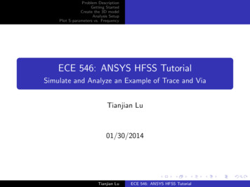
HFSS-IE Solver ExamplesRCS of Fighter Aircraft @ 2GHz130λ183λSolverMemory (GB)CPUHFSS-IE84.40.5 hoursAntenna Placement on CommercialAircraft @ 2.45GHz5 2015 ANSYS, Inc.May 6, 2015SolverMemory (GB)CPUHFSS-IE94.32 hoursRelease 2015.0
Adaptive mesh HFSS-IE: Advantage Automated results with accuracy Effective utilization of automated adaptive meshing technique from HFSS to ensure accuracyEmploys Adaptive Cross Approximation (ACA) technique– Compression is independent of mesh creation leads to efficient results with minimal userinteraction Employs Multilevel Fast Multipole Method (MLFMM)– Decomposes geometry into boxes and then solves the fields based on a physicsdecompositionUtilization of results from HFSS or HFSS-IE as a linked source excitation HFSS-IE: User Interface Implemented as a design type in the HFSS desktop– Shares same modeler interface and similar analysis setup– Minimal user training required for existing users of HFSS6 2015 ANSYS, Inc.May 6, 2015Release 2015.0
HFSS-IE Solvers HFSS IE Solver: ACA Solver: Is an algebraic method without physics consideration MLFMM Solver: MLFMM solver decomposes geometry into boxes Fields in these boxes are solved based on a physicsdecomposition 7Factors that influence efficiency of MLFMM relative to ACA: Feature size variation– High complexity and geometric dynamic range causelonger simulation Aspect ratio of bounding box of model– High aspect ratio results in longer simulationIn general ACA is more robust and invariant to problemdescription When in doubt use ACA 2015 ANSYS, Inc.May 6, 2015Release 2015.0
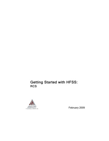
HFSS-IE SolversBoeing X-48 Blended Wing Body (BWB)361 incident angle in Phi@ 150 MHz, 0.9M matrix unknowns ACA PerformanceTime: 2:28:15Memory: 97.3 GB MLFMM PerformanceTime: 1:20:39Memory: 51.7 GB8 2015 ANSYS, Inc.May 6, 2015Release 2015.0
Guidelines for Choosing IE SolverGeometric/Mesh Complexity*Low - MediumHighACAAspect Ratio of Bounding Box 100ACA 100MLFMM* Automatic adaptive meshing for accuracy can result in large elements variation. An example couldbe a small antenna on an aircraft9 2015 ANSYS, Inc.May 6, 2015Release 2015.0
HFSS-IE, Physical Optics Solver Introduction Asymptotic solver for extremely large problems––––Included in HFSS-IESolves electrically huge problemsCurrents are approximated in illuminated regions Set to zero in shadow regionsNo ray tracing or multiple “bounces” Target applications:––Large reflector antennas and antenna placementRCS of large objects such as satellites Option in solution setup for HFSS-IE. Sourced by incident wave excitations– Plane waves or linked HFSS designs as a sourceRecieveScattererJ 2nxHincSource10 2015 ANSYS, Inc.May 6, 2015Release 2015.0
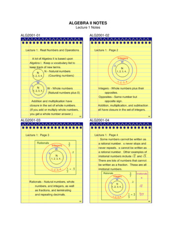
Physical OpticsPhysical OpticsFull Wave SolutionIncident WaveFull Wave SolutionPhysical Optics SolutionSolution @ HighFreq.Total RAM(GB)Elapsed Time(sec)Full Wave (HFSS-IE)1.487Physical Optics0.114RCS of PEC Sphere Highlights capabilities and limitation of physical optics Creeping wave effects not accounted for by PO When electrical size of sphere becomes large, full wave solution converges with physical optics solution11 2015 ANSYS, Inc.May 6, 2015Release 2015.0
Fighter Aircraft RCS using PO18GHz10GHzIncident Wave15.15 meter910 λ @ 18GHzFront ViewBlue – 18GHzRed – 10 GHz10.325 meter620 λ @ 18GHz4.19 meter252 λ @ 18GHzTop View12 2015 ANSYS, Inc.May 6, 2015Mesh #RAMElapsed Time10GHz5.03 million15.4 G27.5 minutes18GHz16.19 million50.6G174.5 minutesRelease 2015.0
HFSS-IE: Offers Advanced Features for Antenna Design Advanced solver technology ACA Solver robust Method for Efficient Solution MLFMM solver efficient for structures with low complexity New in R16 Hybrid FEM-IE solver takes advantage of strengths from both FEMand IE technologies Advanced Functionally Layered Impedance Boundary Condition Spatially Dependent Boundary Conditions New in HFSS 2014 Data-Link Source Excitations HFSS to HFSS-IE HFSS-IE to HFSS-IE New in HFSS 2014 High Loss Impedance Boundaries New in HFSS 2014 Anisotropic Impedance Boundary New in HFSS 2014 Curvilinear Mesh Elements New in HFSS 2014 High Performance Computing Scalable Multi-Threading Distributed Parametric and Frequency Sweeps Distributed meshing for hybrid solutions Distributed memory solution for large scale simulations Hybrid solution supports distributed FE-BI and IE-Regions Output quantities– Network Parameters– Antenna trace characteristics (Beamwidth, SLLs)– Near fields and far fields Design automation– Parametric modeling– Parametric sweeps– Optimizations– Sensitivity and statistical analysisNew in HFSS 2014 13Hierarchical distributed solutions New in HFSS 2014 2015 ANSYS, Inc.May 6, 2015Release 2015.0
This page intentionally left blank14 2015 ANSYS, Inc.May 6, 2015Release 2015.0
- Sensitivity and statistical analysis HFSS-IE: Offers Advanced Features for Antenna Design Advanced solver technology ACA Solver robust Method for Efficient Solution MLFMM solver efficient for structures with low complexityNew in R16 Hybrid FEM-IE solver takes advantage of strengths from both FEM and IE technologies