Transcription
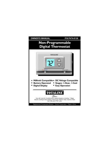
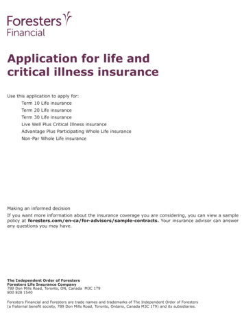
OWNER'S MANUALMODEL P474-0140Non-ProgrammableDigital ThermostatHEAT PUMP THERMOSTAT2 HEAT, 1 COOLTOTALINE72emergencyaux.heatnormalenergy saveFan On Fan AutoHeat Off CoolMillivolt CompatibleBattery or SystemPoweredDigital DisplayDC Voltage CompatibleStages: 2-Heat, 1-CoolEasy OperationTOTALINEStarReplacement Components Division - Carrier Corporation
OWNER'S MANUALMODEL P474-0140ContentsPage #Safety WarningsFront PanelDisplayNormal OperationAux HeatPreparationRemove Old ThermostatBattery ReplacementWire ConnectionsTest OperationTroubleshootingWarrantyPage 2
OWNER'S MANUALMODEL P474-0140Safety WarningsP/N P474-0140CAUTIONFollow Installation Instructions carefully.DISCONNECT POWER TO THE HEATER AIR CONDITIONER BEFORE REMOVINGTHE OLD THERMOSTAT AND INSTALLINGTHE NEW THERMOSTAT.WARNINGCAUTIONThe two AA alkaline batteries must be replaced at leastonce every 12 months to ensure properoperation. The Low Battery icon (fig. 1) willappear on the display when it is time toreplace the batteries. If the thermostat isFIG. 1connected to 24v power, the batteries shouldstill be installed, but are not required.Whenis displayed the batteries must be replacedimmediately. The manufacturer cannot be liable forimproper operation of the thermostat if the batteries arenot immediately replaced.Annual battery replacement is especially critical inlocations subject to freezing temperatures. Thethermostat will be unable to turn on the heating systemif the batteries are exhausted.This device complies with Part 15 of the FCC rules.Operation is subject to the following two conditions:(1) This device may not cause harmful interference, and (2)this device must accept any interference received, includinginterference that may cause undesired operation.Replacement Components DivisionPage 3Carrier Corporation 03/07
OWNER'S MANUALMODELP474-0140DIGITALTHERMOSTATFront PanelDISPLAYAUX HEATINDICATORTOTALINE72Heat Off Coolemergencyaux.heatnormalenergy saveUP & DOWNBUTTONSFan On Fan AutoAUX HEATSWITCHEmergencyMODE SWITCH FAN SWITCH NormalHeat, Off or Cool On or AutoLockoutPage 4
OWNER'S MANUALMODELP474-0140DIGITALTHERMOSTATDisplay78 74SET TEMPCurrent room temperature.If the UP or DOWN button is pressed the thermostatwill show the Set Temp indicator. When Set Temp isdisplayed you may use the UP or DOWN button toadjust the desired room temperature.NOTE: After five seconds with no button presses thethermostat will revert back to show the currentroom temperature.Page 5Page 5
OWNER'S MANUALMODELP474-0140DIGITALTHERMOSTATNormal OperationTOTALINE72Heat Off Coolemergencyaux.heatnormalenergy saveUP & DOWNBUTTONSFan On Fan AutoMODE SWITCH FAN SWITCHHeat, Off or Cool On or AutoOperationSelect Heat or Cool with the Mode Switch.Normally leave the fan switched to Fan Auto.In Fan Auto, the fan will turn on only with a heator cool demand. When Fan On is selected, thefan will run continuously.Adjust the desired set temperature with theUP and DOWN buttons.Page 6
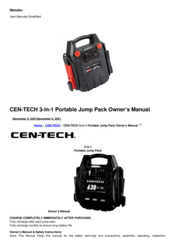
OWNER'S MANUALMODEL P474-0140Aux HeatTOTALINE72Heat Off Coolemergencyaux.heatnormalenergy saveFan On Fan AutoAux Heat Indicator - This LEDwill illuminate when thethermostat has energizedAux Heat.* (W2 terminal)*The LED will only turn on when thethermostat is powered from the HVACSystem. The cost of operating ElectricStrip Heat (Aux Heat) is normally significantly more expensive than the cost ofoperating Heat Pump.AUX HEATSWITCHOperationSwitchEmergencyNormalEnergy SaveEmergency - Disables all compressorfunctions** and energizes only AuxHeat to satisfy the heat demand.Normal - Aux Heat is allowed to run, if necessary,along with the heat pump to satisfy theheat demand.Energy Save - Aux Heat will never turn onregardless of the heat demand.** When the Aux Heat Switch is in the Emergency position the compressor will alsobe locked out during cooling operation.Page 7
OWNER'S MANUALMODEL P474-0140PreparationStep #1 PreparationTOTALINE72Fan On FanAutoHeat Off CoolProper installation of the thermostat will beaccomplished by following these stepby step instructions. If you are unsureabout any of these steps, call a qualifiedtechnician for assistance.These tools will be required:TOTALINE72Fan On FanAutoHeat Off CoolFlat BladeScrewdriverTOTALINE72Fan On FanAutoHeat Off CoolTOTALINE72Fan On FanAutoHeat Off CoolTOTALINE72Heat Off CoolFan On FanAutoWire cutter& StripperMake sure your Heat Pump is workingproperly before beginning installation ofthe thermostat.Carefully unpack the thermostat.Save the screws and instructions.Turn off the power to the Heat Pump atthe main fuse panel.Page 8
OWNER'S MANUALMODEL P474-0140Remove & ReplaceOld ThermostatTOTALINE72FanOn FanAutoHeat Off CoolTOTALINE72FanOn FanAutoHeat Off CoolTOTALINE72FanOn FanAutoHeat Off CoolTOTALINE72Heat Off CoolFanOn FanAutoRemove the cover of the old thermostat.If it does not come off easily check forscrews.Loosen the screws holding the thermostatbase or subbase to the wall, and lift away.Disconnect the wires from the oldthermostat. Tape the ends of the wiresas you disconnect them, and mark themwith the letter of the terminal for easyreconnection to the new thermostat.Keep the old thermostat for referencepurposes, until your new thermostat isfunctioning properly.Page 9
OWNER'S MANUALMODEL P474-0140Battery ReplacementThe top of the thermostat housing has two screwdriver slots to assist in separating theSCREWDRIVERSLOTSthermostat front from the sub-base.To pull the housing apart, insert a small blade screwdriver into the slot and rotate 90 . This will releasethe top housing snaps.Repeat this procedure in the other screw driver slot.Separate the thermostat front from the sub-base bypulling the top forward until the pins release, and thenlift the bottom out.Next PageThe batteries must be replacedimmediately when the thermostatdisplays the low battery icon (fig.1).Page 10FIG. 1
OWNER'S MANUALMODEL P474-0140Battery ReplacementRemove the old batteries and replace with new AAalkaline batteries at least once every year or whenthe low battery iconappears (pages 3 and 10).POSITION BATTERIES AS SHOWNUSE “AA” SIZEALKALINE BATTERIESUSE “AA” SIZEALKALINE BATTERIESIf the thermostat is connected to 24v power, thebatteries should still be installed.Page 11
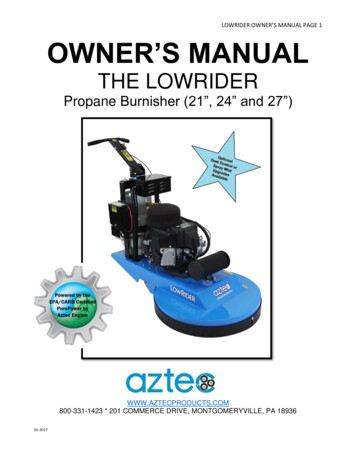
OWNER'S MANUALMODEL P474-0140Wire ConnectionsTOTALINE72Heat Off CoolFanOn FanAutoIf the terminal designations on your oldthermostat do not match those on thenew thermostat, refer to the chart belowor the wiring diagrams that follow.Wire from theold thermostatterminal markedFunctionCCommonW1, W or HAuxiliary HeatY1 or YOCoolingRev. ValveInstall on thenew thermostatconnector markedC (optional)W2YO(Energize to Cool)BBRev. Valve(Energize to Heat)G or FFanGRc, R, M, Vr, APowerRThermal Insulating SheetA label is provided on the backplatethat prevents drafts originating insidethe wall from entering the thermostat.These drafts, left unchecked, maycause incorrect room temperaturereadings.Please do not remove this labelfrom the thermostat. Insert the wiresthrough the slots provided in the labelas shown in Fig. 1Wire SlotsPage 12CW2YBOGR4Z95MODEL: P474-014097061606USE SIZE “AA”ALKALINE BATTERIESMADE IN CHINAFig. 1
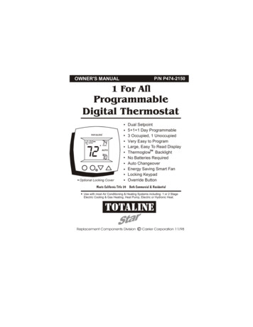
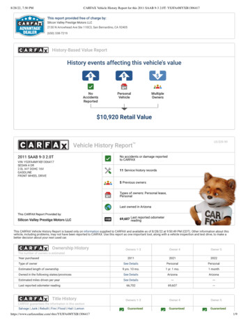
OWNER'S MANUALMODEL P474-0140Sample Wiring Diagrams5 Wire, 1 Stage Cooling, 2 Stage Heat, Heat Pump with O reversing valve.Residential Heat Pumps, split systems & package units, with auxiliary heat.Common wire optional*CW2YBOGRFANGREVERSING VALVEOCOMPRESSORW2 YPOWERR5 Conductor 18 to 22 gaugeunshielded cable from thethermostat to the equipment.ELECTRIC HEAT* Common wire is optional in all installations.If a common wire is not used thethermostat must be powered by two AA alkaline batteries. These batteriesmust be replaced (page 10) each year or when the Low Battery indicator is displayed(page 3).Page 13
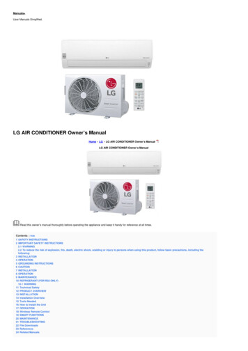
OWNER'S MANUALMODEL P474-0140Sample Wiring Diagrams4 Wire, 1 Stage Cooling, 1 Stage Heat, Heat Pump with O reversing valve.Residential Heat Pumps, split systems & package units, with no auxiliary heat.Common wire optional*CW2YBOGRFANGREVERSING VALVEOCOMPRESSORYPOWERR4 Conductor 18 to 22 gaugeunshielded cable from thethermostat to the equipment.* Common wire is optional in all installations.If a common wire is not used thethermostat must be powered by two AA alkaline batteries. These batteriesmust be replaced (page 10) each year or when the Low Battery indicator is displayed(page 3).Page 14
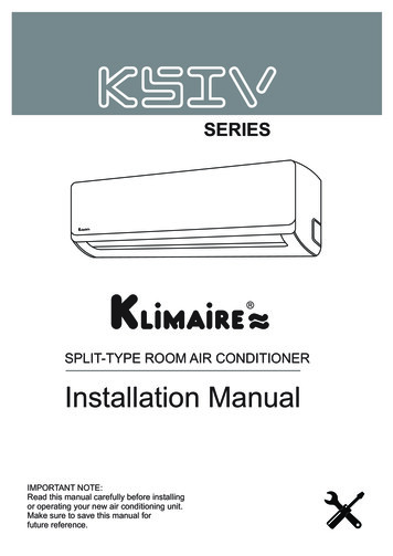
OWNER'S MANUALMODEL P474-0140Sample Wiring Diagrams4 Wire, 1 Stage Cooling, 1 Stage Heat, Heat Pump with B reversing valve.Residential Heat Pumps, split systems & package units, with no auxiliary heat.Common wire optional*CW2YBOGRFANGREVERSING VALVEBCOMPRESSORYPOWERR4 Conductor 18 to 22 gaugeunshielded cable from thethermostat to the equipment.* Common wire is optional in all installations.If a common wire is not used thethermostat must be powered by two AA alkaline batteries. These batteriesmust be replaced (page 10) each year or when the Low Battery indicator is displayed(page 3).Page 15
OWNER'S MANUALMODEL P474-0140Sample Wiring Diagrams5 Wire, 1 Stage Cooling, 2 Stage Heat, Heat Pump with B reversing valve.Residential Heat Pumps, split systems & package units, with auxiliary heat.Common wire optional*CW2YBOGRFANGREVERSING VALVEBCOMPRESSORW2 YPOWERR5 Conductor 18 to 22 gaugeunshielded cable from thethermostat to the equipment.ELECTRIC HEAT* Common wire is optional in all installations.If a common wire is not used thethermostat must be powered by two AA alkaline batteries. These batteriesmust be replaced (page 10) each year or when the Low Battery indicator is displayed(page 3).Page 16
OWNER'S MANUALMODEL P474-0140Test OperationTurn on the power to the Heat Pump.TOTALINE72Fan On FanAutoHeat Off CoolTOTALINE72Fan On FanAutoHeat Off CoolOn the thermostat, slide the Mode Switchto HEAT. Press the UP or DOWN buttonuntil the set temperature is 10 degrees aboveroom temperature. The HVAC unit shouldenergize in the heating mode. Note: Youmay need to wait up to five minutes forheating to energize due to the compressorlockout feature. There is a two minute minimum run-time for first stage heating.On the thermostat, slide the Aux HeatSwitch to the NORMAL position. If thethermostat is system powered the Aux Heatindicator will illuminate indicating that thethermostat has energized Aux Heat (page 7).TOTALINE72Heat Off CoolFan On FanAutoTWO STAGE OPERATION - The 2nd stageof heat (auxiliary heat) is turned on whenthe room temperature is equal to or lessthan: the setpoint minus the 1st stagedeadband (one degree, non-adjustable),minus the 2nd stage deadband (twodegrees, non-adjustable).CoolingHeating2nd Stageturn onDeadbandDeadbandDeadbanddb 2(non-adj. 2 )db 1(non-adj. 1 )db 1(non-adj. 1 )1st Stageturn onPage 17Heat or CoolSetpoint1st Stageturn on
OWNER'S MANUALMODEL P474-0140Test OperationTOTALINE72Fan On FanAutoHeat Off CoolOn the thermostat, slide the Mode Switchto COOL. Press the UP or DOWN buttonuntil the set temperature is 10 degrees belowroom temperature. The HVAC unit shouldenergize in the cooling mode (Page 6).Note: You may need to wait up to five minutesfor cooling to energize due to the compressorlockout feature.TOTALINE72Heat Off CoolFan On FanAutoOn the thermostat, slide the Mode Switch toOFF, then slide the Fan Switch to Fan On.The fan should turn on and run continuously(Page 6).Page 18
OWNER'S MANUALMODEL P474-0140TroubleShootingTOTALINE72Fan On FanAutoHeat Off CoolTOTALINE72Fan On FanAutoHeat Off CoolTOTALINE72Heat Off CoolFan On FanAutoSYMPTOM: The slide switches on the thermostatare very difficult to move.CAUSE: The backplate of the thermostat isscrewed too tightly into a wall that is notperfectly flat.REMEDY: Loosen the screws holding thethermostat into the wall.SYMPTOM: The Air Conditioning does notattempt to turn on.CAUSE: The cooling setpoint is set toohigh, the Mode Switch is not set forCool, the batteries are too weak, or theAux. Heat Switch is set for Emergency.REMEDY: Consult the Normal Operationsection in this manual to:Lower the cooling setpoint (Page 6)Correct the Mode Switch position (Page 6)Replace the batteries (Page 10)Adjust the Aux Switch to Normal (page 7)SYMPTOM: The fan does not turn on even thoughthe compressor has energized.CAUSE: The Fan Switch is not completely in theOn or Auto position.REMEDY: Slide the Fan Switch firmly into the Onor Auto position.Page 19
OWNER'S MANUALMODEL P474-0140TroubleShootingTOTALINE72FanOn FanAutoHeat Off CoolTOTALINE72Heat Off CoolFanOn FanAutoSYMPTOM: Aux Heat does not turn on.CAUSE: The Aux Heat Switch is set forLockout.REMEDY: Consult the Aux Heat sectionof this manual to slide the AuxHeat Switch to Normal (Page 7).SYMPTOM: The Heating does not attemptto turn on.CAUSE: The heating setpoint is set toohigh, the Mode Switch is not set forHeat, the batteries are too weak, or theAux Heat Switch is set for Emergency.REMEDY: Consult the Normal Operationsection in this manual to:Raise the heating setpoint (Page 6)Correct the Mode Switch position(Page 6)Replace the batteries (Page 11)Adjust the Aux Switch to Normal (Page 7)Battery StatP/N P474-0140cFCTested to Complywith FCC StandardsFOR HOME OR OFFICE USE4Z95P/N 88-419Rev. 2Page 20
OWNER'S MANUALMODEL P474-0140WarrantyFive-Year Warranty - This Product is warranted to be free from defects in material andworkmanship. If it appears within five year from the date of original installation, whether or notactual use begins on that date, that the product does not meet this warranty, a new orremanufactured part, at the manufacturer’s sole option to replace any defective part, will beprovided without charge for the part itself provided the defective part is returned to the distributorthrough a qualified servicing dealer.THIS WARRANTY DOES NOT INCLUDE LABOR OR OTHER COSTS incurred for diagnosing, repairing,removing, installing, shipping, servicing or handling of either defective parts or replacementparts. Such costs may be covered by a separate warranty provided by the installer.THIS WARRANTY APPLIES ONLY TO PRODUCTS IN THEIR ORIGINAL INSTALLATION LOCATION ANDBECOMES VOID UPON REINSTALLATION.LIMITATIONS OF WARRANTIES – ALL IMPLIED WARRANTIES (INCLUDING IMPLIED WARRANTIES OFFITNESS FOR A PARTICULAR PURPOSE AND MERCHANTABILITY) ARE HEREBY LIMITED IN DURATION TOTHE PERIOD FOR WHICH THE LIMITED WARRANTY IS GIVEN. SOME STATES DO NOT ALLOW LIMITATIONSON HOW LONG AN IMPLIED WARRANTY LASTS, SO THE ABOVE MAY NOT APPLY TO YOU. THEEXPRESSED WARRANTIES MADE IN THIS WARRANTY ARE EXCLUSIVE AND MAY NOT BE ALTERED,ENLARGED, OR CHANGED BY ANY DISTRIBUTOR, DEALER, OR OTHER PERSON WHATSOEVER. ALLWORK UNDER THE TERMS OF THIS WARRANTY SHALL BE PERFORMED DURING NORMAL WORKINGHOURS. ALL REPLACEMENT PARTS, WHETHER NEW OR REMANUFACTURED, ASSUME AS THEIRWARRANTY PERIOD ONLY THE REMAINING TIME PERIOD OF THIS WARRANTY.THE MANUFACTURER WILL NOT BE RESPONSIBLE FOR:1. Normal maintenance as outlined in the installation and servicing instructions or owner’smanual, including filter cleaning and/or replacement and lubrication.2. Damage or repairs required as a consequence of faulty installation, misapplication,abuse, improper servicing, unauthorized alteration or improper operation.3. Failure to start due to voltage conditions, blown fuses, open circuit breakers or otherdamages due to the inadequacy or interruption of electrical service.4. Damage as a result of floods, winds, fires, lightning, accidents, corrosive environments orother conditions beyond the control of the Manufacturer.5. Parts not supplied or designated by the Manufacturer, or damages resulting from their use.6. Manufacturer products installed outside the continental U.S.A., Alaska, Hawaii, andCanada.7. Electricity or fuel costs or increases in electricity or fuel costs for any reason whatsoeverincluding additional or unusual use of supplemental electric heat.8. ANY SPECIAL INDIRECT OR CONSEQUENTIAL PROPERTY OR COMMERCIAL DAMAGE OF ANYNATURE WHATSOEVER. Some states do not allow the exclusion of incidental orconsequential damages, so the above may not apply to you.This warranty gives you specific legal rights and you may also have other rights which mayvary from state to state.Page 21
the thermostat. Carefully unpack the thermostat. Save the screws and instructions. Turn off the power to the Heat Pump at the main fuse panel. Proper installation of the thermostat will be accomplished by following these step by step instructions. If you are unsure about any of these steps, call a qualified technician for assistance. Step #1 .