Transcription
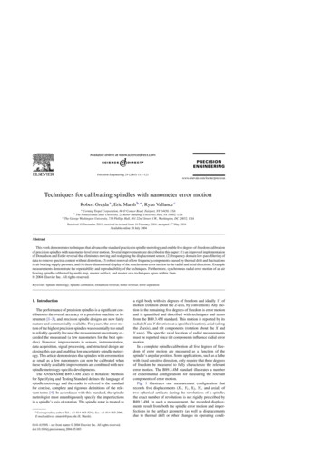
Precision Engineering 29 (2005) 113–123Techniques for calibrating spindles with nanometer error motionRobert Grejda a , Eric Marsh b, , Ryan Vallance caCorning Tropel Corporation, 60 O’Connor Road, Fairport, NY 14450, USAThe Pennsylvania State University, 21 Reber Building, University Park, PA 16802, USAThe George Washington University, 738 Phillips Hall, 801 22nd Street N.W., Washington, DC 20052, USAbcReceived 10 December 2001; received in revised form 16 February 2004; accepted 17 May 2004Available online 28 July 2004AbstractThis work demonstrates techniques that advance the standard practice in spindle metrology and enable five degree-of-freedom calibrationof precision spindles with nanometer-level error motion. Several improvements are described in this paper: (1) an improved implementationof Donaldson and Estler reversal that eliminates moving and realigning the displacement sensor, (2) frequency domain low-pass filtering ofdata to remove spectral content without distortion, (3) robust removal of low frequency components caused by thermal drift and fluctuationsin air bearing supply pressure, and (4) three-dimensional display of the synchronous error motion in the radial and axial directions. Examplemeasurements demonstrate the repeatability and reproducibility of the techniques. Furthermore, synchronous radial error motion of an airbearing spindle calibrated by multi-step, master artifact, and master axis techniques agree within 1 nm. 2004 Elsevier Inc. All rights reserved.Keywords: Spindle metrology; Spindle calibration; Donaldson reversal; Estler reversal; Error separation1. IntroductionThe performance of precision spindles is a significant contributor to the overall accuracy of a precision machine or instrument [1–3], and precision spindle designs are now fairlymature and commercially available. For years, the error motion of the highest precision spindles was essentially too smallto reliably quantify because the measurement uncertainty exceeded the measurand (a few nanometers for the best spindles). However, improvements in sensors, instrumentation,data acquisition, signal processing, and structural design areclosing this gap and enabling low uncertainty spindle metrology. This article demonstrates that spindles with error motionas small as a few nanometers can now be calibrated whenthese widely available improvements are combined with newspindle metrology-specific developments.The ANSI/ASME B89.3.4M Axes of Rotation: Methodsfor Specifying and Testing Standard defines the language ofspindle metrology and the reader is referred to the standardfor concise, complete and rigorous definitions of the relevant terms [4]. In accordance with this standard, the spindlemetrologist must unambiguously specify the imperfectionsin a spindle’s axis of rotation. The spindle rotor is treated as Correspondingauthor. Tel.: 1-814-865-5242; fax: 1-814-865-2986.E-mail address: emarsh@psu.edu (E. Marsh).0141-6359/ – see front matter 2004 Elsevier Inc. All rights reserved.doi:10.1016/j.precisioneng.2004.05.003a rigid body with six degrees of freedom and ideally 1 ofmotion (rotation about the Z-axis, by convention). Any motion in the remaining five degrees of freedom is error motionand is quantified and described with techniques and termsfrom the B89.3.4M standard. This motion is reported by itsradial (X and Y directions at a specified location), axial (alongthe Z-axis), and tilt components (rotation about the X andY axes). The specific axial location of radial measurementsmust be reported since tilt components influence radial errormotion.In a complete spindle calibration all five degrees of freedom of error motion are measured as a function of thespindle’s angular position. Some applications, such as a lathewith fixed sensitive direction, only require that three degreesof freedom be measured to fully characterize the relevanterror motion. The B89.3.4M standard illustrates a numberof experimental configurations for measuring the relevantcomponents of error motion.Fig. 1 illustrates one measurement configuration thatrecords five displacements (X1 , Y1 , X2 , Y2 , and axial) oftwo spherical artifacts during the revolutions of a spindle;the exact number of revolutions is not rigidly prescribed byB89.3.4M. In such a measurement, the recorded displacements result from both the spindle error motion and imperfections in the artifact geometry (as well as displacementsdue to thermal drift or other changes in operating condi-
114R. Grejda et al. / Precision Engineering 29 (2005) 113–123Fig. 1. Double ball artifact and capacitance probes for five degree-of-freedom measurements.tions). Several techniques can separate spindle error motionfrom artifact form errors, including Donaldson reversal,Estler reversal, multi-step, and multi-gage methods [5–9].A second measurement configuration, having compellingadvantages as described by Liebers et al. [10], replaces thespherical artifacts with a second, precision spindle called the“master axis”. The rotor of the master axis spindle rotateswith the rotor of the spindle under test, just as an artifactdoes in traditional measurements; however, the master axisstator is restrained from rotation about the Z-axis. The re-Fig. 2. Synchronous and asynchronous radial error motion of a ball bearing hard disk drive spindle over 128 revolutions.
R. Grejda et al. / Precision Engineering 29 (2005) 113–123straint, which must not constrain the five degrees of freedom of error motion, is effectively realized with a lappedsteel sphere in contact with a gage block mounted on thestator of the master axis spindle [11]. Displacement sensorstarget the non-rotating master axis stator and measure thecombined error motion of both spindles. Donaldson reversal or other error separation techniques are used to separatethe master axis error motion from that of the spindle undertest.Total error motion, which is the difference between runoutand artifact form error, is traditionally illustrated as a function of the spindle’s angular position using a polar plot. Themean contour of the total error motion is referred to as averageor synchronous error motion, which recently emerged as anequivalent but more descriptive term since average error motion is synchronized to the rotation. The difference betweenthe total error motion and the synchronous error motion isthen referred to as asynchronous error motion, since it is notsynchronized to the rotation. For example, Fig. 2 shows polar plots of the synchronous and asynchronous componentsof radial error motion from 128 revolutions of a ball bearingspindle from a hard disk drive. The synchronous error, givenas 20 nm in Fig. 2, is the difference between the maximumand minimum values on the synchronous error motion profile.2. BackgroundThe metrology of machine tools and their componentshas roots back to the early 1900s. Scheslinger was the firstto establish specific tests for qualifying the performance ofmachine tools and key components such as spindles [12].Scheslinger’s tests of a machine tool spindle used a mechanical displacement indicator on the rotor to measure the totalindicated reading (TIR), which is now recognized to be thesuperposition of the form error of the measured surface andthe spindle error motion.Tlusty and Bryan are considered the founders of modernspindle metrology for developing complete methods for accurately quantifying spindle performance and presenting theresults in the intuitive form of polar plots [1,13]. Donaldson’scontribution of a robust error separation (reversal) techniquein 1972 made possible spindle error motion measurementsof accuracy limited only by sensors, data acquisition, structural design and technique [5]. During this period, Bryan,Clouser and Holland’s 1967 paper was the basis for a newdocument published by the International Institution for Production Engineering Research (CIRP) in 1975 and again in1976 on unifying the terminology of axes of rotation [14,15].These papers became the basis of the B89.3.4M standardthat was eventually published in 1985. In the years that followed, a rich body of work has been published with eachsuccessive article further reducing the uncertainty in spindle metrology through clever developments of hardware andtechnique.115For example, digital processing of spindle measurementswas introduced by Vanherck and Peters in 1973, and becamewidespread in the 1980s as rotary encoders and resolvers appeared more frequently on precision machine tools [16]. Inpractice, spindle speed fluctuations necessitate accurate angular triggering to properly synchronize data from successiverevolutions. Researchers like Arora et al. used resolvers tomonitor the phase of artifact eccentricity and efficiently remove it [17]. Murthy et al. used digital notch filters tuned tothe spindle rotation rate as a method to remove artifact eccentricity [18].One of the most important advances in spindle metrologysince the work by Bryan and Tlusty was the refinement ofcapacitance sensors with high sensitivity and resolution. Anexcellent background on capacitive sensors is available fromFoldvari and Lion [19]. By the late 1980s, researchers developed nanometer-resolution sensors that could be appliedto the challenge of measuring precision spindle error motion[20]. Chapman designed and built a spindle analyzer capableof measuring radial, axial, and tilt error motion with a resolution of 5 nm [21]. Hansen introduced a general-purposeinstrument in 1988 using the now popular double sphere artifact for complete calibrations [22].Other developments have been thoughtfully researched,including alternatives to the Donaldson and Estler reversalmethods for separating spindle error motion from artifactform error. These alternatives include multi-position techniques where measurements are recorded with displacement sensors at multiple angular locations and multi-probemethods where measurements are recorded from multiplesensors simultaneously. Whitehouse pointed out that themulti-position and multi-probe methods are insensitive to(i.e., do not accurately detect) certain harmonics of the error motion depending on the number of gages, positioningof the gages, or steps used in acquiring the data [23]. Donaldson and Estler reversal are widely preferred since theycompletely separate all harmonics of error motion and artifact form. Regardless of the error separation scheme used ina particular spindle calibration, the literature and experienceshow that the accuracy of all methods is adversely affectedby imperfectly re-positioned gages or by using multiplegages of unequal sensitivity. Therefore great care is requiredwhen reorienting a displacement sensor and reversing thespindle or artifact.3. Experimental techniquesDespite continuous improvements in metrology, it remainsformidable to calibrate the highest precision spindles withnanometer error motion. In this section we describe our experimental techniques that are subsequently shown to repeatablyand reproducibly calibrate precision spindles with error motion at the nanometer level. These techniques are describedin the context of externally pressurized air bearing spindlescommonly found in diamond turning, precision grinding, and
116R. Grejda et al. / Precision Engineering 29 (2005) 113–123Fig. 3. Donaldson reversal using a rotary table to eliminate the need for relocating the displacement sensor.a variety of metrology applications. Other types of precisionspindles, including hydrostatic and rolling element, may becalibrated using the same techniques.3.1. Improved reversal implementationDonaldson and Estler reversal requires that two measurements be taken 180 apart relative to the spindle stator. Thisis conventionally achieved by simultaneous measurementsfrom two sensors or by moving one sensor between measurements. Either way, it is difficult to locate the sensor(s) exactly180 apart, at precisely the correct radial or axial locations,and at identical angles of incidence (90 ).A new implementation of Donaldson and Estler reversalwas developed and investigated by Grejda that allows reversal to be executed without moving the displacement sensor[24]. In this implementation, illustrated in Fig. 3, the spindleunder test is mounted on a rotary table, and a special chuck(referred to as a reversal chuck) is used between the spindleand artifact. The stator of the spindle under test is rotatedwith respect to the artifact and gage, rather than rotatingthe gage and artifact with respect to the spindle stator asdone in the conventional method. A high quality rotary tablecan rotate the spindle stator with accuracy better than 10arc-seconds, which makes this approach equally well suitedfor multi-position error separation. The reversal chuck, illustrated in Fig. 4, enables accurate 180 reversal of theartifact using a pin in jig-ground indexing holes and accurate centering with a spherical pilot that mates in a carbidesocket.This simple but powerful improvement allows the procedure of calculating the spindle error motion at a particularlocation to be made with a single displacement sensor that isnever moved. Rotating sensitive direction error motion mayalso be calculated by simply repeating the procedure with therotary table oriented at 90 and 270 .3.2. Sampling and signal processingThe spindle measurements are processed in three steps.First, the data are anti-alias filtered, sampled and stored inequal angular increments as triggered by a rotary encodermounted on the spindle’s rotor. Second, a best fit, low orderpolynomial is removed from the data to reduce the influenceof very low frequency disturbances such as thermal drift andair supply pressure fluctuations. Finally, the data are low-passfiltered in the Fourier domain to remove the fundamentalcomponent (when appropriate) and spectral content above theusable bandwidth of the instrument. The first and third stepsare discussed in this section and the removal of low frequencydisturbances is discussed separately in Section 3.3.To prevent aliasing, the output from any analog displacement sensor must, without exception, be filtered with an analog anti-alias filter prior to sampling by a data acquisitionFig. 4. The separated halves of the reversal chuck showing the precisionground mating surfaces and spherical pilot.
R. Grejda et al. / Precision Engineering 29 (2005) 113–123system. In spindle metrology, the appropriate anti-alias cutoff frequency fcutoff depends on the number of encoder countsper revolution c (typically a power of 2 such as 1024, 4096, oreven higher) and the angular speed n of the spindle as shownin Eq. (1). For our rotary encoder with 1024 counts per revolution, fcutoff must be lower than 8.5n Hz. In practice, thecutoff frequency is usually somewhat less to allow for therolloff characteristics of realizable analog filtersfcutoff (Hz) c[counts per revolution] n (rpm).2 60(1)An additional constraint on the usable bandwidth of an instrument is structural resonance. Spectral content above approximately one-third the first resonant frequency fr is excessively amplified by resonance and should be removed. Thefirst structural resonance of our instrument is 150 Hz in thesensing direction, which places a 50 Hz limit on bandwidth.The maximum allowable spindle speed during calibrationnmax depends upon fr and the desired cutoff S as shown inEq. (2). We use S 50 cpr (cycles per revolution) in our measurements, so the maximum spindle speed is 60 rpmnmax (rpm) 60fr (Hz).3S (cpr)(2)Once the data are properly anti-alias filtered and sampled,any additional low-pass filtering and removal of the fundamental component is carried out in the Fourier domain. Thereare two principal advantages to Fourier domain signal processing in spindle metrology. First, Fourier domain filteringcauses no distortion on the data and precisely removes onlythe desired spectral components from the signal. Second, thesynchronous and asynchronous components of spindle errormotion are intuitively discernible in the Fourier domain. Thesynchronous component appears in the integer cpr Fourierbins, and the asynchronous component appears in the remaining, non-integer, Fourier bins. The non-integer bins of theasynchronous component are of special interest when measuring rolling element spindles because of the predictablefrequencies at which defects appear.Therefore, the measurements are low-pass filtered in theFourier domain to remove spectral content above the desiredcutoff frequency S. It is also convenient to remove the fundamental (1 cpr) error motion in the Fourier domain for radialand face measurements. In both cases, the appropriate Fourierbins are set to zero on both sides of the Nyquist frequency.The fundamental error motion is removed by zeroing out thebin corresponding to the one cpr component and the corresponding bin on the mirror image of the Nyquist frequency.Similarly, the low-pass filter for limiting spectral content toS is implemented by zeroing out the Fourier bins above S andup to the mirror image of S on the other side of the Nyquistfrequency. The metrologist can quickly check the effect ofrunning the data through low-pass filters with cutoffs suchas 5, 10, and 50 cpr, just as is done with traditional roundness measuring instruments. Thompson describes the utilityof this approach in more detail [25].117It is important to note that the Fourier domain representation of the data is considered in units of cpr rather than Hzsince the data are synchronized to angle, not time. The rangeof cpr bins in the Fourier domain equals the number of encoder counts in a single revolution c. The resolution equalsthe inverse of the number of revolutions over which data arerecorded. For example, if 32 revolutions of data are recorded,then the resolution is 1/32 of a cpr. High resolution is helpfulin resolving the closely spaced spectral content seen in ballbearing spindles.After post-processing in the Fourier domain, an inversediscrete Fourier transform returns data to the angular domain,where error motion values are computed and the data are visualized using polar plots or the advanced techniques shownlater in this paper.3.3. Thermal and air supply pressure fluctuationsAlthough it is possible to minimize the sensitivity of astructure to variation in temperature through clever designand materials selection, some drift is still possible over shorttime intervals at the nanometer-level [26,27]. In the measurements performed for this article, the test duration was about30 s, and thermally induced drift varied from 0 to 5 nm. Additional displacement fluctuations occurred due to variationsin the regulated air pressure supplied to the air bearing spindles. Fig. 5 shows the low-frequency drift in the structuralloop of the test hardware. The regular cycling of the HVACsystem every 4.3 min is apparent, as is additional very lowfrequency drift due to other environmental effects.Low frequency signals, like thermal drift and pressure fluctuations, which have periods exceeding the recording time ofthe spindle measurements, should be filtered from the measurements prior to a discrete Fourier transform. These lowfrequency signals do not necessarily have equal values atthe beginning and end of the recorded data. This causes awell-known signal-processing phenomenon called leakageand is an artifact of the discrete Fourier transform since itassumes that the signal repeats indefinitely and that the testperiod captures an integer number of cycles. In other applications, leakage may be minimized through thoughtfuluse of windowing functions, but this introduces additionalwell-documented problems and should not be used for spindle metrology.A more appropriate solution for removing low frequencydrift and minimizing leakage in spindle calibration is to fitand remove a low order polynomial from each data set. Innumerous tests with 30 s data captures it was found that asecond-order polynomial fit the thermal drift data with itsmuch longer period of oscillation.3.4. Description of hardwareAll results described in Section 4 were measured duringthe calibration of unmotorized air bearing spindles (Professional Instruments 4R) rotating at about 60 rpm with a nom-
118R. Grejda et al. / Precision Engineering 29 (2005) 113–123Fig. 5. Temperature variation and radial displacement drift over a six-hour interval.inal air pressure of 830 kPa. A 1024 count encoder (Heidenhain ERO incremental) generated a pulse train for triggeringand a once per revolution index pulse. The spindle under testis placed on a rotary table (Moore LRT) that is mounted on athree-axis measuring machine (Moore No. 3 Universal Measuring Machine). The three axes of travel allow convenientplacement of the displacement sensor at the correct locationand the rotary table eliminates the need to move the sensorbetween tests as described in Section 3.1. The spherical pilotmaintains the centering of the artifact or master axis duringreversal. The reversal chuck also features jig ground locatingholes at 0 , 90 , 180 , and 270 for accurate angular rotationin either fixed or rotating sensitive direction measurements.Displacements are measured by capacitive sensors with2 mV/nm sensitivity (Lion Precision DMT drivers with C1-Cprobes) with an internally adjustable analog filter set to acutoff of 100 Hz for this testing. The analog output from thesensors is sampled by a 16-bit data acquisition card (NationalInstruments PCI-6110E). The data are subsequently analyzedusing custom-designed software that executes the thermaldrift removal, Fourier domain post processing and displaysthe results on an intuitive user interface [28]. The analysis ofthe data follows procedures described in Sections 3.2 and 3.3as well as in the B89.3.4M standard.4. Experimental resultsIn this section, four experiments demonstrate the abilityto calibrate spindles with nanometer error motion. First, therepeatability of the techniques and apparatus are demonstrated. Second, the fixed sensitive direction synchronousradial error motion of two spindles is measured using themaster axis method with sub-nanometer repeatability. Third,reproducibility of measurements using the different methods of Donaldson, multi-step and multi-probe error separation is demonstrated. Fourth, the results of a complete, fivedegree-of-freedom spindle calibration are shown using newFig. 6. Repeatability of 10 consecutive master axis measurements, without reversal.
R. Grejda et al. / Precision Engineering 29 (2005) 113–123119Fig. 7. Synchronous radial error motion of (a) master axis spindle directly on stator center and (b) spindle under test 177 mm above stator center.plotting techniques that enable quick interpolation of radialerror motion at any axial location and face error motion atany radial location.4.1. Measurement repeatability without reversalThe repeatability of the techniques and apparatus, excluding the reversal procedure, is first assessed with 10 independent master axis measurements over the course of 4 days.Since reversal was not performed, the results include the combined synchronous radial error motion of the spindle undertest and the master axis. The bold line in Fig. 6 indicates amean of 7.52 nm. The dashed lines above and below the meanindicate 2 standard deviations, and the standard deviationfor these tests is 0.08 nm. We therefore conclude that 95% ofthe measurements would fall within about 0.16 nm of themean assuming a normal distribution.4.2. Measurement repeatability with reversalIn a second experiment, the fixed sensitive direction synchronous radial error motion measurement by the master axismethod was conducted four times, including error separationby Donaldson reversal. All four sets of measurement resultsfor the spindle under test and master axis are shown in thepolar plots of Fig. 7 and summarized in Table 1. The resultsdemonstrate that the repeatability is less than 0.2 nm whenDonaldson reversal is included in the measurement procedure. This suggests that the new, rotary table implementation of Donaldson reversal does not significantly degrade themeasurement repeatability.To confirm the master axis results shown in Fig. 7, wecompared the synchronous radial error motion as measuredby the master axis method to results obtained using a sphericalartifact having an out-of-roundness of 35 nm. It is importantto note that radial error motion results can only be compared ifmeasured at the same axial location with respect to the spindleunder test (now 254 mm above the center of the spindle undertest). Both techniques yield the synchronous error motionvalue to within 1 nm. Fig. 8 shows the close agreement usingpolar plots, and Table 2 summarizes the comparison.Table 1Results of four synchronous radial error motion measurementsTestRadial error motionSpindle under test (nm)Master axis spindle (nm)12345.25.45.45.22.42.42.52.4Fixed sensitive direction; radial error motion; 50 cpr cutoff; 32 revolutionsof data; 60 rpm; axial position 177 mm above bottom stator center; masteraxis method; includes reversal.
120R. Grejda et al. / Precision Engineering 29 (2005) 113–123Fig. 8. Comparison of synchronous radial error motion of a spindle undertest measured with a lapped spherical artifact and with a master axis.4.3. Measurement reproducibility by comparison ofmulti-step, multi-probe, and Donaldson reversalAn additional advantage of mounting the spindle undertest on a rotary table is that multi-probe and multi-step error separation techniques can also be performed withoutmoving the displacement sensor. Therefore, we demonstrate reproducible measurements of synchronous radialerror motion by comparing the results of alternative measurement methods. The fixed sensitive direction radial errormotion and the form error of the lapped spherical artifactare compared using results obtained by Donaldson reversal,a 16-position multi-step test, and a 3-probe error separationtest. The apparatus was completely disassembled between thetests.As before, the tests were carried out on an unmotorizedProfessional Instruments air bearing spindle with 830 kPa airpressure at 60 rpm for 32 revolutions. The radial error moTable 2Comparison of radial error motion of a spindle under test using a master axisand a lapped artifactTest methodMaster axisLapped artifactRadial error motionSynchronous (nm)Asynchronous (nm)8.37.74.35.5Fixed sensitive direction; radial error motion; 50 cpr cutoff; 32 revolutionsof data; 60 rpm; axial position 254 mm above stator center; Donaldsonreversal.tion of the spindle is measured at an axial position 177 mmfrom the geometric center of the stator using a lappedspherical artifact as the capacitive displacement sensor’starget. The Donaldson reversal was performed as describedearlier.The multi-step technique was performed using a step sizeof 22.5 for a total of 16 measurements with an additionalre-measurement of the 0 position to check the repeatability with the first measurement. With the spindle on the rotary table, the multi-step procedure is readily carried outand requires only a bit of post-processing to perform thewell-known calculations [23]. The form error of the artifactis determined from averaging the 16 measurements, and canbe subtracted from the original measurement to compute thespindle error motion. Because of the 16 steps used in thismeasurement, the multi-step error separation method onlydistorts the Fourier components that are integer multiples of16 cpr (16, 32, 48 cpr, etc).The multi-probe method was carried out using the rotarytable with only minor modifications to the approach documented in the literature [24]. For this study, the computationswere performed using data collected for probes at 0 , 122.5 ,and the 202.5 position (asymmetrically) to avoid maskingthe third harmonic of the error motion.Fig. 9 shows the form error of the lapped spherical artifact as calculated by the three different methods. The formerror results match closely with the exception of a deviationat approximately 160 . The agreement in form error is otherwise excellent, differing by less than 1 nm. Additionally, thesphere’s form error values measured by the three techniquesagree to better than 1 nm.The fixed sensitive direction synchronous radial error motion of the spindle is also shown in Fig. 9. The Donaldsonand multi-step results agree within a nanometer for the entirepolar plot. However, the multi-probe results differ by 1.5 nmin some locations. This discrepancy may be attributed to themulti-probe method, which imperfectly computes the content of all frequency bins of the error motion during separation, rather than just specific harmonics as in the case ofmulti-step testing (integer multiples of 16 for the multi-stepmethod used here).Since the results agree within 1.5 nm for all three errorseparation methods, we conclude that the techniques and apparatus can reproducibly calibrate spindles at the nanometerlevel.4.4. Five degree-of-freedom characterizationTo this point, only fixed sensitive direction radial error motion at specific axial positions has been discussed. However,the accuracy of an object made by turning, facing, and general contouring is affected by radial, axial and tilt error motion of the axis of rotation used to generate it. The B89.3.4Mstandard outlines the procedure for making multiple measurements to determine the error motion at any axial or radialposition.
R. Grejda et al. / Precision Engineering 29 (2005) 113–123121Fig. 9. Polar plots of artifact form error and synchronous radial error obtained by three error separation techniques. (a) Artifact form error, (b) synchronousradial error of spindle.We performed five degree-of-freedom spindle calibrationsusing both the master axis method and the lapped doubleball method with excellent agreement. The results shown inFigs. 10 and 11 use the master axis method with Donaldsonreversal to compute radial and face error motion of the masteraxis and te
116 R. Grejda et al./Precision Engineering 29 (2005) 113-123 Fig. 3. Donaldson reversal using a rotary table to eliminate the need for relocating the displacement sensor. a variety of metrology applications. Other types of precision spindles, including hydrostatic and rolling element, may be calibrated using the same techniques. 3.1.