Transcription
An Evaluation of Optical Flow using Lucas and Kanade’sAlgorithmCarman NeustaedterUniversity of CalgaryDepartment of Computer ScienceCalgary, AB, T2N 1N4 Canada 1 403 210-9507carman@cpsc.ucalgary.cabecause a co-worker could interrupt at an inappropriatetime.ABSTRACTVideo offers distance-separated co-workers with a richawareness of who is available for conversation orcollaboration. By broadcasting video, however, the privacyof individuals becomes threatened because others now seepotentially sensitive information. This risk is heightenedfor telecommuters who use video to connect to a remoteoffice from home. Blurring video is one technique that haspreviously been studied to help preserve privacy. Mostblurring techniques blur the entire video, however, it isdesirable to be able to blur regions of the video differentlyif multiple people are present. Optical flow can be used inthis situation to distinguish which regions contain differentpeople by their level of activity. This paper evaluates animplementation of Lucas and Kanade’s algorithm forcomputing optical flow and discusses possible applicationsfor it in videoconferencing that is sensitive to privacyissues. The implementation is found to compute accurateoptical flow for small pixel displacements, yet real-timecomputation is only possible for small frame sizes.Telecommuters who work from home and connect to aremote office using video face increased privacy threats, ashomes are inherently private in nature. Video links placetelecommuters in two different environments where there isa disparity between levels of appropriateness. For example,working without a shirt on may be quite appropriate forthose working at home, but the same level of undress is notappropriate for an office environment. Video attempts toplace the telecommuter under the appropriatenessconstraints of both locations. To further complicate thesituation, others present in the home, such as familymembers who gain no benefit from the video link still incurthe privacy threat.Blur filtration is one technique that has been studied tomask sensitive details in video that may be consideredthreatening to one’s privacy [5,17], such as a person’sactivity, a person’s appearance, or the location and itsappearance. Most filtration techniques are only capable ofmasking the entire video sequence an equal amount. Incases where multiple people are present within a homethere exists a desire to be able to blur regions of the videodifferently for each person. Some people, such as thetelecommuter working, may be appropriate to broadcast atfull fidelity while someone walking into the room invarying levels of undress may not be. The person workingcould be blurred less than the person walking into theroom. For such situations, being able to distinguishbetween a high level of activity and a low level of activitywould be desirable. Areas of high activity, such as asecondary person walking into a room could be blurredmore than a region containing someone working.Keywords. Optical flow, Lucas and Kanade, videoconferencing, motion, privacy.INTRODUCTIONEveryday communication and interaction between coworkers is held together by an awareness of those who arearound and available [2,5,9]. Awareness helps peopledecide if and when to smoothly move into and out ofconversation or collaboration. This awareness is easily andnaturally gained by those located in close physicalproximity [7,16]. People can see if another is busy bysimply glancing in their office or cubicle. As peoplebecome spread over distance, however, this awarenessbecomes difficult to gain unless technology is present[7,10].Optical flow algorithms show potential in this areabecause they are able to compute motion between frames ofvideo. The optical flow that is computed for each pixel in aframe could be used to determine which regions of thevideo frame contain large amounts of flow or motion.These regions could then be treated accordingly for theirsuspected level of privacy threat. Many optical flowalgorithms are quite computationally expensive, however,and not suitable for use while transmitting video to others.Lucas and Kanade [13] present a differentiation method forcomputing optical flow that has shown computationalVideo is capable of providing rich awareness overdistance and has been suggested by many researchers as atechnology capable of mediating communication [2,48,11,14,15,17]. As video broadcasts information aboutone’s awareness, such as a user’s current activity and levelof availability, it may be presenting information at anundesirable level and threatening the user’s privacyhowever. The user’s privacy could be violated just aseasily though if no awareness information is presented-1-Neustaedter, 2002
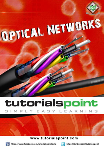
potential in various implementations by other researchers[1,12].This paper discusses an implementation of the Lucasand Kanade algorithm for computing optical flow and itsapplication to privacy preservation techniques formediating privacy when video is used in homes. Theimplementation is evaluated based on its accuracy incomputing flow and distinguishing levels of high activityfrom levels of low activity. The computation performanceof the implementation is also analyzed for various framesizes.Figure 2: A video frame (left) compared to its smoothedversion (right).Lim and Gamal [12] use a modified version of Lucasand Kanade’s algorithm that utilizes advancements inCMOS image sensor technology to compute more accurateoptical flow measurements using high frame rates. Theirtechnique first computes an optical flow estimate betweentwo frames at high frame rates using the Lucas and Kanademethod. Next, the optical flow is computed from thesuccessive images at standard frame rates. This new valueis combined with the initial estimate to create a final flowvalue. Lim and Gamal conclude that by using high framerate sequences they are able to handle pixel displacementsof up to 10 pixels/frame at 30 frames/sec, which is muchhigher than the reported 1-2 pixels/frame displacementcapabilities of the original Lucas and Kanade algorithm.RELATED WORKThe algorithm presented by Lucas and Kanade [13] is animage registration technique that can be used to computeoptical flow. Image registration techniques attempt to findan optimal value for a disparity vector, h, which representsan object’s displacement between successive images.Methods to find the disparity vector prior to Lucas andKanade relied on computationally expensive or nonoptimal techniques.One such method performs anexhaustive search for h that examines all possible valuesfor the disparity vector [13]. An alternative strategy isfound in hill-climbing techniques that evaluate differencefunctions at all points in a region, choosing the point thatminimizes the difference [13]. Hill-climbing techniquescan lead to false peaks that produce local, rather thanglobal, optimums for h however. A third technique,sequential similarity detection, computes an error value foreach possible disparity vector and then applies a methodsimilar to alpha-beta pruning in min-max trees, wheredisparity vectors with large error values are eliminated[13].IMPLEMENTATIONThe Lucas and Kanade algorithm as described by Barron etal. [1] follows four main steps to compute optical flow foreach frame in a video sequence. Frames are first smoothedwith a spatiotemporal filter to reduce errors in gradientestimation (Figure 2). Next, gradients are estimated in x, y,and t (time) for each pixel in the current frame. Gradientsare then smoothed and placed in a linear system (Figure 1).Finally, the linear system is solved for the two velocitycomponents, u and v.This section describes theimplementation used and discusses areas where deviationsfrom other implementations were made.Lucas and Kanade’s algorithm [13] presents an imageregistration method that examines fewer possible values ofh than previous algorithms to improve computationperformance. An initial estimate of h is made and theniteratively updated based on the average spatial intensitygradient found at each point within a fixed sized window.The contribution of each gradient to the value of h isweighted based on an estimate of the gradient’s error.Iteration ceases after a specified length of time or when hconverges. Smoothing an image is shown to help improveconvergence, but can cause greater errors if an object issuppressed entirely [13]. It is assumed in the algorithm thatpixels from the image are moving at a constant velocity andcorresponding pixels in the images fall within a fixed sizedwindow. An implemented version of Lucas and Kanade’salgorithm is described in Barron, Fleet, and temporal Smoothing. Each frame must be smoothedto reduce errors that may be produced duringdifferentiation. Smoothing first occurs spatially where a 1dfilter is used to convolve the image first in x and then y,similar to standard image smoothing techniques. Tosmooth temporally, Barron et al. [1] suggest using aGaussian filter with standard deviation of 1.5 pixelsframes. This requires the storage of a large set of framesfor smoothing and delays the algorithm’s flow output,which is undesired if the implementation is to be used inbroadcasting video over the Internet. To alleviate thisproblem, my implementation uses a simple two-frameweighted average. The current pixel’s value is averagedwith the pixel from the same location in the previous frame,where α gives more weight to the value of the currentE(t n) (1- ) E(n-1) 0.75E(n)Figure 3: The formula for temporally smoothing the value,E, of a pixel.Figure 1: The linear equation used for computing theoptical flow components, u and v-2-Neustaedter, 2002
frame’s pixel (Figure 3). A sample frame and its smoothedframe are shown in Figure 2.delayed by two frames, but for video conferencing thiswould be seemingly unnoticeable at standard video framerates. As well, for the first two frames and the last twoframes in a frame sequence optical flow is not computablebecause a five-frame window is not available. Next, Ix, Iy,and It are used to calculate Ix2, Iy2, IxIy,, IxIt,, and IyIt,.Estimating the Gradients. Each frame is convolved in x, y,and t with a 1 x 5 kernel to compute Ix, Iy, and It, for eachpixel. The kernel used in the implementation is shown infigures 4 and 5 along with calculations of Ix and Iy using asample set of image values. The same kernel is used byBarron et. al [1]. Gradients in x and y can be computedwithin the current frame, however It must be computedusing a set of five frames – the current frame, two previousframes, and two subsequent frames – as shown in figure 6.The five-frame window needed for It causes output to 5510100-8Gradient Smoothing. Gradients are now smoothed for eachpixel in the frame within a 5 x 5 window using a 5 x 5kernel. The kernel used, as suggested by Barron et. al [1],is shown in figure 7 along with a sample smoothingcalculation for Ix2. The kernel gives greater weight togradients near the center of the 5 x 5 window.1010101010101Ix (2,2) ( -1 * 10 8 * 10 0 * 5 -8 * 5 1 * 5 ) / 12Figure 4: A sample gradient calculation for 05551010-82Figure 7: A sample gradient smoothing for Ix.Solving the Linear System. A linear system is constructed,as shown in figure 1, to contain all gradient information.Next, the 2 x 2 matrix containing gradient information for xand y (Figure 1) can be solved by first creating thequadratic equation shown in steps 1-3 of figure 8. Thisequation can then be solved for its two eigenvalues, 1 andusing the quadratic formula shown in figure 9. Once the2,eigenvalues are found, they are compared to a threshold, 1, and will fall into one of three cases:1010101010101Case 1: 1and 2 A is invertible and the system can be solved forthe two velocity components, u and v usingelementary linear algebra.Iy (2,2) ( -1 * 10 8 * 5 0 * 5 -8 * 5 1 * 10 ) / 12Figure 5: A sample gradient calculation for Iy.Case 2: Case 3: and12 A is singular and therefore non-invertible; thegradient flow is then normalized to give u and v.1 and2 No optical flow can be computed; u and v are zero.EVALUATION OF FLOW ACCURACYThe algorithm’s implementation is evaluated based on itsaccuracy in computing optical flow. This evaluationlooked at two main aspects: is the computed optical flowequivalent to the actual displacement of pixels betweenvideo frames and does the accuracy of the computed flowdiffer as pixel displacements increase between frames.It (2,2) ( -1 * 5 8 * 5 0 * 5 -8 * 5 1 * 10 ) / 12Figure 6: A sample gradient calculation for It.-3-Neustaedter, 2002
A a11a12wIx2wIxIya21a22wIxIywIy21. det (A – I) 02. (a11 – )(a22 – ) – (a12)2 03.2a) Square moving down.b) Walking left to right.c) Moving head left and right.d) Moving head and walking.– (a11 a22) a11a22 – a122Figure 8: The steps taken to create a quadratic equationfor the 2 x 2 matrix A. -b b2 – 4acFigure 10: Four input videos (not shown at actual size).2aframes in length, and play at a rate of 15 fps. Pixeldisplacements within each scene are unknown, andunfortunately each of these videos suffers from the captureeffects of the Winnov camera.a 1b - (a11 a22)MethodFirst, a series of four square test patterns was used to testthe accuracy of the optical flow in each major direction:left, right, up, and down. Optical flow for each frame isstored in a file and also used as input for an output videosequence that visually displays the optical flow. The outputvideo sequence is of the same frame size, but contains twoframes less than the original video because for the last twoframes a five-frame window does not exist and thealgorithm is unable to compute flow. In the output video,red is used to indicate flow in x where a value of 255indicates a magnitude of flow greater than or equal to 3,170 indicates a magnitude of flow equal to 2, 70 indicates amagnitude of flow equal to 1, and 0 indicates no flow. Theoutput video uses blue to show flow in y and uses the samevalue system as red. Each pixel’s green component is set tozero. The flow stored in the output file is compared to theactual pixel displacements, and the output frame sequenceis used to visually detect problems in computation.c a11a22 – a122Figure 9: The quadratic formula used to find twoeigenvalues for the 2x2 matrix.MaterialsA set of 26 accuracy-test video sequences was created totest the accuracy of the algorithm. The test set contains aseries of four videos, 176 x 144 pixels in size (QCIFvideoconferencing size), containing a square of 40 x 40pixels, which is composed of random colours. Each ofthese four videos shows the square moving at a rate of 1pixel/frame either left, right, up, or down on a backgroundcomposed also of random colours. These videos are 50frames in length and play at a rate of 10 fps. Figure 10shows the video of the square moving down; videos of thesquare moving left, right, or up are very similar. Theaccuracy-test set also includes 19 video sequencescontaining the same square moving left, except at speedsranging from 2 pixels/frame to 20 pixels/frame.Next, 19 square test patterns were used to test theaccuracy of flow at pixel displacements ranging from 2pixels/frame to 20 pixels/frame. Optical flow for eachframe is also stored in a file and the same output videosequences are created. Again, the flow stored in the outputfile is compared to the actual pixel displacements, and theoutput frame sequence is used to visually detect problemsin computation.Three of the accuracy-test video sequences werecaptured using a Winnov Videum PC Camera (Figure 10).The first contains an actor walking across the room fromleft to right. The second video contains an actor sitting infront of a computer working and moving his head left andright. The final video shows the same actor working whilemoving his head left and right, and now contains a secondactor walking behind him across the scene from left toright. All three videos are 176 x 144 pixels in size, 75Finally, 3 test patterns containing human actors areused to further analyze the accuracy of the output. Opticalflow for each frame is again stored in a file and the same-4-Neustaedter, 2002
output video sequences are created. This output video isused to visually analyze the accuracy of the flow, but flowvalues found in the file are not analyzed because the actualpixel displacements in the video are unknown.ResultsThe algorithm is able to compute optical flow for all fourvideo sequences containing the square moving at 1pixel/frame with a large degree of accuracy. Flow for themoving pixels is computed within a 2-pixel range, i.e. forpixels moving at a rate of 1 pixel/frame, the algorithmeither computed 1, 2, or 3 for the pixel’s flow.Anexception occurs for regions along the edge of the squarewhere the algorithm is much less accurate. The outputvideos, shown in figure 11, display flow in x with red andflow in y with blue. Visually it is apparent that the flow isquite accurate and the algorithm is able to detect the correctsize and shape of the moving object, as well as differentiatebetween flow in x and y.a) Motion: Downb) Motion: Upc) Motion: Leftd) Motion: Righta) Speed: 1 pixel/frameb) Speed: 2 pixels/framec) Speed: 4 pixels/framed) Speed: 6 pixels/framee) Speed: 8 pixels/framef) Speed: 10 pixels/frameg) Speed: 15 pixels/frameh) Speed: 20 pixels/frameFigure 11: Four output videos of optical flow for a movingsquare (not shown at actual size).Figure 12: Eight output videos of optical flow for a movingsquare (not shown at actual size).The 19 test sequences that compare pixeldisplacements per frame show less accuracy in threerespects. First, when pixel speeds are greater than 1pixel/frame, the algorithm begins to fail in correctlydifferentiating flow between x and y. For the squaremoving left, flow artifacts begin to appear in y and thistrend increases as speed increases. Figure 12 visuallyconfirms this trend in optical flow output. An analysis ofprogram execution shows that the majority of regionscontaining y artifacts also contain large eigenvalues and uand v are computed using the least squares methodpresented in the first eigenvalue case. Secondly, whenpixel speeds are greater than 3 pixels/frame, the algorithmbegins to fail in correctly identifying the shape of themoving object; flow artifacts begin to appear behind themoving square where no flow should be present. Again,program execution shows that these regions also containlarge eigenvalues and use the least squares method.Finally, when pixel speeds are greater than 4 pixels/framethe accuracy of the flow’s magnitude begins to deteriorateand the algorithm computes the flow within a 4-pixel range,i.e. for pixels moving at a rate of 1 pixel/frame, thealgorithm computes a flow magnitude between 1 and 5.The final three test sequences contain unknown pixeldisplacements and the output flow values cannot becompared directly. Figure 13 shows the output flow videofor each of the these test sequences. Visual analysis of thefirst video containing the actor walking shows that themajority of the movement is in x, which is correct. It alsoshows motion in y as the person walks, which accounts forslight movements in y during each stride. The secondoutput video of the actor working while moving his head,-5-Neustaedter, 2002
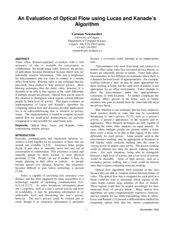
3.176 x 144 (QCIF)4.320 x 2405.352 x 288 (CIF)6.640 x 4807.720 x 480 (DV)MethodEach of the 7 test videos is used as input to the optical flowalgorithm. The total computation time for each frame sizeis recorded along with the corresponding frame per secondprocessing rate. Each test video is processed for opticalflow on a Dell workstation with a 1.4 GHz Intel Xeonprocessor and 512 MB of RAM running Windows XP asthe operating system. Several background applicationswere running during testing, similar to typical scenarioswhen videoconferencing software is used.a) Walking left to right.ResultsProcessing rates range from 20 fps for 100 x 100 sizeframes to 0.5 fps for 720 x 480 size frames. Processingrates for all frame sizes are shown in figure 14. Idealvideoconferencing frame sizes of CIF and 320 x 240 werecomputed at a rate of 1.8 fps and 2.5 fps, respectively.During computation, the processor utilization was 100% forall frame sizes, as compared to 10-30% utilization prior tocomputation.b) Moving head left and right.DISCUSSIONc) Moving head and walking.Figure 13: Three output videos of optical flow for movingactors, each shown at 2 points in time (not shown at actualsize).visually confirms that motion is almost solely in x and it isalso apparent that these motions are very subtle as indicatedby the light shades of red. The third video shows that thealgorithm is capable of differentiating two different rates ofmotion: the faster motion of the walking person and thesubtle head movements of the working person.The optical flow implementation presented is capableof differentiating regions of different activity level. Forexample, figure 13c shows that the background motion ofthe person walking is much larger than the motion of theperson who is working. Closer analysis of the computedflow shows that as the speed of objects increase, theaccuracy of the algorithm deteriorates by first failing tocompletely distinguish flow in x from flow in y and then byfailing to identifying the correct shape and size of themoving object. The algorithm was tested with speeds of upto 20 pixels/frame, yet it is unlikely that video containingpeople will have movement of this magnitude, especially ifthe intended use is capturing work activity. The algorithmfails to compute high displacement rates correctly becausepixels begin to move outside the 5 x 5 window that is usedto compute and smooth gradient estimations. If it weredesirable to handle high displacements, a larger windowsize could be evaluated. For privacy applications, the flowproduced is accurate enough.EVALUATION OF COMPUTATION PERFORMANCEThe algorithm’s implementation is also evaluated based onits computational performance in computing optical flow.This evaluation compared the number of framescomputable per second for varying frame sizes andmonitored the processor’s utilization.MaterialsA set of 7 computation-test video sequences was created totest the computation rate of the algorithm. Each video inthe set contains a 40 x 40 square composed of randomcolours. The square moves at a rate of 1 pixel/frame over abackground composed of random colours. Videos are 50frames in length and play at a rate of 10 fps. The framesizes selected for testing are:1.100 x 1002.160 x 120In order to apply optical flow to videoconferencing systemsthat address privacy concerns, the optical flow algorithmmust meet two main criteria. First, it should be accurateenough to distinguish regions of differing activity levels,for example, distinguishing regions containing someoneworking from regions containing someone walking into aroom in the background. Second, it must be able tocompute optical flow in real-time so that frames can beprocessed prior to being broadcast to others.The implementation is also seen to tax theworkstation’s processor quite heavily, yet it is clear that the-6-Neustaedter, 2002
Figure 14: The processing rate of each frame size tested.computational power of processors and other hardwareperipherals will only increase in the future, thus easilyremedying this problem. When using videoconferencingover the Internet, users are normally capable of obtainingframe rates between 5 and 10 fps, depending greatly on theInternet connection used and network congestion. Asexpected, when frame size increases so does thecomputation time and the corresponding frame per secondflow output suffers as a result. The computation of QCIFframes and smaller frame sizes either fell within the idealvideoconferencing frame rates or exceeded its performancerequirements. It is desirable, however, to use a frame sizeof 320 x 240 for videoconferencing, which is larger thanQCIF frames. This size fell outside the desired rate, but itis expected that implementation optimization couldimprove its performance to a desirable level. Possiblealterations may include optimizing calculations for specificprocessor technology and using less numerical precisionduring computation.form of privacy preservation, yet this idea still requires itsown evaluation.FUTURE WORKThe current implementation is capable of extracting framesfrom an AVI file and producing a second AVI that visuallyrepresents the optical flow computed. Future versionsshould be capable of using frames directly from an attachedPC camera, especially if optical flow is to be applied as atool for videoconferencing.The current implementation shows that optical flow iscapable of differentiating regions of a video containingvarying levels of activity. Future implementations shoulduse the calculated optical flow as input to a privacypreservation technique such as blur filtration, where regionsof high activity could be blurred more than regions of lowactivity. Such a design could also be evaluated for itscomputational performance, as well as its effectiveness inpreserving the privacy of multiple individuals.CONCLUSIONAlthough the flow output has not been used explicitlyin any privacy preservation techniques, video frames thatvisually display flow present an interesting situation(Figures 11, 12, and 13). Flow frames naturally mask boththe background details of a scene and the person’sappearance in a scene. As well, a person’s activitybecomes partially masked – it is possible to understand thegeneral activity of the person, but specific details areunknown (Figure 13). Flow output appears to offer its ownVideo is used by distance-separated workers, whetherworking from home or an office, for providing awarenessinformation to others. This awareness is used to decide ifand when to move into conversation or collaboration.When using video, however, information that may beconsidered threatening to one’s privacy is broadcast toothers. Optical flow presents a method for detectingvarying degrees of activity in video, which could be used inconjunction with privacy preservation techniques. Such-7-Neustaedter, 2002
communication, Proc. of CHI ’92 Human Factors inComputing Systems, New York: ACM Press, pp. 37-48.7. Greenberg, Saul. (1996), Peepholes: Low CostAwareness of One's Community, ACM SIGCHI'96Conference on Human Factors in Computing System,Companion Proceedings, pp. 206-207.8. Greenberg, S. and Kuzuoka, H. (2000). Using Digitalbut Physical Surrogates to Mediate Awareness,Communication and Privacy in Media Spaces. PersonalTechnologies, 4(1), January.9. Hudson, S.E., and Smith, I. (1996), Techniques forAddressing Fundamental Privacy and DisruptionTradeoffs in Awareness Support Systems, inProceedings of the Conference on Computer SupportedCooperative Work (CSCW’96), Cambridge, MA.10. Kraut, R., Egido, C., and Galegher, J. (1988), Patternsof contact and communication in scientific observation.Proc ACM CSCW ’88, pp. 1-12.11. Lee, A., Girgensohn, A., Schlueter, K. (1997) NYNEXPortholes: Initial User Reactions and RedesignImplications, Group ’97, ACM Press, pp. 385-394.12. Lim, S., Gamal, A., (2001) Optical Flow Estimationusing High Frame Rate Sequences, Proceedings of the2001 International Conference on Image Processing,v.2, p.925-928.13. Lucas, B., and Kanade, T. (1981) An Iterative ImageRegistration Technique with an Application to StereoVision, Proc. of 7th International Joint Conference onArtificial Intelligence (IJCAI), pp. 674-679.14. Mantei, M., Baecker, R., Sellen, A., Buxton, W.,Milligan, T., and Wellman, B. (1991) Experiences in theuse of a media space. Proc. of CHI ’91 Human Factorsin Computing Systems, New York: ACM Press, pp. 203209.15. Tang, J.C., Isaacs, E., and Rua, M. (1994). SupportingDistributed Groups with a Montage of LightweightInteractions.Proc. of the ACM Conference onComputer-Supported Cooperative Work, CSCW ’94,ACM Press, pp. 23-34.16. Whittaker, S., and O’Conaill, B. (1997), The Role ofVision in Face-to-Face and Mediated Communication,in Video Mediated Communication, Finn, Sellen, andWilbur eds., LEA Press.17. Zhao, Q.A., and Stasko, J.T. (1998), Evaluating ImageFiltering Based Techniques in Media SpaceApplications, in Proceedings of the Conference onComputer Supported Cooperative Work (CSCW’98),Seattle, pp. 11-18.techniques attempt to mask sensitive details in video wheremultiple people may be present. To be used with privacysensitive videoconferencing systems, optical flow must becomputable in a real-time and present a reasonable level ofaccuracy.This paper presented an implementation of Lucas andKanade’s [13] differentiation method for computing opticalflow in video. The implementation has been shown tocompute flow in real-time for small image sizes andpresents a desirable level of flow accuracy, capable ofdistinguishing regions varying in activity level. Thealgorithm does consume a large amount of systemresources, however it is predicted that continuingtechnological improvements in computer hardware willresolve this problem. The implementation has yet to beused in conjunction with privacy preservation techniques,although it presents its own technique where videosvisualizing the flow output naturally mask details of aperson’s appearance and the appearance of the capturedlocation.Acknowledgements. Thanks to Michael Boyle for hisinvaluable help and for the use of his collaborativemultimedia toolkit.REFERENCES1. Barron, J.L., Fleet, D.J., Beauchemin. (1994),Performance of Optical Flow Techniques. Proc. ofInternational Joint Conference of Computer Vision,Vol. 12, No. 1, pp. 43-772. Bellotti, V. (1996), What you don’t know can hurt you:Privacy in Collaborative Computing. Proc. HCI ’96,Springer, pp. 241-261.3. Bellotti, V., and Sellen, A. (1993), Design for Privacy inUbiquitous Computing Environments, in Procee
CMOS image sensor technology to compute more accurate optical flow measurements using high frame rates. Their technique first computes an optical flow estimate between two frames at high frame rates using the Lucas and Kanade method. Next, the optical flow is computed from the successive images at standard frame rates. This new value